Herunterladen Inhalt Inhalt Diese Seite drucken
PR electronics 9116 Bedienungsanleitung

PR electronics 9116 Bedienungsanleitung

Universalmessumformer
Vorschau ausblenden Andere Handbücher für 9116:
Inhaltsverzeichnis

Werbung

Verfügbare Sprachen

Verfügbare Sprachen

9 1 1 6
U n i v e r s a l -
M e s s u m f o r m e r
N r . 9 1 1 6 V 1 0 4 - D E
P r o d u k t v e r s i o n : 9 1 1 6 - 0 0 3

Werbung

Kapitel

Inhaltsverzeichnis
loading

Inhaltszusammenfassung für PR electronics 9116

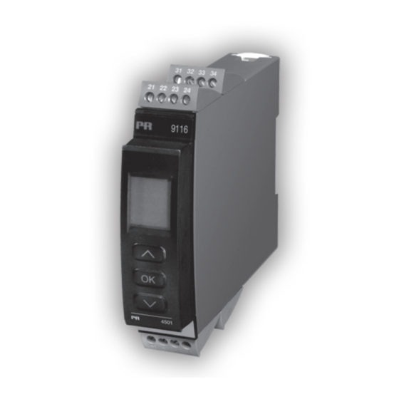
  • Seite 1 9 1 1 6 U n i v e r s a l - M e s s u m f o r m e r N r . 9 1 1 6 V 1 0 4 - D E P r o d u k t v e r s i o n : 9 1 1 6 - 0 0 3...
  • Seite 2 PR electronics A/S tilbyder et bredt program af analoge og digitale signalbehandlingsmoduler til industriel automation. Programmet består af Isolatorer, Displays, Ex-barrierer, Temperaturtransmittere, Universaltransmittere mfl. Vi har modulerne, du kan stole på i selv barske miljøer med elektrisk støj, vibrationer og temperaturudsving, og alle produkter opfylder de strengeste internationale standarder.
  • Seite 3: Inhaltsverzeichnis

    Grafische Abbildung der Relaisfunktion „Fenster“ ....29 Grafische Abbildung der Relaisfunktion „Schaltpunkt“ ... 30 Appendix ....................31 IECEx Installation Drawing .............. 32 ATEX Installation Drawing ............... 36 FM Installation Drawing ..............40 INMETRO Installation Drawing ............44 Safety Manual ..................48 9116 - Product Version 9116-003...
  • Seite 4: Warnung 2

    Installation, Montage und Demontage von Leitungen. Fehlersuche im Gerät. Reparaturen des gerätes und austausch von sicherungen dür- fen nur von PR electronics a/s vorgenommen werden. WaRnUng Die Frontplatte des Gerätes darf nicht geöffnet werden, weil hier- durch die Kontakte zur Kontaktierung des Frontdisplays 4501 beschädigt werden können.
  • Seite 5: Empfang Und Auspacken

    Sollten Zweifel bezüglich der richtigen Handhabung des Gerätes bestehen, sollte man mit dem Händler vor Ort Kontakt aufnehmen. Sie können aber auch direkt mit PR electronics gmbh, www.prelectronics.dk Kontakt aufnehmen. Der Einsatz von verdrillter Leitung ist nicht erlaubt außer die Enden sind mit Aderendhülsen versehen.
  • Seite 6: Kalibrierung Und Justierung

    Wasser leicht angefeuchtet ist. haFtUng In dem Umfang, in welchem die Anweisungen dieses Handbuches nicht genau eingehalten werden, kann der Kunde PR electronics gegenüber keine Ansprüche geltend machen, welche ansonsten entsprechend der eingegangenen Verkaufsvereinbarungen existieren können. zERlEgUng DEs systEMs 9000 abbildung 1: Das Gerät wird von der Power Rail...
  • Seite 7: Erweiterte Merkmale

    Anforderungen der Richtlinie IEC 61508. technische Merkmale • 1 grüne und 1 rote Leuchtdioden in der Front zeigen den normalen Betrieb und Fehlfunktionen an. 1 gelbe Leuctdiode zeigt den Relaisstatus an. • 2,6 kVAC galvanische Trennung zwischen Eingang, Ausgang und Versorgung. 9116 - Product Version 9116-003...
  • Seite 8: Anwendungen

    Versorgung +19,2...31,2 VDC Gerätestatus N.C. Gerätestatus Versorgung über zone 0, 1, 2, Power Rail 20, 21, 22, M1 / cl. i/ii/iii, Div. 1 gr. a-g zone 2 / cl. 1, Div. 2, gr. a-D oder sicherer Bereich 9116 - Product Version 9116-003...
  • Seite 9: Pr 4501 Display / Programmierfront

    Kommunikations- und Relaisstatus und den Status der SIL-Konfiguration (offen / verriegelt) an. Statischer Punkt = SIL-verriegelt, blinkender Punkt = nicht SIL- verriegelt. • Der Zugriff auf die Programmierung kann mit der Eingabe eines Passwortes blockiert werden. Das Passwort wird im Messumformer gespeichert, um den höchsten Grad an Schutz gegen nicht autorisierte Änderungen der Konfiguration sicherzustellen. Montage / installation • Stecke das 4501 auf die Front des 9116. 9116 - Product Version 9116-003...
  • Seite 10: Bestellangaben 9116B

    / V-Eingang, programmierbar ... 0,4...60 s Kalibrierungstemperatur ........20...28°C Genauigkeit: Der höhere Wert der allgemeinen Werte oder Grundwerte: allgemeine Werte Eingangs- Absolute Temperatur- Genauigkeit koeffizient ≤ ±0,1% d. Messsp. ≤ ±0,01% d. Messsp. / °C Alle 9116 - Product Version 9116-003...
  • Seite 11 Relative Luftfeuchtigkeit ........ < 95% RF (nicht kond.) Abmessungen, ohne Frontdisplay (HxBxT) ..109 x 23,5 x 104 mm Abmessungen, mit Frontdisplay (HxBxT) ..109 x 23,5 x 116 mm Schutzart ..............IP20 Gewicht ................ 185 g / 200 g mit 4501 9116 - Product Version 9116-003...
  • Seite 12 Vergleichsstellenkompensation (CJC): über externen Sensor in der Anschlussklemme 5910Ex ......20...28°C ≤ ± 1°C -20...20°C und 28...70°C ≤ ± 2°C über internen Sensor ........±(2,0°C + 0,4°C * ∆t) ∆t = interne Temperatur - Umgebungstemperatur 9116 - Product Version 9116-003...
  • Seite 13 Signalbereich ............. 4...20 mA Belastungsstabilität ..........≤ 0,01% d. Messspanne / 100 W Belastungswiderstand ........... ≤ (V -3,5) / 0,023 A [W] Versorgung Externe 2-Draht-Versorgungsbereich ..... 3,5...26 VDC Wirkung der externen 2-Draht Versorgungsspannungsänderung ..... < 0,005% d. Messspanne / V 9116 - Product Version 9116-003...
  • Seite 14: Konfiguration Der Sensorfehlerüberprüfung

    Cert No............PREl 070902 P0002 C03.01 SIL 2-zertifiziert über Full Assessment gemäß IEC 61508 FMEDA-Bericht - www.prelectronics.de d. Messspanne = der momentan gewählten Messspanne Konfiguration der sensorfehlerüberprüfung Sensorfehlerüberprüfung: Gerät: Konfiguration Fühlerfehlererkennung ERR.ACT=NONE - OUT.ERR=NONE. 9116 Sonst: 9116 - Product Version 9116-003...
  • Seite 15: Eingangssignal Außerhalb Des Bereichs

    Fühler gebrochen oder Alle SE.BR Leiter-Widerstand zu hoch LIN.R Für Lin. R_0%≥ ca. 18 W SE.SH Fühler-Kurzschluss Fühler gebrochen oder Alle SE.BR Leiter-Widerstand zu hoch TEMP Pt100 bis Pt1000 und Ni50 bis Ni1000 SE.SH Fühler-Kurzschluss 9116 - Product Version 9116-003...
  • Seite 16: Fehleranzeige

    CPU FLASH-Fehler* Hardware Fehler MR.ER CPU RAM-Fehler* Hardware Fehler MS.ER CPU Spannungsversorgungs-Fehler* Hardware Fehler MP.ER CPU ProgFlow-Fehler** Hauptinitalisierung Hardware Fehler MI.ER Selbsttest fehlerhaft Hardware Fehler DE.ER Geräte-Fehler* Ungültiger Code Checksumme im Hardware Fehler FC.ER 4501 9116 - Product Version 9116-003...
  • Seite 17 Wenn der Fehler ein Sensorfehler ist, blinkt das Hintergrundbeleuchtung auch - dies kann besätigt (eingestellt) werden bei Drück von 3. Fehler wird durch Wegnahme der Versorgungsspannung zurück gesetzt! ** Fehler greift nur bei TE-Eingang. *** Fehler wird durch Durchschalten der Grundeinstellungen zurück gesetzt. 9116 - Product Version 9116-003...
  • Seite 18: Anschlüsse

    Strom Spannung 51 52 53 54 51 52 53 54 51 52 53 54 ausgänge Strom 2-Draht-Umformer Relais (Aktiver Ausgang) (Passiver Ausgang) 11 12 13 14 11 12 13 14 11 12 13 14 N.O. 9116 - Product Version 9116-003...
  • Seite 19: Blockdiagramm

    Blockdiagramm 9116 - Product Version 9116-003...
  • Seite 20: Signalfehler- Und Kabelfehler Erkennung Ohne Frontdisplay

    Ausgangs-Relais angesteuert Blinkt Angesteuert Offen Ausgangs-Relais angesteuert Geschlossen Blinkt Blinkt Abgefallen durch Kabel Kurzschluss / Bruch (if enabled) Ausgangs-Relais abgefallen Geschlossen Blinkt Blinkt Abgefallen durch Kabel Kurzschluss / Bruch (if enabled) Ausgangs-Relais abgefallen Blinkt Angesteuert Offen 9116 - Product Version 9116-003...
  • Seite 21: Konfiguration / Bedienung Der Funktionstasten

    Dokumentation für das Flussdiagramm. grundsätzliches Bei der Konfiguration des 9116 werden Sie durch alle Parameter geleitet und Sie können die Einstellungen wählen, welche zur Applikation passt. Für jedes Menü existiert ein scrollender Hilfetext welcher automatisch in der 3. Zeile im Display gezeigt wird.
  • Seite 22: Signal Und Sensorfehleranzeige Ohne Programmierfront

    Power: Das Relais ist so lange aktiv, wie die Versorgungsspannung anliegt. oFF: Das Relais ist deaktiviert. signalanstieg/-abfall: Das Relais kann bei ansteigenden oder abfallenden Eingangssignal aktiviert werden. verzögerung: Ein AN- sowohl als auch ein AUS-Verzögerungssignal kann im Bereich von 0...3600 s programmiert werden. 9116 - Product Version 9116-003...
  • Seite 23: Hauptfunktionen

    100%) angelegt und der aktuelle Wert wird über das 4501 eingegeben. Wenn Sie die Kalibrierung akzeptieren, wird das Gerät mit den neuen Werten übernommen. Wenn Sie später diese Werte verwerfen oder andere Parameter eingeben, wird die Werkskalibrierung übernommen. 9116 - Product Version 9116-003...
  • Seite 24 Power Rail: Im Menü ”Rail” können Sie wählen, ob Sensor-Fehler an die zentrale Überwachung im Power Control Unit PR 9410 weitergegeben werden sollen. safety integrity level (sil): Für Details sehen Sie bitte im Sicherheitshandbuch (Safety Manual) nach. 9116 - Product Version 9116-003...
  • Seite 25 Txt 6 Txt 6 TC.B TC.E TC.J TC.K Fortsetzung auf Seite 26 TC.L TC.N TC.R TC.S Flussdiagramm ADV.SET TC.T TC.U TC.W3 CONN TC.W5 TC.Lr TC.K ADV.SET SENSOR TC.TYPE Txt 2 Txt 10 Txt 18 Txt 31 9116 - Product Version 9116-003...
  • Seite 26: Wählbare Einheiten

    1.5 = Nur wenn die Konfiguration 1.1 = Nur wenn durch Passwort nicht durch Passwort gesichert. gesichert ist. Wählbare EINHEITEN: mm/s m3/min m/min m3/h in/s l/min UNIT Txt 9 ft/s gal/min in/min gal/h mils ft/min in/h mbar ft/h m/s2 [blank] 9116 - Product Version 9116-003...
  • Seite 27 Txt 19 REL.FUN Txt 19 20-4 20-0 23mA 4-20 850.0 0/3.5mA 0-20 -200 -199.0 NONE 4-20 23mA 150.0 O.RANGE OUT.ERR OUT.LO OUT.HI RESP. Txt 37 Txt 38 Txt 41 Txt 42 Txt 39 Zum Normal-Zustand 1.0 9116 - Product Version 9116-003...
  • Seite 28: Flussdiagramm, Erweiterte Einstellungen (Adv.set)

    OPEN 9999 LOCK Bestätigung der SIL-Konfiguration 2008 LOCK SETUP EN.SIL NEW.PAS CONFIG SIL.OK Txt 43 Txt 64 Txt 55 Txt 66 ....9116 - Product Version 9116-003...
  • Seite 29: Scrollender Hilfstext Im Display Zeile 3

    Eingabe Neuen Passworts Wähle FENSTER Funktion - Relais steuert 2 Schaltpunkte [56] Ermögliche Schnelleinstellungs-Funktionalität Wähle SCHALTPUNKT Funktion - Relais steuert 1 [57] Relais Schaltpunkt - Drücke 3 zum Speichern Schaltpunkt [58] Relais Schaltpunkt - Nur lesen 9116 - Product Version 9116-003...
  • Seite 30 Versorgung kurz unterbrechen FLASH Memory Fehler - Konfiguration kontrollieren [88] Ungültige Konfiguration oder Version [89] Hardware-Fehler [90] CJC Sensor-Fehler - Geräte-Temperatur kontrollieren [91] CJC Fehler - CJC Stecker Terminal kontrollieren [92] Keine Kommunikation [93] 9116 - Product Version 9116-003...
  • Seite 31: Grafische Abbildung Der Relaisfunktion „Fenster

    Relaisfunktion „Fenster“ 9116 - Product Version 9116-003...
  • Seite 32: Grafische Abbildung Der Relaisfunktion „Schaltpunkt

    Relaisfunktion „schaltpunkt“ Eingangs- Einschaltverzögerung signal Ausschaltverzögerung Schaltpunkt (steigend) Hysterese Zeit Relais eingeschaltet Geschlossen Relaiskontakt (N.O.) Offen 9116 - Product Version 9116-003...
  • Seite 33: Appendix

    FM installation drawing inMEtRo installation drawing safety manual 9116 - Product Version 9116-003...
  • Seite 34 For Installation in Zone 2 the following must be observed. The 4501 programming module is to be used solely with PR electronics modules. It is important that the module is undamaged and has not been altered or modified in any way. Only 4501 modules free of dust and moisture shall be installed.
  • Seite 35 For installation on Power Rail in Zone 2, only Power Rail type 9400 supplied by Power Control Unit type 9410 (Type Examination Certificate KEMA 07ATEX0152 X) is allowed. Revision date: Version Revision Prepared by: Page: 2012-07-04 V6 R0 9116 - Product Version 9116-003...
  • Seite 36 Term. 54-52; 51-52 21.4 V 0.16 μF 4 mH 54 μH/Ω 93 mA 1.13 μF 16 mH 218 μH/Ω 650 mW 4.15 μF 32 mH 436 μH/Ω Revision date: Version Revision Prepared by: Page: 2012-07-04 V6 R0 9116 - Product Version 9116-003...
  • Seite 37 Lo/Ro Term. 52-51, 51-52 16.6 V 0.4 μF 100 mH 25mH/Ω 0.2 mA 2.3 μF 100 mH 100mH/Ω 0.8 mW 9.5 μF 100 mH 200mH/Ω Revision date: Version Revision Prepared by: Page: 2012-07-04 V6 R0 9116 - Product Version 9116-003...
  • Seite 38: Atex Installationszeichnung

    4501 Für die Installation in Zone 2 ist Folgendes zu beachten: Das aufsteckbare Frontdisplay 4501 zur Programmierung ist ausschließlich mit PR electronics- Geräten zu verwenden. Es ist wichtig, dass das Display unbeschädigt ist, nicht umgebaut oder in irgendeiner Weise verändert wurde. Das 4501 darf nur frei von Staub und Feuchtigkeit installiert werden.
  • Seite 39 Für die Installation auf Power Rail in Zone 2 ist nur Power Rail Typ 9400 – in Verbindung mit dem Power Control Unit Typ 9410 (Type Examination Certificate KEMA 07ATEX0152 X) - erlaubt). Revision date: Version Revision Prepared by: Page: 2012-07-04 V6 R0 – DE01 9116 - Product Version 9116-003...
  • Seite 40 21.4 V 0.16 μF 4 mH 54 μH/Ω 93 mA 1.13 μF 16 mH 218 μH/Ω 650 mW 4.15 μF 32 mH 436 μH/Ω Revision date: Version Revision Prepared by: Page: 2012-07-04 V6 R0 – DE01 9116 - Product Version 9116-003...
  • Seite 41 Term. 52-51, 51-52 16.6 V 0.4 μF 100 mH 25mH/Ω 0.2 mA 2.3 μF 100 mH 100mH/Ω 0.8 mW 9.5 μF 100 mH 200mH/Ω Revision date: Version Revision Prepared by: Page: 2012-07-04 V6 R0 – DE01 9116 - Product Version 9116-003...
  • Seite 42: Fm Installation Drawing

    For Installation in Zone 2 / Division 2 the following must be observed. The 4501 programming module is to be used solely with PR electronics modules. It is important that the module is undamaged and has not been altered or modified in any way. Only 4501 modules free of dust and moisture shall be installed.
  • Seite 43 Warning: Do not mount or remove modules from the Power Rail when an explosive gas mixture is present. Revision date: Version Revision Prepared by: Page: 2012-06-08 V6 R0 9116 - Product Version 9116-003...
  • Seite 44 IIC or A,B Io, Isc 93 mA 1.13 μF 16 mH 218 μH/Ω IIB or C,E,F 650 mW 4.15 μF 32 mH 436 μH/Ω IIA or D,G Revision date: Version Revision Prepared by: Page: 2012-06-08 V6 R0 9116 - Product Version 9116-003...
  • Seite 45 IIC or A,B Io, Isc 0.2 mA 2.3 μF 100 mH 100mH/Ω IIB or C,E,F 0.8 mW 9.5 μF 100 mH 200mH/Ω IIA or D,G Revision date: Version Revision Prepared by: Page: 2012-06-08 V6 R0 9116 - Product Version 9116-003...
  • Seite 46 Corrente máx.:: 2 A AC / 2 ADC (terminais 11,12,13,14) 9116 RTD / LinR (terminais 31,32,33,34) (terminais 91,92,93,94,95) : 253 V; máx. 400 Hz TRILHO DE ENERGIA Revision date: Version Revision Prepared by: Page: 2013-05-31 V6 R0 9116 - Product Version 9116-003...
  • Seite 47 Para a instalação de trilho de energia na Zona 2, apenas o trilho de alimentação Rail 9400 fornecido pela Unidade de Controle de Potência 9410 é permitido. Revision date: Version Revision Prepared by: Page: 2013-05-31 V6 R0 9116 - Product Version 9116-003...
  • Seite 48 Term. 54-52; 51-52 21.4 V 0.16 μF 4 mH 54 μH/Ω 93 mA 1.13 μF 16 mH 218 μH/Ω 650 mW 4.15 μF 32 mH 436 μH/Ω Revision date: Version Revision Prepared by: Page: 2013-05-31 V6 R0 9116 - Product Version 9116-003...
  • Seite 49 Lo/Ro Term. 52-51, 51-52 16.6 V 0.4 μF 100 mH 25mH/Ω 0.2 mA 2.3 μF 100 mH 100mH/Ω 0.8 mW 9.5 μF 100 mH 200mH/Ω Revision date: Version Revision Prepared by: Page: 2013-05-31 V6 R0 9116 - Product Version 9116-003...
  • Seite 50: Safety Manual

    Safety manual unIVeRSal COnVeRteR 9116 this safety manual is valid for the following product versions: 9116-003 9116-002 9116-001 Version No. V3R0...
  • Seite 51 9116 Universal converter safety Manual 0 COntentS 1 Observed standards ..................... 2 Acronyms and abbreviations ..................3 Purpose of the product ....................4 Assumptions and restrictions for use of the product ..........4.1 Basic safety specifications .................. 4.2 Safety accuracy ....................
  • Seite 52 Safety Manual 9116 UniverSal converter 15 Fault reaction and restart condition ................16 User interface ....................... 16.2 Routing diagram ....................16.3 Routing diagram - Advanced settings (ADV.SET)..........17 Connections diagram ....................Version No. V3R0...
  • Seite 53: Observed Standards

    Error events, including cable faults, are monitored and signalled via the individual status relay and/or a collective electronic signal via the power rail. The 9116 has been designed, developed and certified for use in SIL 2 applications according to the requirements of IEC 61508.
  • Seite 54: Assumptions And Restrictions For Use Of The Product

    Safety Manual 9116 UniverSal converter assumptions and restrictions for use of the product Basic safety specifications Operational temperature range....-20...+60°C Storage temperature range...... -20...+85°C Power supply type, min......Double or reinforced Supply voltage ......... 19.2...31.2 VDC Relay output pulse length, min....70 ms Loop supply ..........
  • Seite 55: Sensor Errors

    Refer to section 14 - Safe parameterisation - user responsibility. 4.3.4 analogue output The connected safety PLC shall be able to detect and handle the fault indications on the analogue output of the 9116 converter by having a NAMUR NE43-compliant current input. 4.3.5 Relay output The relay output shall only be connected to equiment which has a current limiting function of 2 A.
  • Seite 56: Functional Specification Of The Non-Safety Functions

    Safety Manual 9116 UniverSal converter For RTD and linear resistance input sensors, cable resistances of up to 50 W per wire can be compensated if 3- or 4-wire connection is configured. For thermocouple sensors, cold junction temperature errors can be compensated, either by an internally mounted temperature sensor, or by an accessory connector with a built-in temperature sensor.
  • Seite 57: Hardware And Software Configuration

    Relay lifetime (Note 2 ) 100 000 times Note 1 : The 9116 contains no lifetime limiting components, therefore the PFH figures are valid for up to 12 years, according to IEC 61508. Note 2 : The user must calculate the product lifetime with regard to the relay lifetime.
  • Seite 58: Failure Category

    Safety Manual 9116 UniverSal converter failure category failure rates (1/h) for RTD, TC, LinR and Potentiometer input, Current output Fail Safe Detected 0.000E-0 Fail Safe Undetected 2.78E-07 Fail Dangerous Detected 3.52E-07 Fail Dangerous Undetected 4.30E-08 failure rates (1/h) for RTD, TC, LinR and Potentiometer input, Relay output Fail Safe Detected 0.000E-0...
  • Seite 59: Periodic Proof Test Procedure

    Any failures that are detected and that compromise functional safety should be reported to the sales department at PR electronics A/S. Repair of the device and replacement of circuit breakers must be done by PR electronics A/S only. 12 maintenance No maintenance required.
  • Seite 60: Sensor/Cable Fault Information Via Display Front 4501

    Safety Manual 9116 UniverSal converter 13.2.2 Sensor/cable fault information via display front 4501 When the function is enabled and supported by selected input type, sensor or cable faults are displayed as SE.BR (sensor break) or SE.SH (cable short-circuited). In case of sensor or cable fault the backlight flashes. This can be reset by pressing the 3 key.
  • Seite 61: Simulation (Sim)

    9116 Universal converter safety Manual 13.3.7 Simulation (SIm) It is possible to override the actual measured input signal by a simulated value. In the REL.SIM menu it is posible to simulate the relay state with out affecting the analogue output, by pressing .
  • Seite 62 Safety Manual 9116 UniverSal converter Pt.TYPE Pt sensor type (for SENSOR = Pt): 10 = Pt10 20 = Pt20 (No short circuit detection!) 50 = Pt50 100 = Pt100 200 = Pt200 250 = Pt250 300 = Pt300 400 = Pt400...
  • Seite 63 9116 Universal converter safety Manual CONNEC Selected sensor connection type for RTD or linear resistance measurements (for SENSOR = Ni or Pt or IN.TYPE = LIN.R): 2W = 2-wire 3W = 3-wire 4W = 4-wire If 2W or 3W is selected, the end user must ensure that the applied sensor wiring does not introduce failures exceeding the requirements for the safety application.
  • Seite 64: Parameters Related To Relay Output

    Safety Manual 9116 UniverSal converter 14.1.2 Parameters related to Relay Output REL.UNI Relay Units (for IN.TYPE ≠ TEMP): PERC = Relay setpoint in percent of input range. DISP = Relay setpoints and hysteresis values relates to DISP.LO and DISP.HI (display units) REL.FUN...
  • Seite 65: Parameters Related To Analouge Output

    9116 Universal converter safety Manual ERR.ACT Relay sensor error action (for REL.FUN = SETP, WIND or ERR): Only relevant if IN.TYPE = TEMP, CURR and I.RANGE = 4-20, POTM or LIN.R and R 0% is ≥ 18. NONE (Note 3 ) = Sensor error detection NOT enabled (Note 4 ), relay state at sensor error is undefined.
  • Seite 66: Verification Procedure

    Safety Manual 9116 UniverSal converter OUT.LO Selected temperature value for 0% output for IN.TYPE = TEMP in units defined by the UNIT parameter (°C or °F) Range is defined by the selected temperature sensor (SENSOR and TC.TYPE, Ni.TYPE or Pt.TYPE), but value must be less than OUT.HI - minimum span.
  • Seite 67: If No Password Is Set

    9116 Universal converter safety Manual 14.2.1 If no password is set action Display shows Press OK ADV.SET Set (ADV.SET) to Yes and press OK SETUP Set SETUP to SIL and press OK EN.SIL Set EN.SIL to YES and press OK NEW.PAS...
  • Seite 68 Safety Manual 9116 UniverSal converter Action Display shows Verify CJC type and press OK V.RANGE (ONLY if IN.TYPE = TEMP and SENSOR = TC) Verify fixed input voltage range and press OK R 0% (ONLY if IN.TYPE = VOLT) Verify input resistance 0% range and press OK R 100% (ONLY if IN.TYPE = LIN.R)
  • Seite 69 9116 Universal converter safety Manual Action Display shows Verify relay activation direction and press OK HYST (ONLY if REL.FUN = SETP) Verify relay setpoint hysteresis and press OK ERR.ACT (ONLY if REL.FUN = SETP or WIND) Verify relay action on sensor error and press OK ON.DEL...
  • Seite 70: If Password Is Set

    (and sensor, if applicable) are tested. 15 fault reaction and restart condition When the 9116 detects a fault the outputs will go to Safe State, in which the outputs will be “de-energised”. If the fault is application-specific (cable error detection) the 9116 will restart when the fault has been corrected.
  • Seite 71: User Interface

    9116 Universal converter safety Manual 16 user interface [01] Set correct password [19] Select OFF function - relay is permanently off [02] Enter Advanced setup menu? Select POWER function - relay indicates power [03] Select Temperature input status OK Select Potentiometer input...
  • Seite 72 Safety Manual 9116 UniverSal converter [58] Relay setpoint - Read only [59] Select Language [60] Use process calibration values? [61] Set value for low calibration point [62] Set value for high calibration point [63] Enable Rail status signal output? [64] Enable SIL configuration lock? 0...20 mA is not a valid output range for SIL operation...
  • Seite 73 9116 Universal converter safety Manual 16.2 Routing diagram Power up Fast setpoint adjustment and relay test 50.0 1 Increase setpoint SETP. 2 Decrease setpoint Txt 57 3 Save and exit the menu 1 and 2 simultaneously = change relay state ...
  • Seite 74: Routing Diagram

    Safety Manual 9116 UniverSal converter ROutInG DIaGRam If no key is activated for 1 minute, the display will return to the default state 1.0 without saving configuration changes. 1 Increase value / choose next parameter 2 Decrease value / choose previous parameter 3 Accept the chosen value and proceed to the next menu Hold 3 Back to previous menu / return to menu 1.0 without saving...
  • Seite 75 9116 Universal converter safety Manual SETP WIND HOLD CLOS N.O. INCR 262.5 3600 3600 OPEN N.C. -200 DECR 0000 0000 NONE SETP N.O. 50.0 INCR NONE REL.FUN CONTAC SETP. ACT.DIR HYST. ERR.ACT ON.DEL OFF.DEL Txt 19 Txt 20 Txt 21...
  • Seite 76: Routing Diagram - Advanced Settings (Adv.set)

    Safety Manual 9116 UniverSal converter 16.3 Routing diagram - MEM, DISP, PASS, LANG, advanced settings (aDV.Set) CAL, RAIL, SAVE SIM, SIL LOAD SAVE SETUP MEMORY Txt 43 Txt 44 A.OUT DISP TAG.1 A.OUT SETUP CONTRA LIGHT TAGNO DISP Txt 43...
  • Seite 77: Connections Diagram

    9116 Universal converter safety Manual 17 Connections diagram Power Rail Supply and connections status relay 91 92 93 94 95 31 32 33 34 N.C. Gnd. Gnd. +24 V Error signal +24 V NC = no connection Inputs: *TC, TC, internal CJC...
  • Seite 78 Displays Programmable displays with a wide selection of inputs and outputs for display of temperature, volume and weight, etc. Feature linearisation, scaling, and difference measurement functions for programming via PReset software. Ex interfaces Interfaces for analogue and digital signals as well as HART signals between sensors / I/P converters / ®...
  • Seite 79  www.prelectronics.se  sales@prelectronics.se  www.prelectronics.co.uk  sales@prelectronics.co.uk  www.prelectronics.com  sales@prelectronics.com  www.prelectronics.cn  sales@prelectronics.cn head office Denmark www.prelectronics.com PR electronics A/S sales@prelectronics.dk Lerbakken 10 tel. +45 86 37 26 77 DK-8410 Rønde fax +45 86 37 30 85...

Inhaltsverzeichnis