System Sensor CZ-6 Installations- Und Wartungsanleitung
Verfügbare Sprachen
Verfügbare Sprachen
INSTALLATION AND MAINTENANCE INSTRUCTIONS
CZ-6
Six Zone Interface Module
SPECIFICATIONS
Normal Operating Voltage:
Stand-By Current:
Alarm Current:
Temperature Range:
Humidity:
Dimensions:
Accessories:
Wire Gauge:
Maximum IDC Wiring Resistance:
External Supply Voltage
DC Voltage:
Ripple Voltage:
Current:
IDC:
BEFORE INSTALLING
This information is included as a quick reference installation
guide. Refer to the appropriate control panel installation manual
for detailed system information. If the modules will be installed
in an existing operational system, inform the operator and local
authority that the system will be temporarily out of service.
Disconnect the power to the control panel before installing the
modules. This system contains static sensitive components.
Always ground yourself with a proper wrist strap before handling
any circuits so that static charges are removed from the body. The
module housing should also be grounded.
NOTICE: This manual should be left with the owner/user
of this equipment.
D500-67-00
15-32 VDC
2 mA
40 mA (assumes all six LEDs solid on)
0°C to 49°C
10 to 85% Non condensing
17.3cm H x 14.7cm W x 3.2cm D
Suitably grounded metallic cabinet
0.9mm
2
-3.25mm
2
25 Ohms
18-28 volts power limited
0.1 volts RMS maximum
90mA per module
Supervised and power limited
Compatible Two-wire System Sensor Smoke Detectors for use with CZ-6
DET.
DETECTOR
MODEL
DET. ID
MANUFACTURER
1151
A
SYSTEM SENSOR
1451
A
SYSTEM SENSOR
1451DH
A
SYSTEM SENSOR
2151
A
SYSTEM SENSOR
2451
A
SYSTEM SENSOR
2451TH
A
SYSTEM SENSOR
5451
A
SYSTEM SENSOR
1100
A
SYSTEM SENSOR
1400
A
SYSTEM SENSOR
**2100AT
A
SYSTEM SENSOR
2100B
A
SYSTEM SENSOR
2100D
A
SYSTEM SENSOR
2100S
A
SYSTEM SENSOR
2100TB
A
SYSTEM SENSOR
2100TD
A
SYSTEM SENSOR
2100TS
A
SYSTEM SENSOR
2300B
A
SYSTEM SENSOR
2300TB
A
SYSTEM SENSOR
2400
A
SYSTEM SENSOR
2400TH
A
SYSTEM SENSOR
* 2W-B
A
SYSTEM SENSOR
*2W-TB
A
SYSTEM SENSOR
DH100LP
A
SYSTEM SENSOR
* Class B, Style B only
** No Accessory will be supported by 2100AT
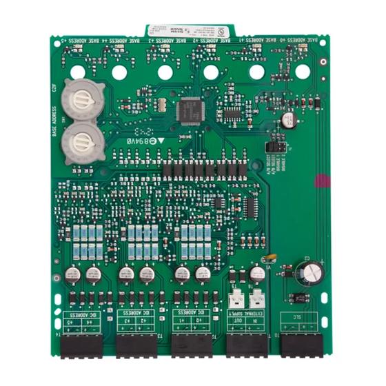
GENERAL DESCRIPTION
The CZ-6 Six Zone Interface Module is intended for use in an
intelligent alarm system. Each module provides an interface
between the intelligent alarm system and a conventional alarm
system loop. A common SLC input is used for all modules, and
the initiating device loops share a common supervisory supply
and ground. Otherwise, each monitor operates independently
from the others. Each module has its own unique address.
A pair of rotary code switches is used to set the address of the
first module from 01 to 94. The remaining modules are automati-
cally assigned to the next five higher addresses. Provisions are
included for disabling a maximum of two unused modules to
release the addresses to be used elsewhere. Each module also has
panel controlled by color LED indicators. The panel can cause the
LEDs to blink, latch on, or latch off.
BASE MODEL
B110LP, B401
B401, B401B
DH400
B110LP, B401
DH400, B401B, B401
B401, B401B
B401
N/A
N/A
N/A
N/A
N/A
N/A
N/A
N/A
N/A
N/A
N/A
N/A
N/A
N/A
N/A
N/A
1
Pittway Technologica S.p.A
Via Caboto 19/3
34147 Trieste, Italy
MAX DET.
20
20
20
20
20
20
20
20
20
20
20
20
20
20
20
20
20
20
20
20
20
20
20
I56-2256-01
Inhaltsverzeichnis

Verwandte Anleitungen für System Sensor CZ-6


Inhaltszusammenfassung für System Sensor CZ-6
-
Seite 10: Spezifikation
Zentrale gesteuerte, zweifarbige LED-Anzeige. Die ALLGEMEINES Zentrale kann die LED blinkend, folgend ein oder folgend aus Das CZ-6 Gruppenmodul wird in intelligenten ansteuern. Gefahrenmeldeanlagen eingesetzt. Jedes Modul verfügt Kompatible Zwei-Draht Sensor Rauchmelder für das CZ-6 Modul MELDER MELDER MODEL MEL. ID HERSTELLERSOCKEL MODELL MAX MELDERANZ. -
Seite 11: Verdrahtungshinweise
INSTALLIEREN SIE DIE MELDER GEMÄß DEN HERSTELLERVORGABEN DER INSTALLATIONSANLEITUNG Abbildung 1. Um eine gemeinsame Spannungsversorgung für mehrere CZ-6 Module einzusetzen, schliessen Sie das Steckkabel zur Spannungsversorgung von T5 oder T6 an T5 oder T6 des benachbarten CZ-6 Modules an. D500-67-00 I56-2256-01... - Seite 12 SPANNUNGSVERSORGUNG DARSTELLUNG A-A Abbildung 2: Beispiel zur gemeinsamen Spannungsversorgung mehrerer Module. Vergewissern Sie sich, dass der Stecker des Spannungskabels, wie in der Darstellung A-A gezeigt, fest in den Halteclip von T5 oder T6 einrastet. D500-67-00 I56-2256-01 © 2003 System Sensor...