Optex Smart Line serie Installationshinweise
Inhaltsverzeichnis
Verfügbare Sprachen
Verfügbare Sprachen
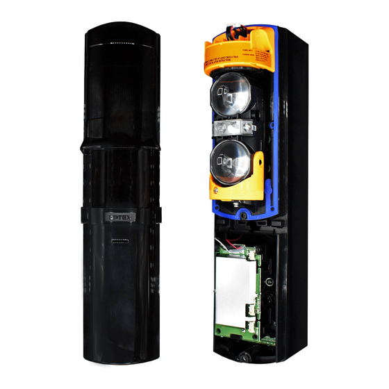
BATTERY OPERATED
BATTERY OPERATED
PHOTOELECTRIC DETECTOR
PHOTOELECTRIC DETECTOR
Smart Line series
Smart Line series
FEATURES
• Battery operated detector
- D size lithium battery or CR123A lithium battery
(OPTION CRH-5)
• Simplified optical adjustment
- Sniper View Finder with ×2 magnification
• Avoids having to install a wireless transmitter in the
photoelectric transmitter.
- IR signal transmission technology transfers the low
battery signal to the receiver
• Possible to connect the power and alarm cables to both
the receiver and the transmitter or either of them
- OPTION PCU-5
CONTENTS
1-1 BEFORE YOUR OPERATION ............................... 2
1-2 PRECAUTIONS...................................................... 3
1-3 PARTS IDENTIFICATION ...................................... 3
2 PREPARATIONS ......................................................... 4
3-1 SEPARATING ........................................................ 5
3-2 WALL MOUNTING ................................................ 5
3-3 POLE MOUNTING ................................................. 8
3-5 WIRING .................................................................. 9
INSTALLATION INSTRUCTIONS
™
™
MODEL
SL-100 TNR
SL-200 TNR
• Long battery life
• Battery saving function
• Intermittent output function
• Slim body design
• Easy to see vivid interior color for optical alignment
• IP65 waterproof structure
• Tamper function
• Indicator LED for an easy alignment
• Various options (Refer to "2 PREPARATIONS" and
"9 OPTIONS").)
(CRH-5, BCU-5, PCU-5)
4-1 FUNCTIONS......................................................... 11
4-2 OPTICAL ALIGNMENT ........................................ 12
5-1 LED INDICATION................................................. 13
5-2 OPERATION CHECK........................................... 13
6 TROUBLESHOOTING ............................................... 14
7 DIMENSIONS............................................................. 14
8 SPECIFICATIONS ..................................................... 15
9 OPTIONS ................................................................... 16
EN-1
No.59-2606-0 1701-16
DETECTION RANGE
30 m / 100 ft.
60 m / 200 ft.
Kapitel
Inhaltsverzeichnis
Fehlerbehebung

Verwandte Anleitungen für Optex Smart Line serie


Inhaltszusammenfassung für Optex Smart Line serie
-
Seite 33: Eigenschaften
INSTALLATIONSHINWEISE BATTERIEBETRIEBENE BATTERIEBETRIEBENE INFRAROT-LICHTSCHRANKEN INFRAROT-LICHTSCHRANKEN Smart Line Serie Smart Line Serie ™ ™ MODELL Erkennungsbereich SL-100 TNR 30 m / 100 ft. SL-200 TNR 60 m / 200 ft. EIGENSCHAFTEN • Batteriebetriebener Detektor • Lange Lebensdauer der Batterie - Lithium-Batterie D oder CR123A (optional CRH-5) •... -
Seite 34: Einleitung
EINLEITUNG VOR DER INBETRIEBNAHME • Dieses Handbuch vor der Installation sorgfältig durcharbeiten. • Das Handbuch an einem leicht zugänglichen Ort zum Nachschlagen aufbewahren. • In diesem Handbuch werden folgende Warnsymbole verwendet, um auf den korrekten Umgang mit dem Produkt sowie auf Gefahren für Sie oder weitere Personen und Sachschäden, wie im Folgenden beschrieben, hinzuweisen. Sie müssen diese Beschreibung verstanden haben, bevor Sie den Rest des Handbuchs durcharbeiten. -
Seite 35: Vorsichtsmassnahmen
VORSICHTSMASSNAHMEN Das Gerät nicht auf einer Pfosten nicht an einer Stelle Das Gerät nicht auf Bäumen, Den Empfänger nicht an instabilen Fläche montieren, an der keine zwischen Blättern oder anderen einer Stelle installieren, an installieren. ausreichende Stabilität gewährleistet Objekten installieren, die sich im der er direkter werden kann. -
Seite 36: Vorbereitungen
Zubehör 4x20 Blechschrauben Klettband: 1 Sets Kabel: 3 zur Wandmontage (mit Gummidichtung): 4 M4x16 Schrauben zur Pfostenmontage Pfostenhalterungen: 2 U-Halter: 2 (mit Gummidichtung): 4 VORBEREITUNGEN Senderseite Empfängerseite Schwache Batterie Alarm / Störungs Empfänger Sender Stromquelle Übertragung Übertragung Stromquelle ① trahlübertragung ①... -
Seite 37: Installation
INSTALLATION BAUTEILE TRENNEN Entfernen Sie das Gerätegehäuse. Ziehen Sie die Stecker ab. Entfernen Sie die Batterieabdeckung. Lösen Sie die Ziehen Lösen Sie die Ziehen Sicherungsschraube Sicherungsschraube der Batterieabdeckung. des Gerätegehäuses. Nehmen Sie das Grundgerät vom Rückkasten. Drehen Sie die Nehmen Sie das Grundgerät vom Rückkasten. Optikeinheit um 90°... - Seite 38 Montieren Sie das Rückkasten an der Wand. Seitenwand Abstand von der Seitenwand: mindestens 1 m Abstand: 83,5 mm Verbindung mit einem elektrischen Anschlusskasten 4x20 Blechschrauben (mit Gummidichtung) Befestigen Sie die Drahtlossender mittels Klettband im Rückkasten. Weitere Informationen zur Verkabelung finden Sie im Abschnitt 3-5 „VERKABELUNG“ . Schneiden Sie das im Lieferumfang enthaltene Klettband auf die...
-
Seite 39: Batterien Entsorgen
Schließen Sie die Stecker an. Hinweis>> • Vermeiden Sie eine Kabelführung, wo die Kabel im Gehäuse Grundgerät eingeklemmt werden können. Legen Sie die Batterien. • Wenden Sie das gleiche Verfahren für den Austausch von Batterien. < Verwendung von D-Batterien > 1 Öffnen Sie das Batteriefach in Pfeilrichtung. -
Seite 40: Pfostenmontage
Setzen Sie das Gerätegehäuse zurück. Setzen Sie die Batterieabdeckung zurück. Haken Sie das Oberteil am Setzen Sie die Batterieabdeckung zurück. Rückkasten ein. Drücken Sie das Unterteil des Gerätegehäuse an. Ziehen Sie die Sicherungsschraube der Batterieabdeckung an. Ziehen Sie die Sicherungsschraube des Gerätegehäuse an. -
Seite 41: Montagebeispiel: Sonderfall
Befestigen Sie den Rückkasten am Pfosten. Melder Nr. 2 Pfostenhalterungen U-Halter Melder Nr. 1 Seitenwand Abstand von der Seitenwand: mindestens 1 m M4x20 Schrauben (mit Gummidichtung) Pfosten 43 - 48 mm Durchmesser Folgen Sie der Wandmontage Punkt 3 bis 9 von "3-2 WANDMONTAGE". MONTAGEBEISPIEL: SONDERFALL Sender und Empfänger dürfen über die Ecken des Bei dieser Installation sollte der maximale Erkennungsbereich auf... - Seite 42 Anschluss an BCU-5 (optional) BCU-5 ermöglicht die gemeinsame Übertragung der Signale Spannungsversorgung und Batterie schwach zwischen dem Gerät und dem Sender. Weitere Informationen zum Anschluss finden Sie in der BCU-5-Bedienungsanleitung. Grundgerät Rückkasten BCU-5 Empfänger Batteriefach Schwarz EX EX – + Gelb Durch Orange...
-
Seite 43: Einstellungen
EINSTELLUNGEN FUNKTIONEN DIP-SCHALTER Siehe „1-3 ÜBERSICHT ÜBER DIE BAUTEILE“. Einstellschalter zur Infrarotstrahlunterbrechung 1 Einstellschalter zur Infrarotstrahlunterbrechung 2 Batteriestromspar-Timers Empfänger Schalter für die intermittierende Ausgabefunktion Hinweis>> POSITION DES • 'Drücken Sie nicht die Sabotagetaste, wenn Sie den WAHLSCHALTERS DIP-Schalter einstellen. Anderenfalls wird die Einstellung nicht geändert. -
Seite 44: Optische Ausrichtung
OPTISCHE AUSRICHTUNG Die optische Ausrichtung stellt einen wichtigen Schritt dar, um die Zuverlässigkeit zu erhöhen. Folgen Sie den Schritten 1 bis 2 , um mit der Überwachungsbuchse den maximalen Ausgangspegel einzustellen. Horizontaler Einstellwinkel Vertikaler Einstellwinkel 5° 5° 90° 90° Sehen Sie durch den Sucher und führen Sie die Feineinstellung der horizontalen und vertikalen Winkel mit Hilfe des Einstellrads zur optischen Ausrichtung durch. -
Seite 45: Funktionsprüfung
FUNKTIONSPRÜFUNG LED-ANZEIGE Alarm-/Pegel- LED (nur Empfänger) Hinweis>> • Der Betrieb der Alarm-/Pegel- LED wird nicht durch die Einstellung des Batteriestromspar-Timers geändert werden. Wenn der Strahl unterbrochen wird, leuchtet die LED. DETEKTOR Alarm-/Pegel- Strahlunterbrechung LEUCHTET Strahl nicht korrekt Blinkt schnell oder blinkt langsam empfangen Strahl korrekt empfangen... -
Seite 46: Fehlerbehebung
FEHLERBEHEBUNG PROBLEM MÖGLICHE URSACHE GEGENMASSNAHME Falsch eingelegte Batterien. Überprüfen Sie die Batteriepole. Betriebs-/Batterie-schwach-LEDs leuchten nicht. (Sender/Empfänger). Batterien laufen oder laufen aus. Ersetzen Sie alle Batterien. Richten Sie die Strahlen neu aus, weg Reflexion von Boden oder Wand. vom Boden oder von der Wand. Alarm wird nicht ausgegeben. -
Seite 47: Spezifikationen
SPEZIFIKATIONEN Modell SL-100TNR SL-200TNR Maximaler Erkennungsbereich 30 m 60 m Maximaler Erkennungsabstand 265 m 530 m Erkennungsverfahren Doppelte IR-Strahlunterbrechungs-Erkennung Unterbrechungszeit 50/100/250/500 ms wählbar 3,6 bis 3,9 V DC D-Lithium-Batterien jeweils für Sender und Empfänger: jeweils 2 (Empfohlen SB-D02HP von VITZROCELL) Stromquelle 3,0 V DC CR123A-Lithium-Batterien jeweils für Sender und Empfänger: jeweils 8 (Mit Betriebsbatteriehalter CRH-5: 2 Stück) -
Seite 48: Optionen
OPTEX SECURITY Sp.z o.o. (Poland) OPTEX (DONGGUAN) CO.,LTD. URL: http://www.optex.net/br/es/sec URL: http://www.optex.com.pl SHANGHAI OFFICE (China) URL: http://www.optexchina.com OPTEX (EUROPE) LTD. / EMEA HQ (U.K.) OPTEX PINNACLE INDIA, PVT., LTD. (India) URL: http://www.optex-europe.com URL: http://www.optex.net/in/en/sec OPTEX (Thailand) CO., LTD. (Thailand) URL: http://www.optex.net/th/th OPTEX TECHNOLOGIES B.V.