Herunterladen Inhalt Inhalt Diese Seite drucken

Werbung

Verfügbare Sprachen
  • DE

Verfügbare Sprachen

  • DEUTSCH, seite 11
www.fl eet.vdo.com
DLD
Wide Range II
®
Installation instructions

Werbung

Inhaltsverzeichnis
loading

Inhaltszusammenfassung für VDO DLD Wide Range II

  • Seite 1 Wide Range II ® Installation instructions...
  • Seite 2 Delivery content and accessories Delivery content Wide Range II ® Connecting cable, DTCO connector C, DTCO connector D, relevant PINs ® ® and product label (included) Installation instructions (7 languages) Accessories K-Line connecting cable; plug interface DTCO ® 1381 (see below) GPS antenna (article number: A2C59517075) Chip Card Reader for permanent access to the company card...
  • Seite 3 Table of Content Delivery content and accessories Connection overview Illustrations 4 – 9 Technical data and requirements Deutsch 11 – 50 Español 21 – 30 Français 31 – 40 English 41 – 50 Italiano 51 – 60 Nederlands 61 – 70 Pусский...
  • Seite 5: Connection Overview

    Connection overview Pos. Designation Start connection via DLD Wide Range II ® (DTCO ® to TIS-Web ® RTM) Feedback on company card signature Secure tachograph data transfer from DTCO to DLD via cable ® ® Encrypted data transfer from DLD ®...
  • Seite 6 Connection diagram – Power supply Pos. Designation Ignition (black) Permanent voltage (red) Ground (brown)
  • Seite 7 Connection diagram – CAN interface Pos. Designation DLD CAN1 (connect to DTCO CAN2) - CAN1 H - CAN1 L DLD CAN2 (connect to Vehicle CAN) - CAN2 H - FMS Interface - CAN2 L - FMS Interface CAN_RESISTOR (termination by cable bridge)
  • Seite 8 Location of DIP switches and LEDs Pos. Designation Termination CAN1 Termination CAN2...
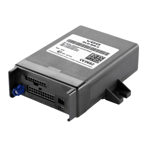
  • Seite 9 Location of LEDs DLD Satus LED 1 LED 2 LED 3 LED 4 LED 5 Power Boot not in use Sleep Mode Icon Designation green...
  • Seite 10 Technical data and requirements Wide Range II ® Dimensions L 30 x W 116 x H 40 mm Power supply in active mode: 9 V - 32 V ® in sleep mode: 6.5 V - 9 V ® Active mode: RMS consumption 300 mA at 12 V Current consumption Peak consumption: 2 A at 12 V Sleep mode: 6,5/ 32 mA at 12 V witthout/ with GSM...
  • Seite 11: Allgemeine Sicherheitshinweise

    Allgemeine Sicherheitshinweise Warnung: Gefahr durch Stromschlag Sämtliche Arbeiten am elektrischen Bordnetz dürfen nur von einer Fachwerkstatt ausgeführt werden. Warnung: Kurzschlussgefahr Beachten Sie bei allen Arbeitsschritten, insbesondere bei Arbeiten am Bordnetz, unbedingt die Hinweise des Fahrzeug- herstellers. Warnung: Achten Sie vor dem Trennen der Anschlussklemmen von der Batterie auf folgende Punkte: •...
  • Seite 12 Bereich von Ablagen oder von beweglichen Teilen, z. B. Airbag und Abdeckungen. Hinweis: Die Montagearbeiten und die Inbetriebnahme dürfen nur von Service-Technikern durchgeführt werden. Hinweis: Beachten Sie – zusätzlich zu den aufgeführten Hinweisen – auch die Service-Informationen im VDO Extranet http://extranet.vdo.com unter oder fragen Sie Ihren Service-Partner.
  • Seite 13: Vorbereitungen Und Voraussetzungen Für Die Montage

    Vorbereitungen und Voraussetzungen für die Montage Hinweis: Prüfen Sie anhand der Übersicht auf Seite 2 den Lieferumfang des DLD Wide Range II auf Vollständigkeit. ® Vorbereitungen DTCO – Vorbereitung durch autorisierte Vertragswerkstatt: ® • DTCO 1381 ab Release 1.3 ® •...
  • Seite 14: Voraussetzungen

    Wide Range II entsprechend konfi guriert ® (siehe hierzu „System requirements“) Hinweis: Beachten Sie – je nach Nutzungsumgebung – außerdem: • offizielle Service-Informationen im VDO Extranet unter http://extranet.vdo.com Tipp: Für detailliertere Informationen rund um die Konfi guration des DLD Wide Range II siehe auch die Online-Hilfe zu ®...
  • Seite 15: Erforderliche Anschlüsse Des ® Wide Range

    Erforderliche Anschlüsse des Wide Range II ® • Anschluss an die Spannungsversorgung • Anschluss an das Zündungssignal und an Masse • Anschluss zum Download der Daten über: - die CAN-Schnittstelle oder - die K-Line-Schnittstelle (Zubehör) Einbauorte des DLD Wide Range II ®...
  • Seite 16: Dld ® Wide Range Ii Einbauen

    Hinweis: Befestigen Sie die Leitungen in kurzen Abständen schwingungsfrei (ca. alle 500 mm). Hinweis: Achten Sie beim Einbau im Armaturenbrett auf die schnelle Ausbaumöglichkeit des DLD Wide Range II, z. B. ® für ein manuelles Firmware Upgrade oder den nachträglichen Anschluss einer Antenne.
  • Seite 17: Dld ® Wide Range Ii An Die Spannungsversorgung Im Fahrzeug Anschließen

    Hinweis: Beachten Sie unbedingt die Hinweise ab Seite 11 und Seite 15. 1. Befestigen Sie das DLD Wide Range II am vorgesehenen ® Einbauort. Verschrauben Sie das DLD Wide Range II mit ® zwei Schrauben oder kleben Sie es mit doppelseitigem Kle- beband fest.
  • Seite 18: Dld ® Wide Range Ii An Die Can-Schnittstelle Anschließen

    3. Schließen Sie die Zündungsspannung „Klemme 15“ an Pin 4 des Steckers an. 4. Schließen Sie die Masse-Anbindung „Klemme 31“ an Pin 1 des Steckers an. 5. Schließen Sie „Klemme 30“ an Pin 2 des Steckers an. Anschlussplan siehe Seite 6. Wide Range II an die CAN-Schnittstelle ®...
  • Seite 19: Optional: Dld ® Wide Range Ii An Die K-Line-Schnittstelle Anschließen

    Seite 8 zeigt des Weiteren den Abschlusswiderstand in zugeschalteter Position (Auslieferungszustand) und die Anordnung der DIP Switches. Optional: DLD Wide Range II an die ® K-Line-Schnittstelle anschließen Das K-Line-Kommunikationskabel (siehe Seite 9) ist nicht im Lieferumfang enthalten. Wenden Sie sich bitte an Ihren Service-Partner.
  • Seite 20 Test-Download Führen Sie einen Test-Download durch, um sicherzustellen, dass die Datenübertragung einwandfrei funktioniert. Voraussetzungen für eine Übertragung der Daten vom DTCO 1381 zum Computer: ® • Zugang zu TIS-Web ® • angeschlossener und betriebsbereiter Chipkartenleser • gesteckte, gültige Unternehmenskarte • ein am Computer angemeldeter Benutzer (zu dem die Tachographendaten übertragen werden sollen) Für die Authentisierungsaufgaben und die Kontrolle eines Downloads siehe Online-Hilfe zu TIS-Web...
  • Seite 21: Normas Generales De Seguridad

    Normas generales de seguridad Advertencia: Peligro por descarga eléctrica Todos los trabajos en el sistema eléctrico del vehículo deben ser realizados por un servicio técnico. Advertencia: Riesgo de cortocircuito En todos los trabajos, especialmente si se trata del sistema eléctrico, deben respetarse las instrucciones del fabricante del vehículo.
  • Seite 22 Nota: Además de las presentes indicaciones, debe tener en cuenta también las informaciones de servicio en la extranet (http://extranet.vdo.com) de VDO o consulte a su servicio de asistencia técnica. Nota: Deben cumplirse las normas y disposiciones para la prevención de accidentes laborales y las normas técnicas...
  • Seite 23 Preparativos y requisitos para el montaje Nota: Utilice la lista de la página 2 para comprobar la integridad del suministro del DLD Wide Range II. ® Preparativos DTCO – preparación por un centro técnico autorizado: ® • DTCO 1381 a partir de la versión 1.3 ®...
  • Seite 24 Nota: Además, dependiendo del entorno de uso, tenga en cuenta los puntos siguientes: • Informaciones ofi ciales de servicio en la extranet de (http://extranet.vdo.com) Sugerencia: Para obtener información más detallada sobre la confi guración del DLD Wide Range II, véase también la Ayuda ®...
  • Seite 25 Conexiones necesarias para el Wide Range II ® • Conexión a la alimentación eléctrica • Conexión a la señal de encendido y a masa • Conexión para la descarga de los datos a través de: - la interfaz CAN o - la interfaz K-Line (accesorio opcional) Lugar de montaje del Wide Range II...
  • Seite 26 Nota: Si hubiera mayores requisitos para el lugar de monta je, p. ej., debido a la humedad, vapores, aceite, etc., debería instalarse el DLD Wide Range II con la regleta de conexiones ® hacia abajo. Nota: Fije los cables en intervalos cortos y libres de vibraciones (cada 500 mm aprox.).
  • Seite 27 Nota: Deben cumplirse las instrucciones de las notas a partir de las páginas 21 y 25. 1. Fije el DLD Wide Range II en el lugar de montaje previsto. ® Atornille el DLD Wide Range II con dos tornillos o péguelo ®...
  • Seite 28 3. Conecte la tensión del encendido «terminal 15» al pin 4 del conector. 4. Conecte la conexión a masa «terminal 31» al pin 1 del conector. 5. Conecte el «terminal 30» al pin 2 del conector. Esquema de conexiones, véase la página 6. Conexión del DLD Wide Range II a la interfaz CAN ®...
  • Seite 29 Además, la página 8 muestra la resistencia de terminación en posición conectada (ajuste de fábrica) y la disposición de los interruptores DIP. Opcional: Conexión del DLD Wide Range II a la ® interfaz K-Line El cable de comunicación K-Line (véase la página 9) no está...
  • Seite 30 Descarga de prueba Realice una descarga de prueba para asegurarse de que la transferencia de datos funciona correctamente. Requisitos para una transferencia de datos del DTCO 1381 al ordenador: ® • Acceso a TIS-Web ® • Lector de tarjetas conectado y operativo •...
  • Seite 31: Consignes De Sécurité Générale

    Consignes de sécurité générale Avertissement : risque de choc électrique L’intégralité des travaux affectant le réseau de distribution de bord est à confi er à un atelier spécialisé. Avertissement : risque de court-circuit A chaque étape, et notamment lors de travaux affectant le réseau de distribution de bord, respectez scrupuleusement les consignes émanant du constructeur du véhicule.
  • Seite 32 Remarque : en plus des consignes mentionnées ici, observez également les notes de service disponibles sur l’extranet http://extranet.vdo.com VDO à l’adresse ou demandez conseil à votre centre partenaire agréé. Remarque : les règles et prescriptions en matière de prévention des accidents en vigueur dans votre pays ainsi...
  • Seite 33 Opérations préparatoires et conditions préalables au montage Remarque : veuillez vérifi er que l’ensemble des pièces et accessoires qui composent votre DLD Wide Range II, ® énumérés en des pages 2, vous ont bien été livrés. Préparatifs DTCO – opérations préparatoires à réaliser par un centre ®...
  • Seite 34: Conditions Requises

    Remarque : par ailleurs, et en fonction de l’environnement d’utilisation, il conviendra d’observer : • les notes de service officielles publiées sur l’extranet http://extranet.vdo.com VDO à l’adresse Conseil : pour plus d’informations sur la confi guration du Wide Range II, consultez également l’aide en ligne ®...
  • Seite 35 Raccordements nécessaires pour le Wide Range II ® • Raccordement à l’alimentation électrique • Raccordement au signal d’allumage et à la masse • Raccordement pour le téléchargement des données via : - l’interface CAN ou - l’interface K-Line (accessoire) Où installer le DLD Wide Range II ®...
  • Seite 36 Remarque : en cas de montage dans un environnement diffi cile, présence d’humidité, de vapeurs, d’huiles par ex., monter le DLD Wide Range II de sorte que le bloc de ® raccordement soit orienté vers le bas. Remarque : fi xer les câbles env. tous les 500 mm de sorte à...
  • Seite 37 Remarque : respectez impérativement les consignes fi gurant à partir de la des pages 31 et 34. 1. Fixer le DLD Wide Range II à l’emplacement prévu. Assurer ® la fi xation du DLD Wide Range II au moyen de deux vis ®...
  • Seite 38 3. Branchez la tension d’allumage « borne 15 » à la broche 4 du connecteur. 4. Branchez la liaison à la masse « borne 31 » à la broche 1 du connecteur. 5. Raccordez la « borne 30 » à la broche 2 du connecteur. Voir schéma de connexion, des pages 6.
  • Seite 39 Par ailleurs, à la des pages 8 vous pouvez voir la résis- tance de terminaison en position activée (état initial) ainsi que la disposition des commutateurs DIP. Facultatif : Raccordement du DLD Wide Range II ® à l’interface K-Line Le câble de communication K-Line (voir des pages 9) n’est pas fourni avec l’appareil.
  • Seite 40 Téléchargement test Pour vous assurer que le téléchargement fonctionne parfaitement, effectuez un téléchargement test. Conditions requises au transfert de données du DTCO 1381 vers l’ordinateur : ® • accès à TIS-Web ® • lecteur de cartes à puce branché et opérationnel •...
  • Seite 41: General Safety Notes

    General safety notes Warning: Risk of electric shock All work on the electrical system must only be carried out by a specialist workshop. Warning: Danger of short circuits Bear in mind that during all installation work (especially when working on the vehicle’s electrical system), the vehicle manu- facturer’s instructions must be adhered to.
  • Seite 42 Note: Installation and setup work may only be carried out by service technicians. Note: In addition to the above instructions, please also note the Service Information documents on the VDO Extranet at http://extranet.vdo.com or ask your service partner. Note: Please observe the rules and regulations (which apply in your country) for accident prevention and the recognised specialist technical rules for safe and professional working.
  • Seite 43 Preparing installation and installation requirements Note: Use the overview on page 2 to check that all the items in the DLD Wide Range II package are present. ® Preparatory steps DTCO – Preparation by an authorised workshop: ® • DTCO 1381 Release 1.3 or higher ®...
  • Seite 44 (see the “System requirements”) Note: Depending on the area of operation, please also note the following: • official Service Information documents on the VDO Extranet http://extranet.vdo.com Tip: For detailed information on how to confi gure the Wide Range II, please also refer to the TIS-Web RTM Help.
  • Seite 45 Required DLD Wide Range II ® connections • Connection to the power supply • Connection to the ignition signal and to earth • Connection to download the data via: - the CAN interface or - K-Line interface (accessory) Wide Range II installation ®...
  • Seite 46 Note: Fix the cables at short intervals (approx. every 500 mm) so that they do not vibrate. Note: When installing into the dashboard, make sure that the Wide Range II can be removed quickly, e.g. to carry out a ® manual fi...
  • Seite 47 Note: Please observe the notes from page 41 and page 45 without fail. 1. Fix the DLD Wide Range II in the installation location. Screw ® on the DLD Wide Range II with two screws or fi x it with dou- ®...
  • Seite 48 3. Connect “Terminal 15” (ignition voltage) to connector pin 4. 4. Connect “Terminal 31” (ground) to connector pin 1. 5. Connect “Terminal 30” to connector pin 2. See the wiring diagram on page 6. Connecting the DLD Wide Range II to the CAN ®...
  • Seite 49 Page 8 also shows the activated termination resistor (status upon delivery) and the DIP switch location. Optional: Connecting the DLD Wide Range II ® to the K-Line interface The K-Line communication cable (see page 9) is not included in the package. Please contact your service partner. Wide Range II –...
  • Seite 50 Test download Carry out a test download to ensure that the data is being transferred correctly. Requirements for the data transfer from the DTCO 1381 to the computer: ® • Access to TIS-Web ® • Chip card reader (connected and operational) •...
  • Seite 51: Indicazioni Generali Sulla Sicurezza

    Indicazioni generali sulla sicurezza Avvertenza: pericolo di scarica elettrica Tutti i lavori alla rete di bordo elettrica devono essere eseguiti solo da un'offi cina specializzata. Avvertenza: pericolo di cortocircuito Specialmente per i lavori alla rete di bordo, attenersi assoluta- mente alle rispettive indicazioni della casa automobilistica. Avvertenza: prima di scollegare i morsetti dalla batteria, svolgere le seguenti operazioni: •...
  • Seite 52 Nota: l'installazione e la messa in funzione devono essere eseguite solo da tecnici specializzati. Nota: attenersi non solo alle indicazioni elencate, ma anche alle informazioni sui servizi riportate in VDO Extranet su http://extranet.vdo.com oppure rivolgersi al partner di servizio. Nota: attenersi alle norme e disposizioni nazionali in vigore in materia di antinfortunistica e ai regolamenti riconosciuti per lavorare in modo professionale e sicuro.
  • Seite 53: Operazioni Preliminari

    Operazioni preliminari e requisiti per il montaggio Nota: a mezzo del sommario a a pagg 2, verifi care la completezza della confezione del DLD Wide Range II. ® Operazioni preliminari DTCO – Preparazione a cura dell'offi cina autorizzata: ® • DTCO 1381 a partire dalla release 1.3 ®...
  • Seite 54 Nota: secondo l'ambiente di utilizzo, è inoltre necessario che: • siano osservate le informazioni uffi ciali sui servizi in http://extranet.vdo.com VDO Extranet su Suggerimento: per informazioni esaustive sulla confi gurazio- ne del DLD Wide Range II, vedi anche la guida online ®...
  • Seite 55 Connessioni necessarie del Wide Range II ® • Connessione all'alimentazione di tensione • Connessione al segnale di accensione e alla massa • Connessione per il download dei dati tramite: - interfaccia CAN o - interfaccia K-Line (accessori) Luogo di installazione del Wide Range II ®...
  • Seite 56 Nota: fi ssare i cavi a poca distanza tra loro, isolati da qualsiasi vibrazione (circa ogni 500 mm). Nota: il montaggio nel cruscotto consente il rapido smontaggio del DLD Wide Range II, ad es. per l'aggiornamento manuale ® del fi rmware o per la connessione a posteriore di un'antenna. Suggerimento: proteggere le aperture destinate agli interrut- tori DIP e l'interfaccia USB contro l'infi...
  • Seite 57 Nota: attenersi assolutamente alle indicazioni da a pagg 51 a 55. 1. Fissare il DLD Wide Range II nel luogo di installazione ® scelto. Avvitare il DLD Wide Range II con due viti o fi ssarlo ® con nastro adesivo bilaterale. Controllare periodicamente che l'adesione sia ancora intatta.
  • Seite 58 3. Collegare la tensione di accensione (morsetto 15) al pin 4 del connettore. 4. Collegare la messa a terra (morsetto 31) al pin 1 del connettore. 5. Collegare il morsetto 30 al pin 2 del connettore. Vedi schema elettrico a pagg 6. Collegamento del DLD Wide Range II ®...
  • Seite 59 A pagg 8 si riferisce inoltre al resistore di terminazione in posizione attivata (stato alla consegna) e alla confi gurazione degli interruttori DIP. Opzione: Collegamento del DLD Wide Range II ® all'interfaccia K-Line Il cavo di trasmissione dati K-Line (vedi a pagg 9) non è fornito con la dotazione.
  • Seite 60 Download di prova Eseguire un download di prova per verifi care che il trasferimento dati avvenga senza problemi. Requisiti per il trasferimento dati tra DTCO 1381 ® e computer: • accesso a TIS-Web ® • lettore di carte chip collegato e pronto all'uso •...
  • Seite 61: Algemene Veiligheidsinstructies

    Algemene veiligheidsinstructies Waarschuwing: gevaar door elektrische schok! Alle werkzaamheden aan het boordnet moeten worden uitgevoerd door een vakgarage. Waarschuwing: risico van kortsluiting! Houd bij alle processen, vooral bij werkzaamheden aan het boordnet, rekening met de instructies van de fabrikant van het voertuig.
  • Seite 62 Aanwijzing: de montagewerkzaamheden en de inbedrijfstel- ling mogen alleen door servicepersoneel worden uitgevoerd. Aanwijzing: houd ook rekening - aanvullend bij bovenstaande instructies - met de service-informatie van het VDO Extranet http://extranet.vdo.com of vraag uw servicepartner. Aanwijzing: houd bovendien rekening met de in uw land gel- dende regels en voorschriften voor ongevallenpreventie en de erkende regels voor veilig en vakkundig werken.
  • Seite 63 Voorbereidingen en vereisten voor montage Aanwijzing: controleer aan de hand van het overzicht op 2 of de levering van de DLD Wide Range II volledig is. ® Voorbereidingen DTCO – voorbereiding door geautoriseerde vakgarage: ® • DTCO 1381 vanaf release 1.3 ®...
  • Seite 64 ® (zie “System requirements”) Aanwijzing: houd bovendien – afhankelijk van de gebruiksom- geving – rekening met: • de officiële service-informatie van het VDO Extranet http://extranet.vdo.com Tip: zie voor meer gedetailleerde informatie over de confi gu- ratie van de DLD Wide Range II ook de online help van ®...
  • Seite 65 Vereiste aansluitingen van de Wide Range II ® • Aansluiting op de voeding • Aansluiting aan het contactsignaal en aan massa • Aansluiting voor het downloaden via: - de CAN-bus of - de K-Line-interface (toebehoren) Inbouwlocaties van de Wide Range II ®...
  • Seite 66 Aanwijzing: bevestig de kabels met korte afstanden ertussen (ca.500 mm) en zonder oscillatie. Aanwijzing: houd bij het inbouwen in het dashboard rekening met de mogelijkheid de DLD Wide Range II weer snel uit te ® kunnen bouwen, bijv. voor een handmatige fi rmware-upgrade of latere aansluiting van een antenne.
  • Seite 67 Aanwijzing: volg altijd de instructies vanaf 61 en 65. 1. Monteer de DLD Wide Range II op de gekozen inbouwloca- ® tie. Schroef de DLD Wide Range II met twee schroeven ® vast of plak hem vast met dubbelzijdig plakband. Controleer regelmatig of de montage met plakband nog intact is.
  • Seite 68 3. Sluit de contactspanning “klem 150” aan pin 4 van de stekker aan. 4. Sluit de massaverbinding “klem 31” aan pin 1 van de stekker aan. 5. Sluit “klem 30” aan pin 2 van de stekker aan. Voor aansluitschema zie 6. Wide Range II aan de CAN-bus aansluiten ®...
  • Seite 69 8 toont bovendien de afsluitweerstand in de aangesloten positie (fabrieksinstelling) en de confi guratie van de DIP-schakelaars. Optioneel: DLD Wide Range II aan de ® K-Line-interface aansluiten De K-Line-communicatiekabel (zie 9) hoort niet bij de leveringsomvang. Neem contact op met uw servicepartner. LED-indicatie van de Wide Range II ®...
  • Seite 70 Test-download Probeer een test-download om er zeker van te zijn dat de gegevensoverdracht feilloos functioneert. Vereisten voor gegevensoverdracht van de DTCO 1381 naar de computer: ® • toegang tot TIS-Web ® • aangesloten en bedrijfsklare chipkaartlezer • geplaatste, geldige bedrijfskaart •...
  • Seite 71: Общие Указания По Технике Безопасности

    Общие указания по технике безопасности Предупреждение: Угроза из-за поражения электрическим током Все работы на электрической бортовой сети разрешается выполнять только специалистам. Предупреждение: Угроза короткого замыкания Во время выполнения любых работ, в частности, на элек- трической бортовой сети, следует тщательно соблюдать инструкции...
  • Seite 72 решается выполнять только техническим специалистам по обслуживанию. Указание: Выполняйте - в дополнение к представленным указаниями - также инструкции Информации по обслужи- ванию во внешней сети VDO, которая выложена по адресу http://extranet.vdo.com , или же обращайтесь с вопросами к Вашему сервис-партнеру.
  • Seite 73 Подготовка и условия для выполнения монтажа Указание: Проверьте упаковку на комплектность в соответствии с перечнем поставки, указанным на 2 для DLD Wide Range II. ® Подготовка DTCO – Подготовка с помощью авторизованного ® мастерской: • DTCO 1381, начиная с версии 1.3 ®...
  • Seite 74 Wide Range II ® (см. «System requirements / Системные требования») Указание: Дополнительно, следует учитывать, в зависимости от среды использования: • официальную сервисную информацию во внешней http://extranet.vdo.com сети Совет: Для получения подробной информации о конфигурации DLD Wide Range II обращайтесь также ®...
  • Seite 75 Необходимые подключения для Wide Range II ® • Подключение к сети напряжения • Подключение к сигналу зажигания и массы • Подключение к загрузке данных с помощью: - разъема CAN - разъема K-Line (аксессуары) Место для монтажа Wide Range II ® Место...
  • Seite 76 Указание: В соответствии с §35b Правил о допуске к до- рожному движению водитель должен обеспечить достаточ- ную видимость с учетом всех рабочих и погодных условий. Указание: При усложнении условий на месте монтажа, на- пример, из-за высокой влажности, пара, масел, соедини- тельная...
  • Seite 77 Монтаж DLD Wide Range II ® Условия • Место установки выбрано • Конфигурация DLD Wide Range II выполнена ® • Проложен кабель для подачи питания и разъемы CAN Указание: Обязательно выполняйте указания от 71 и 75. 1. Зафиксируйте DLD Wide Range II на предусмо- ®...
  • Seite 78 3. Подключите напряжение зажигания «зажима 15» на вилку 4 штекера. 4. напряжение массы «зажима 31» на вилку 1 штекера. 5. Подключите «зажим 30» на вилку 2 штекера. См. на 6 план подключения. Подключите DLD Wide Range II к разъему CAN ®...
  • Seite 79 Дополнительно, на 8, предоставляется значение нагрузочного сопротивления в выключенном положении (исходном положении). Настройка переключателя DIP. Дополнительно: Подключите Wide Range II к разъему K-Line ® Кабель связи K-Line (см. 9) не входит в комплектацию. Пожалуйста, обратитесь к Вашему сервис-партнеру. ЖК-индикаторы DLD Wide Range II ®...
  • Seite 80 Тестовая загрузка Выполните тестовую загрузку, чтобы убедиться в свободной передаче данных. Условиями для передачи данных из DTCO 1381 на компьютер являются: ® • наличие доступа к TIS-Web ® • наличие подключенного и работающего считывателя карт • вставленная, действительная карта предприятия •...
  • Seite 81: System Requirements

    System requirements Software Operating system Microsoft Windows 7 (32- and 64-Bit), ® ® Microsoft Windows 8 (32- and 64-Bit) ® ® Microsoft Windows 10 (32- and 64-Bit ® ® Browser Google Chrome from version 24 (32- and 64-Bit) ® Microsoft Internet Explorer from version 10 ®...
  • Seite 82 Disclaimer Haftungsausschluss Die Produzenten übernehmen keine Haftung für Schäden, die durch eine bestimmungswidrige Verwendung entstehen, insbesondere nicht für Personen-, Sach- oder Vermögensschäden, die als Folgeschäden unmit- telbar im Zusammenhang mit der bestimmungswidrigen Verwendung des Wide Range II in Verbindung stehen. ®...
  • Seite 83 Disclaimer Esclusione della responsabilità Il produttore declina qualsiasi responsabilità per danni dovuti all‘uso non conforme alle disposizioni, in particolare per le lesioni personali e i danni materiali o patrimoniali direttamente o indirettamente causati dall‘uso non conforme alle disposizioni del DLD Wide Range II.
  • Seite 84 Germany www.fl eet.vdo.com tachograph@vdo.com VDO – A trademark of the Continental Corporation The information contained in this documentation is subject to change without prior notice. In doing so, Continental Automotive GmbH do not enter into any obligation. The description is based on the information available at the time this documentation was printed.

Inhaltsverzeichnis