Herunterladen Inhalt Inhalt Diese Seite drucken

Werbung

Verfügbare Sprachen
  • DE

Verfügbare Sprachen

  • DEUTSCH, seite 4
EDK94AYAF
.T]N
L−force Drives
9400
E94AYAF − SM302
Sicherheitsmodul
Safety module
Module de sécurité
Módulo de seguridad
Modulo di sicurezza
Montageanleitung
Mounting Instructions
Instructions de montage
Instrucciones para el montaje
Istruzioni per il montaggio
l

Werbung

Inhaltsverzeichnis
loading

Inhaltszusammenfassung für Lenze SM302

  • Seite 1 EDK94AYAF L−force Drives .T]N Montageanleitung Mounting Instructions Instructions de montage Instrucciones para el montaje Istruzioni per il montaggio 9400 E94AYAF − SM302 Sicherheitsmodul Safety module Module de sécurité Módulo de seguridad Modulo di sicurezza...
  • Seite 2 Lesen Sie zuerst diese Anleitung und die Dokumentation zum Grundgerät, bevor Sie mit den Arbeiten beginnen! Beachten Sie die enthaltenen Sicherheitshinweise. Please read these instructions and the documentation of the standard device before you start working! Observe the safety instructions given therein! Lire le présent fascicule et la documentation relative à...
  • Seite 3 SSP94SM321b...
  • Seite 4: Elemente Auf Der Vorderseite

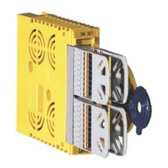
    Lieferumfang Pos. Beschreibung Sicherheitsmodul SM302, Typ E94AYAF Montageanleitung Elemente auf der Vorderseite Pos. Beschreibung Safety−Adressschalter (in der linken Gehäuseseite) Modultaster zur Parametersatzübernahme vom Speichermodul X82.1 X82.2 Steckbare Klemmleisten für Eingangssignale und Ausgangssignale X82.3 X82.4 EDK94AYAF DE/EN/FR/ES/IT 1.0...
  • Seite 5 Anzeigen Pos. Farbe Zustand Beschreibung Integrierte Sicherheitstechnik ist fehlerfrei initialisiert. Integrierte Sicherheitstechnik ist fehlerfrei initialisiert. Die interne Kommunikation zum Grundgerät ist nicht blinkt möglich. grün Integrierte Sicherheitstechnik ist im Service−Zustand. (Module State) blitzt Zum Verlassen die integrierte Sicherheitstechnik para- metrieren. Integrierte Sicherheitstechnik ist nicht initialisiert.
  • Seite 6: Montage

    Montage E94AYAX001 Demontage E94AYCXX001H EDK94AYAF DE/EN/FR/ES/IT 1.0...
  • Seite 7 1.0 Identifikation „ Type  ‚ ƒ E94YCEI003C E94AYXX001  ‚ ƒ „ Produktreihe Gerätegeneration Modulkennung: Gerätemodul Modultyp: Sicherheitsmodul Ausführung A = SM0 B = SM100 E = SM301 F = SM302 Hardwarestand Softwarestand (nur SM30x) Seriennummer EDK94AYAF DE/EN/FR/ES/IT 1.0...
  • Seite 8 Einsetzbarkeit Die Verwendung dieses Moduls ist zulässig mit Grundgeräten der Produktreihe 9400 ab dem Typenschildaufdruck Type E94AxHExxxx 13.xx E94BSHExxxx − E94AxPExxxx 07.xx E94BSPExxxx − Die Verwendung dieses Moduls ist zulässig mit Kommunikationsmodul PROFINET® ab dem Typenschildaufdruck Type E94AYCER 03.xx Die Verwendung dieses Moduls ist zulässig mit Kommunikationsmodul EtherCAT® ab dem Typenschildaufdruck Type E94AYCET...
  • Seite 9: Sicherheitshinweise

    Sicherheitshinweise Verwendete Hinweise Sicherheitshinweise Verwendete Hinweise Um auf Gefahren und wichtige Informationen hinzuweisen, werden in dieser Dokumenta- tion folgende Piktogramme und Signalwörter verwendet: Sicherheitshinweise Aufbau der Sicherheitshinweise: Gefahr! (kennzeichnet die Art und die Schwere der Gefahr) Hinweistext (beschreibt die Gefahr und gibt Hinweise, wie sie vermieden werden kann) Piktogramm und Signalwort Bedeutung Gefahr von Personenschäden durch gefährliche elektri-...
  • Seite 10 Sicherheitshinweise Verwendete Hinweise Anwendungshinweise Piktogramm und Signalwort Bedeutung Wichtiger Hinweis für die störungsfreie Funktion Hinweis! Nützlicher Tipp für die einfache Handhabung Tipp! Verweis auf andere Dokumentation Spezielle Sicherheitshinweise und Anwendungshinweise Piktogramm und Signalwort Bedeutung Warnings! Sicherheitshinweis oder Anwendungshinweis für den Betrieb nach UL−...
  • Seite 11: Allgemeine Sicherheitshinweise

    Sicherheitshinweise Allgemeine Sicherheitshinweise Allgemeine Sicherheitshinweise Gefahr! Unsachgemäßer Umgang mit dem Modul und dem Grundgerät kann schwere Personenschäden und Sachschäden verursachen. Beachten Sie die in den Anleitungen zum Grundgerät enthaltenen Sicherheitshinweise und Restgefahren. Gefahr! Wird die Anforderung für die Sicherheitsfunktion aufgehoben, kann der Antrieb automatisch wieder anlaufen.
  • Seite 12 Sicherheitshinweise Allgemeine Sicherheitshinweise Beachten Sie unbedingt die folgenden Sicherheitshinweise und Anwendungshinweise, um die zertifizierten Eigenschaften der Sicherheitstechnik zu erhalten und den störungsfreien und gefahrlosen Betrieb zu gewährleisten. Restgefahren Bei Kurzschluss zweier Leistungstransistoren kann am Motor eine Restbewegung von bis zu 180 °/Polpaarzahl auftreten! (Bsp.: 4poliger Motor Þ Restbewegung max. 180 °/2 = 90 °) Diese Restbewegung muss der Anwender bei seiner Risikoanalyse berücksichtigen, z.
  • Seite 13 Sicherheitshinweise Sicherheitshinweise für die Installation nach UL/CSA Sicherheitshinweise für die Installation nach UL/CSA Warnings! Secondary circuit shall supplied from an external isolating source. ƒ Maximum surrounding air temperature: 55 °C. ƒ EDK94AYAF DE/EN/FR/ES/IT 1.0...
  • Seite 14: Technische Daten

    Technische Daten Technische Daten 24−V−Versorgung Die 24−V−Versorgung des Moduls und des sicheren Ausgangs muss aus sicher getrennten Netzteilen erfolgen. Ist Potenzialtrennung erforderlich, müssen getrennte Spannungsver- sorgungen verwendet werden. Detaileigenschaften der 24−V−Versorgung Klemme Spezifikation [Einheit] min. typ. max. +, − Versorgungsspannung Modul durch ein sicher 19.2 getrenntes Netzteil (SELV/PELV) Eingangsstrom...
  • Seite 15: Elektrische Installation

    Bei der Installation die Dokumentation des Antriebsreglers beachten. Adressierung Die Safety−Adresse dient der eindeutigen Zuordnung der Sicherheitsmodule des Typs SM302 in Anlagen mit mehreren Antrieben. Die Adresse "0" ist nicht zulässig. Adress−Schalter Die Safety−Adresse kann mit dem DIP−Schalter 0 in der linken Gehäuseseite eingestellt werden.
  • Seite 16 Elektrische Installation Klemmenbelegung Hinweis! Sorgen Sie für ausreichende Zugentlastung, damit die Klemmen nicht aus den Stiftleisten gezogen werden, insbesondere wenn Sie starre Leitungen verwenden. X82.1 Beschriftung Beschreibung Dieser Teil der Klemmleiste ist nicht belegt. GND SD−Out1 Sichere Rückmeldung SD−Out1, Kanal B Sichere Rückmeldung SD−Out1, Kanal A Dieser Teil der Klemmleiste ist nicht belegt.
  • Seite 17 Elektrische Installation X82.3 Beschriftung Beschreibung GND Taktausgang GND SD−In2 Sensoreingang SD−In2, Kanal B Sensoreingang SD−In2, Kanal A GND Taktausgang GND SD−In1 Sensoreingang SD−In1, Kanal B Sensoreingang SD−In1, Kanal A Wiederanlaufquittierungseingang ("Acknowledge In Stop", 1−kana- lig, gebrückt zu X82.4/AIS) X82.4 Beschriftung Beschreibung GND Taktausgang GND SD−In4...
  • Seite 18 Scope of supply Pos. Description SM302 safety module, type E94AYAF Mounting Instructions Elements on the front Pos. Description Safety address switch (in the left part of the housing) Module switch for parameter set adoption from the memory module X82.1 X82.2 Plug−in terminal strips for input and output signals...
  • Seite 19 Displays Pos. Colour State Description Drive−based safety has initialised without a fault. Drive−based safety has initialised without a fault. Internal communication to the standard device is not Blinking possible. Green Drive−based safety is in service status. (Module State) Flashing For exiting, parameterise the drive−based safety. Drive−based safety is not initialised.
  • Seite 20 Mounting E94AYAX001 Dismounting E94AYCXX001H EDK94AYAF DE/EN/FR/ES/IT 1.0...
  • Seite 21: Validity Information

    Validity information This documentation is valid for: SM302 safety module Type E94AYAF from VA As of 1.0 Identification „ Type  ‚ ƒ E94YCEI003C E94AYXX001  ‚ ƒ „ Product series Version Module identification: Device module Module type: Safety module...
  • Seite 22: Application Range

    Application range The use of this module is permissible with standard devices of the 9400 product series from nameplate designation Type E94AxHExxxx 13.xx E94BSHExxxx − E94AxPExxxx 07.xx E94BSPExxxx − The use of this module is permissible with the PROFINET® communication module from nameplate designation Type E94AYCER...
  • Seite 23: Safety Instructions

    Safety instructions Notes used Safety instructions Notes used The following pictographs and signal words are used in this documentation to indicate dangers and important information: Safety instructions Structure of safety instructions: Danger! (characterises the type and severity of danger) Note (describes the danger and gives information about how to prevent dangerous situations) Pictograph and signal word...
  • Seite 24 Safety instructions Notes used Application notes Pictograph and signal word Meaning Important note to ensure troublefree operation Note! Useful tip for simple handling Tip! Reference to another documentation Special safety instructions and application notes Pictograph and signal word Meaning Warnings! Safety note or application note for the operation according to UL or CSA requirements.
  • Seite 25: General Safety Information

    Safety instructions General safety information General safety information Danger! Improper use of the module and the standard device may cause serious injury and property damage. Observe the chapters "Safety instructions" and "Residual hazards" contained in the instructions for the standard device. Danger! When the request for the safety function is deactivated, the drive can restart automatically.
  • Seite 26 Safety instructions General safety information Please observe the following safety instructions and application notes to preserve the certified safety engineering features and to ensure trouble−free and safe operation. Residual hazards In case of a short−circuit of two power transistors a residual movement of the motor of up to 180 °/number of pole pairs may occur! (Example: 4−pole motor Þ...
  • Seite 27 Safety instructions Safety instructions for the installation according to UL/CSA Safety instructions for the installation according to UL/CSA Warnings! Secondary circuit shall supplied from an external isolating source. ƒ Maximum surrounding air temperature: 55 °C. ƒ EDK94AYAF DE/EN/FR/ES/IT 1.0...
  • Seite 28: Technical Data

    Technical data Technical data 24 V supply The module and the safe output must be supplied with 24 V from safely separated power supply units. If electrical isolation is required, separate voltage supplies must be used. Detailed features of the 24−V supply Terminal Specification [Unit]...
  • Seite 29: Electrical Installation

    For installation, the documentation of the controller must be observed. Addressing The safety address serves to the clear assignment of the safety modules of the SM302 type in systems with several drives. The address "0" is not permissible. Address switch The safety address can be set in the left part of the housing by means of the DIP switch 0.
  • Seite 30 Electrical installation Terminal assignment Note! Provide for a sufficient strain relief, so that the terminals are not pulled from the plug connectors, in particular when you use rigid cables. X82.1 Labelling Description This part of the terminal strip is not assigned. GND SD−Out1 Safe monitor SD−Out1, channel B Safe monitor SD−Out1, channel A...
  • Seite 31 Electrical installation X82.3 Labelling Description GND clock output GND SD−In2 Sensor input SD−In2, channel B Sensor input SD−In2, channel A GND clock output GND SD−In1 Sensor input SD−In1, channel B Sensor input SD−In1, channel A Restart acknowledgement input ("Acknowledge In Stop", 1−channel, bridged to X82.4/AIS) X82.4 Labelling...
  • Seite 32: Équipement Livré

    Équipement livré Pos. Description Module de sécurité SM302, type E94AYAF Instructions de montage Eléments à l’avant Pos. Description Interrupteur d’adressage de sécurité (sur le côté gauche du boîtier) Bouton−poussoir du module pour valider le jeu de paramètres du module de mémoire X82.1...
  • Seite 33 Affichages Pos. Couleur Etat Description Le module de sécurité intégré a été correctement initialisé. Le module de sécurité intégré a été correctement CLIGNOTE initialisé, mais la communication interne avec l’appareil de base est impossible. LED verte (Module State) Le module de sécurité intégré est à l’état "service". SCINTILLE Paramétrer le module de sécurité...
  • Seite 34 Montage E94AYAX001 Démontage E94AYCXX001H EDK94AYAF DE/EN/FR/ES/IT 1.0...
  • Seite 35 Validité Le présent document s’applique au produits suivants : Module de sécurité SM302 Type Matériel Logiciel E94AYAF A partir de VA A partir de 1.0 Identification „ Type  ‚ ƒ E94YCEI003C E94AYXX001  ‚ ƒ „ Série d’appareils Génération d’appareils Identification du module : module d’appareil...
  • Seite 36: Remarque Importante

    Utilisation Le module est compatible avec les appareils de base série 9400 de la version suivante (indications sur plaque signalétique) : Type Matériel Logiciel E94AxHExxxx 13.xx E94BSHExxxx − E94AxPExxxx 07.xx E94BSPExxxx − Ce module est compatible avec le module de communication PROFINET® à partir de la version suivante (indications sur la plaque signalétique) Type Matériel...
  • Seite 37: Consignes De Sécurité

    Consignes de sécurité Consignes utilisées Consignes de sécurité Consignes utilisées Pour indiquer des risques et des informations importantes, la présente documentation utilise les mots et pictogrammes suivants : Consignes de sécurité Présentation des consignes de sécurité Danger ! (Le pictogramme indique le type de risque.) Explication (L’explication décrit le risque et les moyens de l’éviter.) Pictogramme et mot associé...
  • Seite 38 Consignes de sécurité Consignes utilisées Consignes d’utilisation Pictogramme et mot associé Explication Remarque Remarque importante pour assurer un fonctionnement correct importante ! Conseil utile pour faciliter la mise en œuvre Conseil ! Renvoi à une autre documentation Consignes de sécurité et d’utilisation spéciales Pictogramme et mot associé...
  • Seite 39: Consignes Générales De Sécurité

    Consignes de sécurité Consignes générales de sécurité Consignes générales de sécurité Danger ! Toute utilisation contre−indiquée du module et de l’appareil de base risque d’entraîner des blessures et des dommages matériels graves. Tenir compte des consignes de sécurité et des dangers résiduels décrits dans la documentation de l’appareil de base concerné.
  • Seite 40 Consignes de sécurité Consignes générales de sécurité Respecter impérativement les consignes de sécurité et les indications d’utilisation suivantes afin de garantir les caractéristiques de sécurité certifiées et d’assurer un fonctionnement fiable et sans danger. Dangers résiduels En cas de court−circuit entre deux transistors de puissance, un mouvement résiduel max. équivalent à...
  • Seite 41 Consignes de sécurité Consignes de sécurité pour l’installation selon UL / CSA Consignes de sécurité pour l’installation selon UL / CSA Avertissements ! Prévoir un circuit auxiliaire alimenté par une source de tension avec ƒ isolation galvanique. Température ambiante maximale : 55 °C. ƒ...
  • Seite 42: Spécifications Techniques

    Spécifications techniques Spécifications techniques Alimentation 24 V L’alimentation 24 V du module et de la sortie sûre doit être assurée par des blocs d’alimentation avec coupure de sécurité. Si une séparation de potentiel est nécessaire, il faut avoir recours à des alimentations séparées. Caractéristiques détaillées de l’alimentation 24 V Borne Spécification...
  • Seite 43: Installation Électrique

    Pour l’installation, tenir compte des indications contenues dans la documentation du variateur de vitesse. Adressage L’adresse de sécurité sert à l’affectation univoque des modules de sécurité de type SM302 dans les installations dotées de plusieurs entraînements. L’adresse "0" n’est pas autorisée. Interrupteur d’adressage L’adresse de sécurité...
  • Seite 44 Installation électrique Affectation des bornes Remarque importante ! S’assurer que le support de charge est suffisant pour éviter de retirer les bornes des connecteurs à broches, en particulier en cas d’utilisation de câbles fixes. X82.1 Inscription Description Cette partie du bornier n’est pas affectée. GND SD−Out1 Information d’état sûre SD−Out1, canal B Information d’état sûre SD−Out1, canal A...
  • Seite 45 Installation électrique X82.3 Inscription Description GND : sortie pulsée GND : SD−In2 Entrée pour capteur SD−In2, canal B Entrée pour capteur SD−In2, canal A GND : sortie pulsée GND : SD−In1 Entrée pour capteur SD−In1, canal B Entrée pour capteur SD−In1, canal A Entrée pour l’acquittement de redémarrage ("Acknowledge In Stop", un canal, pontée vers X82.4/AIS) X82.4...
  • Seite 46: Contenido Del Suministro

    Contenido del suministro Pos. Descripción Módulo de seguridad SM302, tipo E94AYAF Instrucciones para el montaje Elementos en la parte delantera Pos. Descripción Interruptor de dirección de seguridad (en el lado izquierdo de la carcasa) Tecla de módulo para la aceptación de parámetros del módulo de memoria X82.1...
  • Seite 47 Indicadores Pos. Color Estado Descripción La técnica de seguridad integrada se ha inicializado encendido libre de errores. La técnica de seguridad integrada se ha inicializado parpadea libre de errores. No es posible una comunicación interna con el equipo básico. verde La técnica de seguridad integrada está...
  • Seite 48: Montaje

    Montaje E94AYAX001 Desmontaje E94AYCXX001H EDK94AYAF DE/EN/FR/ES/IT 1.0...
  • Seite 49 Vigencia de la información Esta documentación es válida para: Módulo de seguridad SM302 Tipo E94AYAF a partir de VA a partir de 1.0 Identificación „ Type  ‚ ƒ E94YCEI003C E94AYXX001  ‚ ƒ „ Serie de productos Generación de equipos Identificación del módulo: módulo de...
  • Seite 50 Posibilidades de uso Está permitido utilizar este módulo con equipos básicos de la serie 9400 a partir de la siguiente denominación en la placa de identificación Tipo E94AxHExxxx 13.xx E94BSHExxxx − E94AxPExxxx 07.xx E94BSPExxxx − Está permitido utilizar este módulo con el módulo de comunicación PROFINET® con la siguiente denominación en la placa de identificación Tipo E94AYCER...
  • Seite 51: Instrucciones De Seguridad

    Instrucciones de seguridad Indicaciones utilizadas Instrucciones de seguridad Indicaciones utilizadas Para indicar peligros e información importante, se utilizan en esta documentación los siguientes términos indicativos y símbolos: Instrucciones de seguridad Estructura de las instrucciones de seguridad: ¡Peligro! (indican el tipo y la gravedad del peligro) Texto indicativo (describe el peligro y da instrucciones para evitarlo) Pictograma y término indicativo...
  • Seite 52 Instrucciones de seguridad Indicaciones utilizadas Instrucciones especiales de seguridad y uso Pictograma y término indicativo Significado Warnings ! Instrucción de seguridad o de uso para la utilización de un equipo con certificación UL o CSA. Estas medidas son necesarias para cumplir con los requisitos UL o CSA.
  • Seite 53 Instrucciones de seguridad Instrucciones generales de seguridad Instrucciones generales de seguridad ¡Peligro! La manipulación inadecuada del módulo y del equipo básico puede ocasionar graves daños personales y materiales. Observe siempre las instrucciones de seguridad y sobre peligros residuales incluidas en las instrucciones del equipo básico. ¡Peligro! Si se elimina la solicitud de activación de la función de seguridad, el accionamiento puede empezar a funcionar nuevamente de forma automática.
  • Seite 54 Instrucciones de seguridad Instrucciones generales de seguridad Es indispensable observar las siguientes instrucciones de seguridad y aplicación para respetar las características técnicas de seguridad certificadas y garantizar un funcionamiento libre de fallos y de peligros. Peligros residuales ¡En caso de cortocircuito de dos transistores de potencia puede aparecer en el motor un movimiento residual de hasta 180 °/número de pares de polos! (Ejemplo: motor de 4 polos Þ...
  • Seite 55 Instrucciones de seguridad Instrucciones de seguridad para la instalación según UL/CSA Instrucciones de seguridad para la instalación según UL/CSA Warnings ! Secondary circuit shall supplied from an external isolating source. ƒ Maximum surrounding air temperature: 55 °C. ƒ EDK94AYAF DE/EN/FR/ES/IT 1.0...
  • Seite 56: Datos Técnicos

    Datos técnicos Datos técnicos Alimentación de 24−V La alimentación de 24V del módulo y de la salida segura se tiene que realizar desde fuentes de red con separación segura. Si se requiere la separación del potencial, se deberán utilizar alimentaciones de voltaje separadas. Detalle de las características de la alimentación de 24V Borne Especificación...
  • Seite 57: Instalación Eléctrica

    Direccionamiento La dirección de seguridad sirve para la clara asignación de los módulos de seguridad del tipo SM302 en instalaciones con varios accionamientos. La dirección "0" no está permitida. Interruptor de direccionamiento La dirección de seguridad puede ser configurada con el interruptor DIP 0 en el lado izquierdo de la carcasa.
  • Seite 58 Instalación eléctrica Asignación de bornes ¡Aviso! Se deberá asegurar una suficiente descarga de tracción, para que los bornes no sean extraídos de las regletas de conectores, sobre todo cuando se utilizan cables fijos. X82.1 Marcación Descripción Esta parte de la regleta de bornes no está asignada. GND SD−Out1 Realimentación segura SD−Out1, canal B Realimentación segura SD−Out1, canal A...
  • Seite 59 Instalación eléctrica X82.3 Marcación Descripción GND salida de impulsos GND SD−In2 Entrada de sensor SD−In2, canal B Entrada de sensor SD−In2, canal A GND salida de impulsos GND SD−In1 Entrada de sensor SD−In1, canal B Entrada de sensor SD−In1, canal A Entrada de confirmación de rearranque ("Acknowledge In Stop", 1 canal, puenteado a X82.4/AIS) X82.4...
  • Seite 60: Oggetto Della Fornitura

    Oggetto della fornitura Pos. Descrizione Modulo di sicurezza SM302, Tipo E94AYAF Istruzioni di montaggio Elementi sul lato anteriore Pos. Descrizione Switch di indirizzo Safety (sul lato sinistro della custodia) Tastiera modulo per il trasferimento dei set di parametri dal modulo di memoria X82.1...
  • Seite 61 Indicazioni luminose Pos. Colore Stato Descrizione acceso Inizializzazione senza errori della sicurezza integrata. Inizializzazione senza errori della sicurezza integrata. Comunicazione interna con il dispositivo base non lampeggiante possibile. verde Sicurezza integrata nello stato "Service" (assistenza). (Module State) intermittente Per uscire da questo stato, parametrizzare la funzione di sicurezza integrata.
  • Seite 62 Montaggio E94AYAX001 Smontaggio E94AYCXX001H EDK94AYAF DE/EN/FR/ES/IT 1.0...
  • Seite 63: Informazioni Sulla Validità

    Informazioni sulla validità La presente documentazione è valida per: Modulo di sicurezza SM302 Tipo E94AYAF da VA da 1.0 Identificazione „ Type  ‚ ƒ E94YCEI003C E94AYXX001  ‚ ƒ „ Serie Versione Identificazione modulo: modulo di espansione Tipo modulo: modulo di sicurezza...
  • Seite 64: Marchi Registrati

    Compatibilità Questo modulo può essere utilizzato con dispositivi base della serie 9400, a partire dalla versione seguente: Tipo E94AxHExxxx 13.xx E94BSHExxxx − E94AxPExxxx 07.xx E94BSPExxxx − Questo modulo può essere utilizzato con modulo di comunicazione PROFINET® a partire dal tipo seguente: Tipo E94AYCER 03.xx...
  • Seite 65: Informazioni Sulla Sicurezza

    Informazioni sulla sicurezza Avvertenze utilizzate Informazioni sulla sicurezza Avvertenze utilizzate Per segnalare pericoli ed informazioni importanti, nella presente documentazione sono riportati i seguenti simboli e parole di segnalazione: Note di sicurezza Struttura delle note di sicurezza: Pericolo! (indica il tipo e la gravità del pericolo) Testo della nota (descrive il pericolo e fornisce indicazioni su come può...
  • Seite 66 Informazioni sulla sicurezza Avvertenze utilizzate Note di sicurezza e istruzioni d’uso speciali Simbolo e parola di segnalazione Significato Warnings ! Nota di sicurezza o istruzioni d’uso per il funzionamento secondo i requisiti UL o CSA. Le misure sono necessarie per soddisfare i requisiti della normativa UL o CSA.
  • Seite 67 Informazioni sulla sicurezza Note generali di sicurezza Note generali di sicurezza Pericolo! L’utilizzo non conforme del modulo e del dispositivo base può provocare gravi danni a persone e cose. Osservare le note di sicurezza e pericolo contenute nel manuale dispositivo base.
  • Seite 68 Informazioni sulla sicurezza Note generali di sicurezza Osservare assolutamente le seguenti note di sicurezza e istruzioni d’uso per assicurare il mantenimento delle caratteristiche certificate delle funzionalità di sicurezza e garantire il corretto funzionamento senza guasti e pericoli. Altri pericoli In caso di cortocircuito di due transistori di potenza, può generarsi sul motore una rotazione residua massima di 180 °/numero di coppie di poli (Es.: motore a 4 poli Þ...
  • Seite 69 Informazioni sulla sicurezza Informazioni sulla sicurezza per l’installazione secondo UL/CSA Informazioni sulla sicurezza per l’installazione secondo UL/CSA Warnings ! Secondary circuit shall supplied from an external isolating source. ƒ Maximum surrounding air temperature: 55 °C. ƒ EDK94AYAF DE/EN/FR/ES/IT 1.0...
  • Seite 70: Dati Tecnici

    Dati tecnici Dati tecnici Alimentazione a 24 V L’alimentazione a 24 V del modulo e dell’uscita sicura deve avvenire da alimentatori con isolamento sicuro. Se è necessaria la separazione del potenziale, devono essere utilizzate alimentazioni separate. Caratteristiche dettagliate dell’alimentazione a 24 V Morsetto Specifiche [Unità]...
  • Seite 71: Installazione Elettrica

    Avvertenza: Durante l’installazione, consultare la documentazione dell’unità di controllo. Indirizzamento L’indirizzo Safety serve all’assegnazione univoca dei moduli di sicurezza di tipo SM302 in impianti con più azionamenti. L’indirizzo "0" non è ammissibile. Switch di indirizzo L’indirizzo Safety può essere impostato con il DIP switch 0 sul lato sinistro della custodia.
  • Seite 72 Installazione elettrica Assegnazione dei morsetti Avvertenza: Provvedere a un adeguato scarico della trazione affinché i morsetti non fuoriescano dai connettori, in particolare quando si utilizzano cavi rigidi. X82.1 Siglatura Descrizione Questa parte della morsettiera non è assegnata. GND SD−Out1 Retroazione sicura SD−Out1, canale B Retroazione sicura SD−Out1, canale A Questa parte della morsettiera non è...
  • Seite 73 Installazione elettrica X82.3 Siglatura Descrizione Uscita clock GND GND SD−In2 Ingresso sensore SD−In2, canale B Ingresso sensore SD−In2, canale A Uscita clock GND GND SD−In1 Ingresso sensore SD−In1, canale B Ingresso sensore SD−In1, canale A Ingresso di riscontro riavvio ("Acknowledge In Stop", a 1 canale, collegato a ponte a X82.4/AIS) X82.4 Siglatura...
  • Seite 74 ã J Q © 09/2016 Lenze Automation GmbH Service Lenze Service GmbH Postfach 10 13 52, 31763 Hameln Breslauer Straße 3, 32699 Extertal Hans−Lenze−Str. 1, 31855 Aerzen GERMANY GERMANY HR Hannover B 205381 +49 5154 82−0 008000 2446877 (24 h helpline) Ê...

Inhaltsverzeichnis