Inhaltsverzeichnis
Werbung
Verfügbare Sprachen
Verfügbare Sprachen
EDB94Axx6954
.Atd
L−force Drives
9400
1.5 ... 695 A
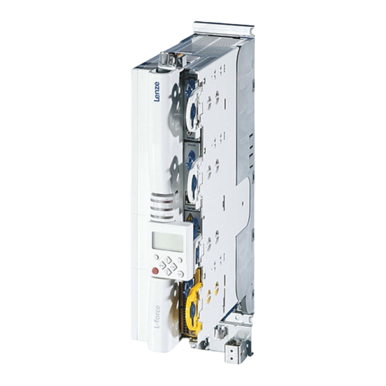
E94ASHExxxx Single Drive HighLine
E94AMHExxxx Multi Drive HighLine
Achsmodul
Axis module
Module d'axe
Módulo de eje
Modulo asse
Inbetriebnahme−Leitfaden
Commissioning guide
Guide de mise en service
Guía para la puesta en marcha
Guida per la messa in servizio
l
Werbung
Kapitel
Inhaltsverzeichnis

Verwandte Anleitungen für Lenze L-force E94ASHE Single Drive HighLine Serie


Inhaltszusammenfassung für Lenze L-force E94ASHE Single Drive HighLine Serie
- Seite 1 EDB94Axx6954 L−force Drives .Atd Inbetriebnahme−Leitfaden Commissioning guide Guide de mise en service Guía para la puesta en marcha Guida per la messa in servizio 9400 1.5 ... 695 A E94ASHExxxx Single Drive HighLine E94AMHExxxx Multi Drive HighLine Achsmodul Axis module Module d’axe Módulo de eje Modulo asse...
-
Seite 2: Überblick Technische Dokumentation Für Servo Drives 9400
MA zum Erweiterungsmodul SW Softwarehandbuch MA zum Sicherheitsmodul MA zum Zubehör MA zu Fernwartungskomponenten Parametrieren & Konfigurieren BA Keypad SW zur Lenze-Software »Engineer« SW 9400 HighLine SW zum Versorgungs-/Rückspeisemodul KHB zum Kommunikationsmodul SW zum Erweiterungsmodul SW zum Sicherheitsmodul SW zur Lenze-Technologieapplikation... -
Seite 3: Inhaltsverzeichnis
9400 HighLine | Inbetriebnahme-Leitfaden Inhalt Inhalt Über diese Dokumentation............Verwendete Konventionen . -
Seite 4: Über Diese Dokumentation
Dezimaltrennzeichen Punkt Es wird generell der Dezimalpunkt verwendet. Zum Beispiel: 1234.56 Textauszeichnung Programmname » « Die Lenze PC-Software »Engineer«... Fensterbereich kursiv Das Meldungsfenster... / Das Dialogfeld Optionen... Steuerelement fett Die Schaltfläche OK... / Der Befehl Kopieren... / Die Registerkarte Eigenschaften... -
Seite 5: Über Diese Dokumentation Definition Der Verwendeten Hinweise
9400 HighLine | Inbetriebnahme-Leitfaden Über diese Dokumentation Definition der verwendeten Hinweise Definition der verwendeten Hinweise Um auf Gefahren und wichtige Informationen hinzuweisen, werden in diesem Handbuch folgende Signalwörter und Symbole verwendet: Sicherheitshinweise Aufbau der Sicherheitshinweise: Gefahr! (kennzeichnet die Art und die Schwere der Gefahr) Hinweistext (beschreibt die Gefahr und gibt Hinweise, wie sie vermieden werden kann) Piktogramm... -
Seite 6: Sicherheitshinweise
Personen oder Sachschäden zur Folge haben können. Zum Schutz vor diesen Gefahren müssen vor dem Einschalten des Antriebsreg- lers die allgemeinen Sicherheits- und Anwendungshinweise für Lenze-Antriebs- regler in der Montageanleitung beachtet werden! Beachten Sie für die Inbetriebnahme außerdem die folgenden Hinweise! Personenschutz ... - Seite 7 9400 HighLine | Inbetriebnahme-Leitfaden Sicherheitshinweise Schutz der Maschine/Anlage Antriebe können gefährliche Überdrehzahlen erreichen (z. B. Einstellung hoher Aus- gangsfrequenzen bei dafür ungeeigneten Motoren und Maschinen): – Die Antriebsregler bieten keinen Schutz gegen solche Betriebsbedingungen. Setzen Sie dafür zusätzliche Komponenten ein. EDB94AXX6954 DE/EN/FR/ES/IT 4.0...
-
Seite 8: Basis-Inbetriebnahme
– Prozessor ab 1.4 GHz – mindestens 512 MB Arbeitsspeicher und 650 MB freie Festplattenkapazität – Betriebssystem Microsoft® Windows® 2000 (ab Service-Pack 2) oder Windows® XP Die Lenze PC-Software »Engineer« Eine Verbindung zum Antriebsregler – Zum Beispiel über Diagnoseschnittstelle X6/USB-Diagnoseadapter... - Seite 9 Inbetriebnahme-Schritte: »Engineer«-Parametrierdialog: Weiterführende Dokumentation: 1. »Engineer« starten. Softwarehandbuch/Online-Hilfe L-force »Engineer« 2. Im Start-Assistent die Vorgehensweise auswählen. Start-Assistent • Zum Beispiel die Option "Komponente aus Katalog wählen". 3. Dem Projekt die entsprechenden Komponenten aus dem Katalog hinzufügen: • Antriebsregler 9400 HighLine •...
-
Seite 10: Erweiterte Inbetriebnahme
Motor und Last ergeben. Diese charakterisieren das Übertragungsverhalten der gesamten Regelstrecke inkl. gewünschter Überwachungen. • Die Streckenparameter sind abhängig von der Anwendung, in der Antriebsregler und Motor eingesetzt werden. • Mit der Auswahl eines Lenze-Motors im »Engineer« werden für diesen Motor Streckenparameter für den lastfrei- en Betrieb vorgeschlagen. Parameter... - Seite 11 9400 HighLine | Inbetriebnahme-Leitfaden Erweiterte Inbetriebnahme Motor und Antriebsregler aufeinander abstimmen Schaltverhalten des Wechselrichters optimieren Hinweis! • Für Servoregelung nur erforderlich, wenn die Motorparameter von einem Motor eines Fremdherstel- lers bestimmt werden sollen! • Für sensorlose Vektorregelung und U/f-Steuerung immer erforderlich! –...
-
Seite 12: Erweiterte Inbetriebnahme Antriebsgrundfunktionen
9400 HighLine | Inbetriebnahme-Leitfaden Erweiterte Inbetriebnahme Antriebsgrundfunktionen Antriebsgrundfunktionen Normalhalt einstellen Der Normalhalt des Antriebs wird immer dann automatisch von der internen Zustandsmaschine aktiviert, wenn eine Grundfunktion deaktiviert wird und der Antrieb sich noch nicht im Stillstand befindet. Parametrierdialog (Registerkarte "Applikationsparameter"): ... - Seite 13 9400 HighLine | Inbetriebnahme-Leitfaden Erweiterte Inbetriebnahme Antriebsgrundfunktionen Handfahren Mit der Grundfunktion "Handfahren" kann der Antrieb von Hand verfahren werden, z. B. zum Reinigen oder Wech- seln des Werkzeugs. • Optional kann während des Verfahrens auf eine zweite Geschwindigkeit umgeschaltet werden. •...
- Seite 14 Insbesondere bei falsch parametrierten Öffnungs-/Schließzeiten kann es zum Durchsacken von Lasten kommen, bevor der Antriebsregler die Last übernimmt. Stop! Haltebremsen an Lenze-Motoren sind grundsätzlich nicht für Betriebsbremsungen ausgelegt. Der durch Betriebsbremsungen hervorgerufene erhöhte Verschleiß kann zur frühzeitigen Zerstörung der Motorhal- tebremse führen! Parametrierdialog (Registerkarte "Applikationsparameter"): ...
-
Seite 15: Klemmenbelegung Der Technologieapplikationen
9400 HighLine | Inbetriebnahme-Leitfaden Klemmenbelegung der Technologieapplikationen Stellantrieb – Drehzahl Klemmenbelegung der Technologieapplikationen Stellantrieb – Drehzahl Klemme Belegung (Lenze-Einstellung) AI1- Drehzahlsollwert AI1+ • ±10 V ≡ ±100 % Bezugsdrehzahl Motor (C00011) Reglerfreigabe Schnellhalt Drehzahlfolger freigeben Drehzahlsollwert invertieren Festsollwert 1 als Drehzahlsollwert aktivieren Fehler zurücksetzen... -
Seite 16: Klemmenbelegung Der Technologieapplikationen Positionier-Ablaufsteuerung/Tabellenpositionierung
9400 HighLine | Inbetriebnahme-Leitfaden Klemmenbelegung der Technologieapplikationen Positionier-Ablaufsteuerung/Tabellenpositionierung Positionier-Ablaufsteuerung/Tabellenpositionierung Klemme Signal (Lenze-Einstellung) AI1-/+ Vorgabe für Geschwindigkeits-Override AI2-/+ Vorgabe für Beschleunigungs-Override Schnellhalt Anschluss Referenzschalter/Touch-Probe-Sensor Anschluss Fahrbereichsendschalter für Grundfunktion "Begrenzer". • DI3 = Fahrbereichsendschalter positiv, DI4 = Fahrbereichsendschalter negativ. • Die Eingänge reagieren auf den Zustand FALSE (drahtbruchsicher). -
Seite 17: Klemmenbelegung Der Technologieapplikationen Geräteprofil Cia402 (Ab Softwarestand V7)
9400 HighLine | Inbetriebnahme-Leitfaden Klemmenbelegung der Technologieapplikationen Geräteprofil CiA402 (ab Softwarestand V7) Geräteprofil CiA402 (ab Softwarestand V7) Klemme Belegung (Lenze-Einstellung) AI1-/+ Zur freien Verfügung AI2-/+ Ansteuerung der Bremse (über Schütz) Kein Signal zugeordnet Kein Signal zugeordnet Kein Signal zugeordnet Reglerfreigabe... -
Seite 18: Hinweise Für Bestimmte Anwendungen
Während des Fangvorgangs wird der Stromregler aktiviert. Der Stromregler muss des- halb auch bei den geberlosen Betriebsarten an den Motor angepasst werden, wie in den folgenden Abschnitten beschrieben. Anpassung des Stromreglers an einen Lenze-Motor: 1. Motor im »Engineer« auswählen. 2. Schaltverhalten des Wechselrichters optimieren. - Seite 19 9400 HighLine | Inbetriebnahme-Leitfaden Hinweise für bestimmte Anwendungen Lüfter bei sensorlosen Betriebsarten Anpassung des Stromreglers an einen Motor eines Fremdherstellers: 1. Motortypenschilddaten eingeben. 2. Schaltverhalten des Wechselrichters optimieren. 3. Motorparameter bestimmen. 4. Stromregler optimieren (z. B. mit Hilfe der Oszilloskop-Funktion im »Engineer«). 5.
-
Seite 20: Diagnose
9400 HighLine | Inbetriebnahme-Leitfaden Diagnose Diagnose Hinweise zu einigen Betriebszuständen erhalten Sie schnell über die LED-Anzeige: CAN-RUN CAN-ERR DRIVE READY DRIVE ERROR 24 V USER [7-1] LED-Anzeige auf der Frontseite des Antriebsreglers Beschriftung Farbe Beschreibung CAN-RUN grün CAN-BUS o.k. CAN-ERR CAN-BUS-Fehler DRIVE READY grün... -
Seite 21: Fehlermeldung Zurücksetzen
9400 HighLine | Inbetriebnahme-Leitfaden Diagnose Antriebsdiagnose mit dem »Engineer« Registerkarte Diagnose Registerkarte Alle Parameter Kategorie "Diagnose" Reaktion auf Fehler Je nach eingestellter Reaktion auf einen Fehler wechselt die interne Gerätesteuerung ihren Zustand, setzt die Reglersperre und schaltet die LED "DRIVE ERROR" an: Reaktion Logbucheintrag Anzeige in... - Seite 108 © 02/2010 Lenze Automation GmbH Service Lenze Service GmbH Hans−Lenze−Str. 1 Breslauer Straße 3 D−31855 Aerzen D−32699 Extertal Germany Germany +49 (0)51 54 / 82−0 00 80 00 / 24 4 68 77 (24 h helpline) Ê Ê +49 (0)51 54 / 82 − 28 00 +49 (0)51 54 / 82−11 12...