Emerson FSE-0 Betriebsanleitung
Steuerteil für drehzahlregler
Verfügbare Sprachen
Verfügbare Sprachen
Quicklinks
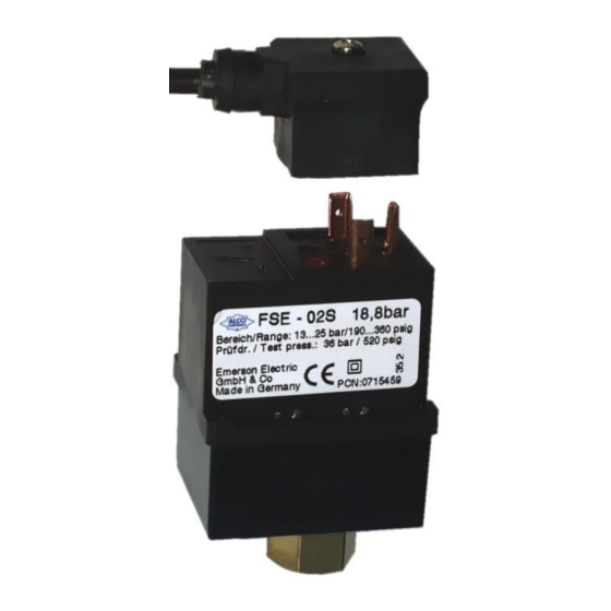
FSE Control Modules operate together with FSP
Power Modules to control the speed of condenser
fan motors according to pressure changes. Make
sure that the motor is approved by the motor/unit
manufacturer for variable speed by means of phase
cutting (TRIAC).
!
Safety instructions:
• Read
installation
instructions
Failure to comply may result in device failure,
system damage or personal injury.
• It is intended for use by persons having the
appropriate knowledge and skill.
• Before opening any system make sure pressure
in system is brought to and remains at
atmospheric pressure.
• FSE are factory set to a specific cut-off
pressure. If adjustment is needed, refer to
instructions for proper procedure. Improper
adjustment may result in system damage or
failure.
• Do not exceed safe working pressure.
• FSE are for use with FSP only. Do not connect
to any other voltage supply.
Mounting location:
see Fig. 1: after condenser (1) before accumulator
(2), preferred with pressure connection down. (3) =
fan, (4) = evaporator, (5) = mains power supply
Pressure connection:
See Fig. 2 for thread connection. Use copper gasket
(1).
See Fig. 3 for solder connection. Use damp cloth (2)
to keep housing temp. below 70°C while soldering.
Electrical connection
Use FSE-Nxx cable assembly (DIN 43650). Push
plug slightly on the pins of control module. Only
one direction possible see Fig. 4. No gasket required.
Fasten screw with 0,05 Nm.
Note: Plug can not be repaired. In case of failure
replace connector.
FSE__65094__R05.doc
Operating Instructions
Control Modules FSE-0
Leakage test:
• After completion of installation, a test pressure
must be carried out as follows:
- According to EN378 for systems which must
comply
with
directive 97/23/EC
- To maximum working pressure of system for other
applications
thoroughly.
Warning:
1. Failure to do so may result in loss of refrigerant
and person injury.
2. The pressure test must be conducted by skilled
persons with due respect regarding the danger
related to pressure.
Setting
FSE-0 Control Modules are factory preset for 2V
output voltage if decreasing pressure / temperature
falls below the value given in the table below.
Factory Set Point
Type
Refrigerant
FSE-01_ R134a
FSE-02_ R22
FSE-02_ R407C
FSE-02_ R507
FSE-03_ R410A
For temperatures below these values FSP will stop
fan motors (cut-off).
For adjustment to other settings follow procedure
below before mounting FSE (Numbers refer to Fig.
5):
Remove sealing cap (3). Insert enclosed 2mm allen
key (2) into adjustment screw (1). Turn allen key
clockwise (+) to increase, or counterclockwise (-) to
decrease pressure setting. Do not turn adjustment
screw more than 3 turns clockwise (+3).
1 turn causes a pressure change of approximately 2.6
bar.
Replacement for 04
Emerson Electric GmbH & Co. OHG
GB
Heerstr.111 – D-71332 Waiblingen
Tel.: 07151 509-0 - Fax.: -200
European
pressure
equipment
Pressure bar
Temp. °C
7.8
35
15.5
43
15.5
37.5
15.5
36.5
20.4
35
Date: 23.07.2009
www.emersonclimate.eu
To readjust to factory setting, a pressure gauge, a
constant voltage of 10 VDC and a DC volt meter is
needed. Apply constant voltage between pin 2 (+)
and pin 4 (-). Connect voltage meter between pin 1
(+) and pin 4 (-). Apply pressure of
maximum operating pressure PS, than decrease
pressure slowly to the needed setpoint per table
"Factory Set Point". Pressure should not be below
setpoint at any time. Adjust voltage with adjustment
screw (1) to 2 V. For confirmation decrease pressure
to ~30% of maximum pressure PS, than increase to
~60% of PS, than decrease again slowly to setpoint.
If necessary correct again with adjustment screw (1).
After adjustment insert sealing cap (3) and make
sure that it is properly fitted. IP65 protection
requires firmly sealed plug.
Technical Data
Supply voltage:
Output signal:
Max. medium temperature at
pressure connection:
Ambient temperature range TS:
Max. operating
Pressure PS
FSE-01_:
27 bar
FSE-02_:
32 bar
FSE-03_:
43 bar
Medium
HFC, HCFC
compatibility:
Protection class:
IP 65 according to EN
60529/IEC 529
Marking:
~60% of
10 VDC
0 ... 10 V
70°C
-20°C ... +65°C
Test Pressure
PT
30 bar
36 bar
48 bar
PCN: 0716136

Verwandte Anleitungen für Emerson FSE-0


Inhaltszusammenfassung für Emerson FSE-0
- Seite 2 Einstellung genau nach dieser Anweisung Einstellung: Nach Einstellarbeiten Dichtungskappe (3) wieder verfahren. Eine unsachgemäße Einstellung Die FSE-0 Steuerteile sind ab Werk folgendermaßen einsetzen. Schutzart IP65 wird nur mit fest kann zum Ausfall von Anlagenteilen führen. eingestellt: Das Ausgangssignal von 2 V wird geschlossener Dichtungskappe erreicht.