GEO416 - GEO416GS 1. SAFETY PRECAUTIONS AND PROCEDURES The instrument was designed in compliance with standards IEC/EN61557 and IEC/EN61010-1 relative to electronic equipment. CAUTION For your own safety and to avoid damaging the instrument you are recommended to follow the procedures described in this manual and read...
GEO416 - GEO416GS 1.2. DURING USE You are recommended to read carefully the following instructions: CAUTION Failure to comply with warnings and instructions may damage the instrument and/or its components as well as injure the operator. If the low battery symbol is displayed during use interrupt testing and replace batteries following the procedure described in §...
GEO416 - GEO416GS 2. GENERAL DESCRIPTION This instrument will grant you accurate and reliable measurements provided that is used according to the instructions given in this manual. You will enjoy the highest safety thanks to a development of newest conception assuring double insulation and over voltage category III.
GEO416 - GEO416GS 4.2.1. Switching on When switching on the instrument a brief tone is audible along with display of all segments for about one second. Subsequently the last firmware version as well as the last selected measuring mode are displayed before switching off.
GEO416 - GEO416GS 4.3. EARTH 3W – 3 WIRE EARTH RESISTANCE MEASUREMENT The measurement is carried out in compliance with standards IEC 781, VDE 0413, IEC/EN61557-5. CAUTION The instrument can be used for voltage and current measurements on installations with over voltage category CAT III 240V to earth and maximum voltage of 415V between inputs.
Seite 9
GEO416 - GEO416GS Extend, if necessary, the blue and red measuring cables separately using cables with proper section. Adding any extension does not require calibration and does not affect the measured earth resistance value Drive the auxiliary rods into the ground keeping to the distance instructions provided by the standards (§...
GEO416 - GEO416GS 4.4. EARTH 2W – 2 WIRE EARTH RESISTANCE MEASUREMENT CAUTION The instrument can be used for voltage and current measurements on installations with over voltage category equal to CAT III 240V to earth and maximum voltage of 415V between inputs. Do not connect the instrument to installations whose voltages exceed the limits indicated in this manual.
Seite 11
GEO416 - GEO416GS CAUTION If you wish to effect the measurement using the neutral and earth conductors of an ordinary socket, you may accidentally connect to phase; in this case the detected voltage as well as the warning symbol for wrong entering will be...
Seite 12
GEO416 - GEO416GS While the instrument is measuring a screen similar to the one beside appears where the instrument’s input interfering voltage value is displayed. When the message is displayed Input interfering voltage do not disconnect or touch the test...
GEO416 - GEO416GS 4.5. - GROUND RESISTIVITY MEASUREMENT The ground resistivity value is an essential parameter to calculate the resistance value of the earth rods to be used for the earth installation’s construction. The measurement is effected according to standards IEC 781, VDE 0413, IEC/EN61557-5.
Seite 14
GEO416 - GEO416GS A screen similar to the one beside appears where both the input interfering voltage of the instrument and the rods’ distance value are displayed Value of input interfering voltage and rods' distance Should you need to modify the rods’...
Seite 15
GEO416 - GEO416GS 11. While the instrument is measuring a screen similar to the one beside appears where the instrument’s input interfering voltage value distance set between auxiliary rods are displayed. When the message Value of input interfering voltage and rods' distance...
GEO416 - GEO416GS 4.5.1. Anomalous measuring applications When starting a measurement the instrument checks the continuity of Volt circuit’s resistance too high measuring cables. If the volt circuit (red cable S and green cable ES) is interrupted or its resistance value is...
Seite 17
GEO416 - GEO416GS When starting a measurement, if the red cable (connected to S terminal) and the green cable (connected to ES terminal) are reversed, the instrument do not perform the test, emits a long green cables reversed sound tone and displays the screen beside Example under ρ...
GEO416 - GEO416GS 5. MANAGEMENT OF STORED DATA 5.1. HOW TO SAVE A MEASUREMENT After taking a measurement No. of memory location press SAVE key, the instrument where the measurement displays a screen similar to the has to be saved...
GEO416 - GEO416GS Press key, instrument displays a screen similar to the one beside First last memory location to be cancelled and confirmation required Alternatively: Confirm cancellation of measurements pressing ENTER key, the instrument emits a double sound tone confirming cancellation of the...
GEO416 - GEO416GS 6. INSTRUMENT RESET CAUTION BEFORE CARRYING OUT THE INSTRUMENT’S RESET SAVE ALL DATA RELATIVE TO THE MEASUREMENTS EFFECTED BY DOWNLOADING THEM TO A PC When the instrument is off press the RCL/CLR key Keeping down the RCL/CLR key, press the switch on key.
GEO416 - GEO416GS 8. MAINTENANCE 8.1. GENERAL This is a precision instrument. Strictly follow the instructions for use and storage reported in this manual to avoid any possible damage or danger during use. Do not use this tester under unfavorable conditions of high temperature or humidity. Do not expose to direct sunlight.
This instrument complies with the requirements of the European Low Voltage Directive 2006/95/CE (LVD) and EMC Directive 2004/108/CE 9.3. ACCESSORIES 9.3.1. Standard and optional accessories GEO416 See enclosed packing list 9.3.2. Standard accessories GEO416GS Set of 4 cables, banana-banana, L=1m KIT416CV ...
GEO416 - GEO416GS SERVICE 10.1. WARRANTY TERMS This instrument is guaranteed against material or manufacturing defects, in accordance with general sales conditions. During the warranty period the manufacturer reserves the right to decide either to repair or replace the product.
GEO416 - GEO416GS PRACTICAL REPORTS FOR ELECTRICAL TESTS 11.1. EARTH RESISTANCE IN TT SYSTEMS The test is aimed at checking that the RCD is coordinated with the earth resistance value. It is not possible to assume an earth resistance value as reference limit when controlling the test result, while it is necessary to check every time that the co-ordination complies with the requirements of the Standards.
GEO416 - GEO416GS 11.2. EARTH RESISTANCE, VOLTAAMPEREMETRIC METHOD 11.2.1. Creating cables extensions If the length of the supplied cables isn’t suitable for the plant under test, You can create your own extensions without influencing the instrument’s accuracy. For your own safety and to avoid damaging the instrument you are recommended to respect the following indications: ...
GEO416 - GEO416GS Fig. 8: Earth resistance measurement – large-sized earth rods 11.3. GROUND RESISTIVITY This test aims at analyzing the resistivity value of the ground in order to define the type of rods to be used when designing the installation. For the resistivity test correct or not correct values do not exist.
GEO416 - GEO416GS The measuring method allows defining the specific resistivity of a ground layer up to the depth corresponding approximately to the distance “a” between the rods. If you increase the distance “a” you can reach deeper ground layers and check the ground homogeneity.
Seite 29
ESPAÑOL Manual de instrucciones Copyright HT ITALIA 2012 Versión ES .0 - 4/ /2012...
Seite 30
Ambiente ......................... 22 9.2.1. Condiciones ambientales de uso ................... 22 9.3. Accesorios ........................22 9.3.1. Accesorios en dotación y opcionales GEO416 ..............22 9.3.2. Accesorios en dotación GEO416GS ..................22 ASISTENCIA ......................23 ...
GEO416 - GEO416GS 1. PRECAUCIONES Y MEDIDAS DE SEGURIDAD El instrumento ha sido proyectado conforme a las directivas IEC/EN61557-1 y IEC/EN 61010-1 relativas a los instrumentos de medida electrónicos. ATENCIÓN Para su seguridad y para evitar dañar el instrumento, le rogamos que siga los procedimientos descritos en el presente manual y lea con particular atención...
GEO416 - GEO416GS 1.2. DURANTE EL USO Le rogamos que lea atentamente las recomendaciones y las instrucciones siguientes: ATENCIÓN La falta de observación de las Advertencias y/o Instrucciones pueden dañar el instrumento y/o sus componentes o ser fuente de peligro para el usuario. Si durante el uso aparece el símbolo de pila agotada, suspenda la prueba y...
GEO416 - GEO416GS 2. DESCRIPCIÓN GENERAL El instrumento está realizado de modo que garantiza la máxima seguridad gracias a un desarrollo de nueva concepción que asegura el doble aislamiento y el cumplimiento de la categoría de sobretensión III. 2.1. FUNCIONALIDAD DEL INSTRUMENTO ...
GEO416 - GEO416GS 4.2.1. Encendido Al encender el instrumento emite una breve señal acústica y durante un segundo se visualizan todos los segmentos del visualizador. Sucesivamente muestra la versión del firmware cargada, luego aparece la última modalidad de medición seleccionada antes del apagado.
GEO416 - GEO416GS 4.3. EARTH 3W – MEDICIÓN DE LA RESISTENCIA DE TIERRA A 3 PUNTOS La medida será efectuada en acuerdo con la normativa UNE 20460, IEC 781, VDE 0413, IEC/EN61557-5 ATENCIÓN El instrumento puede ser utilizado sobre instalaciones con categoría de sobretensión CAT III 240V respecto tierra con tensiones máximas de 415V...
Seite 37
GEO416 - GEO416GS Prolongue, si fuese necesario, los cables de medida azul y rojo separadamente utilizando cables de sección adecuada. La presencia de eventuales prolongaciones no requiere calibración y no modifica el valor de la resistencia de tierra medida Clave en el terreno los dispersores auxiliares según la distancia prevista por la norma (§...
GEO416 - GEO416GS 4.4. EARTH 2W – MEDICIÓN DE LA RESISTENCIA DE TIERRA A 2 PUNTOS ATENCIÓN El instrumento puede ser utilizado sobre instalaciones con categoría de sobretensión CAT III 240V respecto tierra con tensiones máximas de 415V entre las entradas. No conecte el instrumento a una instalación con tensiones que excedan los límites indicados en este manual.
Seite 39
GEO416 - GEO416GS ATENCIÓN Si se desea efectuar la medida utilizando el conductor de neutro y de tierra de una toma de corriente, evite conectar accidentalmente sobre la fase; en cuyo caso el visualizador indicará la tensión detectada, aparecerá el símbolo de ATENCIÓN...
Seite 40
GEO416 - GEO416GS Mientras el instrumento efectua la medición será visualizada una ventana como la muestra donde será mostrado el valor de la tensión de dispersión en la entrada del instrumento. Mientras sobre Valor de la tensión de el visualizador del instrumento aparece dispersión en la entrada...
GEO416 - GEO416GS - MEDICIÓN DE LA RESISTIVIDAD DEL TERRENO 4.5. El valor de la resistividad del terreno es un parámetro indispensable para calcular el valor de la resistencia de los dispersores que se van a utilizar para la realización de una instalación de tierra.
Seite 42
GEO416 - GEO416GS Sobre visualizador aparece siguiente pantalla donde nos muestra el valor de la tensión de dispersión en las entradas del instrumento y el valor de la distancia entre dispersores seleccionados Valor de la tensión de dispersión en las entradas...
Seite 43
GEO416 - GEO416GS 11. Mientras el instrumento efectua la medición será visualizada una ventana como la muestra donde será mostrado el valor de la tensión de dispersión en la entrada del instrumento. Mientras sobre Valor de la tensión de el visualizador del instrumento aparece dispersión en las entradas...
GEO416 - GEO416GS 4.5.1. Situaciones anómalas en mediciones Al inicio de la medición el instrumento verifica la continuidad de los cables de Resistencia circuito voltimétrico muy elevada medida. Cuando circuito voltimétrico (cable rojo S y verde ES) esté interrumpido o presente una Valor de la tensión de...
Seite 45
GEO416 - GEO416GS Al inicio de la medición, cuando los cables rojo (conectado al terminal S) y verde (conectado al terminal ES) estén invertidos entre ellos, instrumento no efectua la prueba, emite señal acústica prolongada Cable rojo verde invertidos entre ellos visualizará...
GEO416 - GEO416GS 5. GESTIÓN DE LOS DATOS EN MEMORIA 5.1. COMO GUARDAR UNA MEDIDA Después de haber efectuado Número de la localización una medición pulse la tecla de memoria en la cual SAVE, el instrumento visualiza será memorizada medida la siguiente pantalla Útimo valor guardado del...
GEO416 - GEO416GS Pulse tecla CLR, instrumento visualiza siguiente pantalla Primera última localización de memoria cancelada y confirmada En alternativa: Confirmar la cancelación de las medidas pulsando la tecla ENTER, el instrumento emite una doble señal acústica indicando la cancelación...
GEO416 - GEO416GS 6. RESET DEL INSTRUMENTO ATENCIÓN ANTES DE EJECUTAR EL RESET AL INSTRUMENTO GUARDE LOS DATOS RELATIVOS MEDIDAS EFECTUADAS TRANSFIRIENDOLAS A UN PC Antes de encender el instrumento pulse la tecla RCL/CLR Mantenga pulsada la tecla RCL/CLR, pulse la tecla de encendido.
GEO416 - GEO416GS 8. MANTENIMIENTO 8.1. GENERALIDADES El instrumento que Usted ha adquirido es un instrumento de precisión. Durante el uso y el almacenamiento respete las recomendaciones enumeradas en este manual para evitar posibles daños o peligros durante el uso.
GEO416 - GEO416GS 9. ESPECIFICACIONES TÉCNICAS 9.1. CARACTERÍSTICAS TÉCNICAS Incertidumbre indicada es [%lectura + (número digs*resolución)] a 23°C±5°C, < 80%HR Mediciones de la resistencia de tierra a 3 y a 2 puntos - EARTH 3W y EARTH 2W Escala (**) Resolución []...
Este instrumento es conforme a los requisitos de la Directiva Europea sobre baja tensión 2006/95/CE (LVD) y de la directiva EMC 2004/108/CE 9.3. ACCESORIOS 9.3.1. Accesorios en dotación y opcionales GEO416 Ver lista adjunta 9.3.2. Accesorios en dotación GEO416GS Conjunto 4 cables banana-banana L=1m KIT416CV ...
GEO416 - GEO416GS ASISTENCIA 10.1. CONDICIONES DE GARANTIA Este instrumento está garantizado contra cada defecto de materiales y fabricaciones, conforme con las condiciones generales de venta. Durante el período de garantía, las partes defectuosas pueden ser sustituidas, pero el fabricante se reserva el derecho de repararlo o bien sustituir el producto.
GEO416 - GEO416GS FICHAS PRÁCTICAS PARA LAS VERIFICACIONES ELÉCTRICAS 11.1. MEDIDAS DE LA RESISTENCIA DE TIERRA EN LOS SISTEMAS TT Verificar que el dispositivo de protección sea coordinado con el valor de la resistencia de tierra. No se puede asumir a priori un valor de resistencia de tierra límite de referencia al que hacer referencia en el control del resultado de la medida, pero es necesario en su momento controlar que sea respetado la coordinación prevista por la normativa.
GEO416 - GEO416GS 11.2. RESISTENCIA TIERRA MÉTODO VOLTIAMPERIMÉTRICO 11.2.1. Autoconstrucción del prologador En el caso que la longitud de los cables incluidos en dotación con el instrumento no es suficiente, es posible realizar un prolongador para efectuar la medida en la instalación en examen sin despreciar la precisión del mismo instrumento.
GEO416 - GEO416GS Fig. 8: Medición de la resistencia de tierra - anillos de grandes dimensiones 11.3. RESISTIVIDAD DEL TERRENO La misión de la prueba es analizar el valor de la resistividad del terreno para definir, en fase de proyectación, la tipologia de los dispersores de tierra a utilizar en una instalación.
GEO416 - GEO416GS El método de medida permite de obtener la resistividad especifica hasta la profundidad correspondiente aproximadamente de la distancia “a“ entre dos dispersores auxiliares. Usted si aumenta “a “puede obtener lecturas a más profundidad de terreno, por tanto es posible controlar la homogeneidad del terreno.
Seite 57
DEUTSCH Bedienungsanleitung Copyright HT ITALIA 2012 Ausführung DE .0 - 4/ /2012...
Seite 58
9.2. Umgebungsbedingungen ....................22 9.2.1. Umgebungsbedingungen für den Betrieb ................22 9.3. Zubehörteile ........................22 9.3.1. Standard und Optionales Zubehör GEO416 ................22 9.3.2. Standard Zubehör GEO416GS ....................22 SERVICE ........................23 ...
GEO416 - GEO416GS 1. SICHERHEITSHINWEISE UND ARBEITSVORSCHRIFTEN Das Gerät wurde in Übereinstimmung mit den Normen IEC/EN61557 und IEC/EN61010-1 für elektronische Geräten entwickelt. VORSICHT Zu Ihrer eigenen Sicherheit und zur Vermeidung von Beschädigungen des Geräts wird empfohlen, diesem Handbuch beschriebenen Arbeitsvorschriften zu befolgen und alle Anweisungen sorgfältig zu lesen, denen dieses Symbol voBereichstellt ist: Vor und während den Messungen müssen die folgenden Anweisungen befolgt werden:...
GEO416 - GEO416GS 1.2. WÄHREND DER VERWENDUNG Es wird empfohlen, die folgenden Anweisungen sorgfältig zu lesen: VORSICHT Werden die Warnhinweise und Anweisungen nicht befolgt, kann dies zu Schäden am Gerät und/oder seinen Komponenten sowie zu Verletzungen des Benutzers führen Wenn das Symbol für niedrige Batteriespannung während der Verwendung angezeigt wird, unterbrechen Sie die Messung und setzen Sie neue Batterien ein, wie in §...
GEO416 - GEO416GS 2. ALLGEMEINE BESCHREIBUNG Dieses Gerät bietet Ihnen genaue und verlässliche Messungen unter der Voraussetzung, das es gemäß den in diesem Handbuch gegebenen Anweisungen betrieben wird. Es bietet höchste Sicherheit, da es konzeptuell neu entwickelt ist, doppelte Isolierung bietet und zur Überspannungskategorie III gehört.
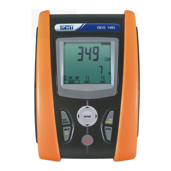
GEO416 - GEO416GS 4. ARBEITSANWEISUNGEN 4.1. BESCHREIBUNG DES GERÄTS LEGENDE: 1. Eingänge 2. ENTER/,,, Taste 3. ESC/ Taste 4. RCL/CLR-Taste 5. Anzeige 6. GO-Taste 7. SAVE-Taste 8. ON/OFF-Taste Abb. 1: Beschreibung des Geräts ENTER-Taste zur Auswahl des Messmodus Pfeiltasten zum Bewegen des Cursors bei der Auswahl erforderlicher Parameter -Taste zum Einschalten der Anzeige-Hintergrundbeleuchtung für 30...
GEO416 - GEO416GS 4.2.1. Einschalten Beim Einschalten des Geräts ist ein kurzer Ton zu hören; dazu werden alle Segmente der Anzeige kurz aktiviert. Danach werden die neueste Firmware-Version sowie der vor dem Abschalten zuletzt gewählte Messmodus angezeigt. 4.2.2. Automatische Abschaltung Das Gerät schaltet sich 3 Minuten, nachdem zuletzt eine Taste gedrückt wurde,...
GEO416 - GEO416GS 4.3. EARTH 3W – ERDUNGSWIDERSTANDSMESSUNG (3 PUNKT) Die Messung wird in Übereinstimmung mit den Normen IEC 781, VDE 0413, EN61557-5 durchgeführt. VORSICHT Das Gerät kann für Spannungs- und Stromstärkemessungen an Anlagen mit Überspannungskategorie III von 240 V an Erde und von maximal 415 V zwischen den Eingängen verwendet werden.
Seite 65
GEO416 - GEO416GS Falls nötig, das blaue und das rote Messkabel separat mit Kabeln mit geeignetem Querschnitt verlängern. Das Hinzufügen jeglicher Verlängerungen erfordert keine Kalibrierung und beeinträchtigt die Messung des Erdungswiderstandswerts nicht Stecken Sie die Erdspieße in die Erde und halten Sie die in den Normen (§ 11.2) angegebenen Abstände ein...
GEO416 - GEO416GS 4.4. EARTH 2W – ERDUNGSWIDERSTANDSMESSUNG MIT ZWEI KABELN VORSICHT Das Gerät kann für Spannungs- und Stromstärkemessungen an Anlagen mit Überspannungskategorie III von 240 V an Erde und von maximal 415 V zwischen den Eingängen verwendet werden. Das Gerät darf nicht an Installationen angeschlossen werden, deren Spannungen die in diesem Handbuch genannten Grenzwerte übersteigen.
Seite 67
GEO416 - GEO416GS VORSICHT Wenn Sie die Messung mit den Neutral- und Erdleitern einer gewöhnlichen Steckdose durchführen möchten, könnten Sie das Gerät versehentlich an Phase anschließen; in diesem Fall wird die gemessene Spannung und das Warnsymbol für falsche Eingabe angezeigt und es wird keine Messung durchgeführt, selbst wenn die Taste GO gedrückt wird...
Seite 68
GEO416 - GEO416GS Während das Gerät misst, wird ein Bildschirm nebenstehende angezeigt, in dem das Gerät die Eingangsstörspannung anzeigt. Wenn die Meldung angezeigt wird, die Wert der Messkabel nicht abklemmen oder Eingangsstörspannung berühren VORSICHT Wird die Messung gestartet, wird die Eingangsstörspannung sowohl am Volt- als auch am Ampere-Kreis gemessen.
GEO416 - GEO416GS 4.5. - MESSUNG DES SPEZIFISCHEN ERWIDERSTANDES Der spezifische Erdwiderstand ist ein wesentlicher Parameter zur Berechnung des Widerstandswerts von Erdspießen, die in der Konstruktion einer Erdinstallation verwendet werden. Die Messung wird entsprechend den Normen IEC 781, VDE 0413 IEC/EN61557- 5 durchgeführt.
Seite 70
GEO416 - GEO416GS wird Bildschirm nebenstehende angezeigt, sowohl die Eingangsstörspannung des Geräts wie auch die Abstände der Wert der Eingangsstör- spannung der eingestellter Spieße angezeigt werden Abstand der Spieße Wenn Sie den Abstand der Spieße ändern möchten, Wert für den Abstand der drücken Sie die Pfeiltasten ,...
Seite 71
GEO416 - GEO416GS 11. Während das Gerät misst, wird ein Bildschirm nebenstehende angezeigt, in dem das Gerät die Eingangsstörspannung eingestellten Abstand zwischen den Erdspießen anzeigt. Wenn die Meldung Wert der Eingangsstör- spannung der eingestellter angezeigt wird, die Messkabel Abstand der Spieße nicht abklemmen oder berühren...
GEO416 - GEO416GS 4.5.1. Anormale Messanwendungen Beim Starten der Messung prüft das Gerät den Durchgang aller Messkabel. Widerstand des Volt- Kreises ist zu hoch Wenn der Volt-Kreis (rotes Kabel S und grünes Kabel ES) unterbrochen ist oder sein Widerstandswert zu hoch ist, zeigt Wert der Eingangsstör-...
Seite 73
GEO416 - GEO416GS Wenn die Messung gestartet wird, wenn das rote Kabel (das an Anschluss S angeschlossen ist) und das grüne Kabel (das an Anschluss ES angeschlossen ist) miteinander vertauscht sind, führt Rote und grüne Kabel vertauscht das Gerät die Messung nicht durch.
GEO416 - GEO416GS 5. VERWALTUNG GESPEICHERTER DATEN 5.1. WIE EINE MESSUNG GESPEICHERT WIRD Nach der Durchführung einer Nr. des Speicherorts, in Messung drücken Sie die Taste den die Messung SAVE. Das Gerät zeigt nun gespeichert werden soll einen Bildschirm Zuletzt eingestellter Wert nebenstehenden an für die Parameter L und P...
GEO416 - GEO416GS Drücken Sie die CLR-Taste. Das Gerät zeigt nun einen Bildschirm Der erste und der letzte zu nebenstehenden an löschende Speicherort; Bestätigung erforderlich Alternativ: Bestätigen Sie das Löschen von Messungen durch Drücken der Taste ENTER. Das Gerät bestätigt das Löschen der gewählten...
GEO416 - GEO416GS 6. GERÄT ZURÜCKSETZEN (HARD RESET) VORSICHT VOR DEM ZURÜCKSETZEN DES GERÄTS SOLLTEN ALLE ZUR MESSUNG GEHÖRENDEN DATEN GESPEICHERT WERDEN. LADEN SIE DIE DATEN HIERZU AUF EINEN PC Wenn das Gerät abgeschaltet ist, drücken Sie die Taste RCL/CLR Halten Sie die Taste RCL/CLR gedrückt und...
GEO416 - GEO416GS 8. INSTANDHALTUNG 8.1. ALLGEMEIN Dies ist ein Präzisionsinstrument. Halten Sie sich strikt an die Anweisungen zur Verwendung und Lagerung wie in diesem Handbuch beschrieben, um jegliche Beschädigungen oder Gefahren bei der Verwendung zu vermeiden. Verwenden Sie dieses Messgerät nicht unter ungeeigneten Bedingungen wie hoher Temperatur oder hoher Luftfeuchte.
GEO416 - GEO416GS 9. TECHNISCHE DATEN 9.1. TECHNISCHE MERKMALE Ungenauigkeit ist angegeben als [%Anzeige + (Ziffer*Auflösung)] bei 23°C±5°C, < 80%HR Erdungswiderstandsmessung mit 3 Punkt und 2 Punkt ( EARTH 3W und EARTH 2W) Bereich (**) Auflösung [] Ungenauigkeit (*) Ablesung [] Messung []...
Dieses Gerät erfüllt die Anforderungen der Europäischen Niederspannungs- Richtlinie 2006/95/CE (LVD) und der EMV-Richtlinie 2004/108/CE 9.3. ZUBEHÖRTEILE 9.3.1. Standard und Optionales Zubehör GEO416 Siehe die beiliegende Liste der Zubehörteile. 9.3.2. Standard Zubehör GEO416GS Set bestehend aus 4 Messleitungen, L = 1m KIT416CV ...
GEO416 - GEO416GS SERVICE 10.1. GARANTIEBEDINGUNGEN Dieses Gerät verfügt über eine Garantie gegen Material- oder Herstellungsfehler gemäß den allgemeinen Verkaufsbedingungen. Während der Garantiezeit behält sich der Hersteller das Recht vor, das Gerät entweder zu reparieren oder zu ersetzen. Sollten Sie das Gerät aus irgendwelchen Gründen zur Reparatur oder zwecks Austausch zurücksenden, sprechen Sie dies bitte zuvor mit Ihrem lokalen Händler ab.
GEO416 - GEO416GS PRAKTISCHE HINWEISE FÜR ELEKTRISCHE MESSUNGEN 11.1. ERDUNGSWIDERSTAND IN TT-SYSTEMEN Diese Messung zielt darauf ab, zu prüfen, ob der RCD mit dem Wert des Erdungswiderstands abgestimmt ist. Es ist nicht zulässig, einen Erdungswiderstand als Referenz-Grenzwert anzunehmen, wenn das Messergebnis kontrolliert wird. Es ist vielmehr jedes Mal notwendig, zu prüfen, ob die Abstimmung die Anforderungen der...
GEO416 - GEO416GS 11.2. ERDUNGSWIDERSTAND, VOLTAMPEREMETRISCHE METHODE 11.2.1. Messleitungen verlängern Sollten die zum Lieferumfang gehörigen Messleitungen für die Messaufgabe nicht lang genug sein, können Sie diese verlängern, ohne die Messgenauigkeit des Instrumentes zu beeinflussen. Zur eigenen Sicherheit und zur Vermeidung von Schäden am Messgerät, empfehlen wir Ihnen folgende Anweisungen zu beachten.
GEO416 - GEO416GS Abb. 8: Erdungswiderstandsmessung – groß dimensionierte Erdspieße 11.3. SPEZIFISCHER ERDWIDERSTAND Diese Messung zielt darauf ab, den Wert des spezifischen Erdwiderstand zu bestimmen, um die Art der für die Installation zu verwendenden Erdspieße festzustellen. Für die Messung des spezifischen Erdungswiderstands existieren keine richtigen oder falschen Werte.
GEO416 - GEO416GS Die Messmethode erlaubt die Bestimmung des spezifischen Erdungswiderstands einer Erdschicht bis zu der Tiefe, die etwa dem Abstand “a” zwischen den Spießen entspricht. Wenn Sie den Abstand “a” erhöhen, können Sie tiefere Bodenschichten erreichen und die Homogenität des Bodens prüfen. Nach mehreren Messungen können Sie ein Profil darüber erstellen, welche Art von Erdspieß...
Seite 85
FRANÇAIS Manuel d’utilisation Copyright HT ITALIA 2012 Version FR .0 - /2012...
GEO416 - GEO416GS 1. PRECAUTIONS ET MESURES DE SECURITE Cet instrument a été conçu conformément aux directives IEC/EN61557 et IEC/EN61010-1, relatives aux instruments de mesure électroniques. ATTENTION Pour votre propre sécurité et afin d’éviter tout endommagement de l’instrument, veuillez suivre avec précaution les instructions décrites dans ce manuel et lire attentivement toutes les remarques précédées du symbole...
GEO416 - GEO416GS 1.2. PENDANT L’UTILISATION Lire attentivement les recommandations et instructions suivantes : ATTENTION Le non-respect des avertissements et/ou instructions pourrait endommager l’instrument et/ou ses composants ou mettre en danger l’utilisateur. Si le symbole de batterie déchargée s'affiche pendant l'utilisation, suspendre les essais et remplacer les piles en suivant la procédure dont à...
GEO416 - GEO416GS 2. DESCRIPTION GENERALE L'instrument que vous venez d'acheter, si utilisé conformément à ce qui est décrit dans ce manuel, vous garantira des mesures soignées et fiables, ainsi que le maximum de sécurité, grâce à son développement de toute nouvelle conception assurant le double isolement et l'obtention de la catégorie de surtension III.
GEO416 - GEO416GS 4.2.1. Allumage Lors de l'allumage, l'instrument émet un bref signal sonore et affiche tous les segments de l'afficheur pendant une seconde environ. Il montre ensuite la version du firmware chargée et se met dans le dernier mode de mesure sélectionné avant l'extinction.
GEO416 - GEO416GS 4.3. EARTH 3W – MESURE DE LA RESISTANCE DE TERRE A 3 POINTS La mesure est exécutée conformément à la réglementation VDE 0413, IEC/EN61557-5. ATTENTION L'instrument peut être utilisé sur des installations en catégorie de surtension CAT III 240V à la terre avec une tension maximale de 415V entre les entrées.
Seite 93
GEO416 - GEO416GS Le cas échéant, rallonger les câbles de mesure bleu et rouge séparément en utilisant des câbles ayant une section appropriée. La présence de rallonges éventuelles ne demande aucune calibration ni ne modifie la valeur de résistance de terre mesurée.
GEO416 - GEO416GS 4.4. EARTH 2W – MESURE DE LA RESISTANCE DE TERRE A 2 POINTS ATTENTION L'instrument peut être utilisé sur des installations en catégorie de surtension CAT III 240V à la terre avec une tension maximale de 415V entre les entrées.
Seite 95
GEO416 - GEO416GS ATTENTION Si l'on souhaite effectuer la mesure en utilisant les conducteurs de neutre et de terre d'une prise de courant normale, il peut arriver accidentellement de se connecter à la phase ; dans ce cas-ci, l'écran montrera la tension détectée, le symbole d'attention ce qui signale une introduction erronée et il n'effectuera...
Seite 96
GEO416 - GEO416GS Pendant l'exécution de la mesure de la part de l'instrument, l'afficheur montre une page-écran comme celle ci-contre où l'on trouve la valeur de la tension de perturbation à l'entrée de l'instrument. Valeur de la tension de Pendant l'affichage du message perturbation à...
Seite 97
GEO416 - GEO416GS - MESURE DE LA RESISTIVITE DU SOL 4.5. La valeur de résistivité du sol est un paramètre indispensable pour calculer la valeur de résistance des électrodes de mise à la terre que l'on utilisera pour réaliser l'installation de terre.
Seite 98
GEO416 - GEO416GS L'afficheur montre page-écran comme celle ci-contre où l'on trouve la valeur de la tension de perturbation à l'entrée de l'instrument et la valeur de la distance sélectionnée entre Valeur de la tension de électrodes de mise à la terre.
GEO416 - GEO416GS 11. Pendant l'exécution de la mesure de la part de l'instrument, l'afficheur montre une page-écran comme celle ci-contre où l'on trouve la valeur de la tension de perturbation à l'entrée et la distance Valeur de la tension de sélectionnée entre les électrodes de...
GEO416 - GEO416GS 4.5.1. Situations d'anomalies pour les mesures démarrage mesure, l'instrument vérifie la continuité des Résistance circuit voltmétrique trop élevée câbles mesure. circuit voltmétrique (câbles rouge S et vert interrompu Valeur de la tension de résistance trop élevée, l'instrument perturbation à...
Seite 101
GEO416 - GEO416GS Au démarrage de la mesure, si les câbles rouge (connecté à la borne S) et vert (connecté à la borne ES) sont inversés entre eux, l'instrument n'exécute pas l'essai, émet un signal sonore prolongé et montre la page- Câbles...
GEO416 - GEO416GS 5. GESTION DES DONNEES EN MEMOIRE 5.1. COMMENT SAUVEGARDER UNE MESURE Après l'exécution d'une mesure, appuyer sur la touche SAVE, Numéro de l'emplacement de mémoire où la mesure l'instrument affiche une page- sera mémorisée écran comme celle ci-contre.
GEO416 - GEO416GS Appuyer sur la touche CLR, l'instrument affiche une page- écran comme celle ci-contre. Premier dernier emplacement de mémoire à effacer et demande de confirmation Autrement : Confirmer l'effacement des mesures en appuyant sur la touche ENTER, l'instrument émet un double signal sonore ce qui indique l'effacement effectué...
GEO416 - GEO416GS 6. RESET DE L'INSTRUMENT ATTENTION AVANT D'EXÉCUTER LE RESET (REMISE À ZÉRO) DE L'INSTRUMENT, SAUVEGARDER DONNÉES CONCERNANT MESURES EFFECTUÉES LES TRANSFÉRANT AU PC. L'instrument éteint, appuyer sur la touche RCL/CLR. Tout en gardant la touche RCL/CLR enfoncée, appuyer sur la touche d'allumage.
GEO416 - GEO416GS 8. ENTRETIEN 8.1. ASPECTS GENERAUX L’instrument que vous avez acheté est un instrument de précision. Pour son utilisation et son stockage, veuillez suivre attentivement les recommandations et les instructions indiquées dans ce manuel afin d’éviter tout dommage ou danger pendant l’utilisation.
GEO416 - GEO416GS 9. SPECIFICATIONS TECHNIQUES 9.1. CARACTERISTIQUES TECHNIQUES La précision est indiquée [%lecture + (digits*résolution)] est 23°C ± 5°C, <80HR Mesure de la résistance de terre à 3 et à 2 points - EARTH 3W et EARTH 2W Echelle (**) ...
Cet instrument est conforme aux conditions requises de la directive européenne sur la basse tension 2006/95/CE (LVD) et de la directive EMC 2004/108/CE 9.3. ACCESSOIRES 9.3.1. Accessoires fournis et optionnels GEO416 Voir la liste de colisage annexée. 9.3.2. Accessoires fournis GEO416GS Set de 4 câbles banane-banane L=1m KIT416CV ...
GEO416 - GEO416GS ASSISTANCE 10.1. CONDITIONS DE GARANTIE Cet instrument est garanti contre tout défaut de matériel ou de fabrication, conformément aux conditions générales de vente. Pendant la période de garantie, toutes les pièces défectueuses peuvent être remplacées, mais le fabricant se réserve le droit de réparer ou de remplacer le produit.
GEO416 - GEO416GS FICHES PRATIQUES POUR LES MESURES 11.1. RESISTANCE DE TERRE DANS LES INSTALLATIONS TT L'essai vise à vérifier que le dispositif de protection est coordonné avec la valeur de la résistance de terre. On ne peut pas assumer à priori une valeur de résistance de terre limite de référence à...
GEO416 - GEO416GS 11.2. RESISTANCE DE TERRE, METHODE VOLT-AMPEROMETRIQUE 11.2.1. Fabrication autonome de rallonges Si la longueur des câbles fournis n'était pas suffisante, il est possible de fabriquer des rallonges pour exécuter la mesure dans l'installation sous test sans compromettre la précision de l'instrument.
GEO416 - GEO416GS Fig. 8 : Mesure de la résistance de terre - électrodes de mise à la terre de grande taille 11.3. RESISTIVITE DU SOL L'essai vise à analyser la valeur de la résistivité du sol pour définir, en phase de conception, le type d'électrodes de mise à...
GEO416 - GEO416GS La méthode de mesure permet de détecter la résistivité spécifique d'une couche de terrain ayant une profondeur presque égale à la distance « a » entre deux piquets. Au fur et à mesure que « a » augmente, on détecte des couches de terrain plus profondes, il est donc possible de contrôler le caractère homogène du sol et tracer un profil duquel on peut...