Optika B-1000 Serie Bedienungsanleitung
Vorschau ausblenden
Andere Handbücher für B-1000 Serie:
- Anleitung (80 Seiten) ,
- Bedienungsanleitung (62 Seiten)
Inhaltsverzeichnis
Werbung
Verfügbare Sprachen
Verfügbare Sprachen
Quicklinks
Werbung
Kapitel
Inhaltsverzeichnis
Fehlerbehebung

Verwandte Anleitungen für Optika B-1000 Serie


Inhaltszusammenfassung für Optika B-1000 Serie
- Seite 1 B-1000 Series INSTRUCTION MANUAL Model B-1000POL Version: Issued: 25, 02, 2015...
-
Seite 2: Inhaltsverzeichnis
Table of Contents Warning Symbols and conventions Safety Information Intended use List of accessories and spare parts Overview Unpacking Assembling Using the microscope Maintenance Troubleshooting Equipment disposal Page 2... -
Seite 3: Symbols And Conventions
Warning This microscope is a scientific precision instrument designed to last for many years with a minimum of mainte- nance. It is built to high optical and mechanical standards and to withstand daily use. We remind you that this manual contains important information on safety and maintenance, and that it must therefore be made acces- sible to the instrument users. -
Seite 4: List Of Accessories And Spare Parts
List of accessories and spare parts CAT. NO. DESCRIPTION M-1001 WF10x/22mm eyepiece (pair) M-1002 WF10x/24mm eyepiece (pair) M-1004.N Centering telescope, 30mm diameter M-781 WF10x/22mm micrometer eyepiece (10mm, 0.1mm div.) M-1011 Trinocular Head (3 positions) M-1012 Binocular ERGO head M-1033 Bertrand Lens with Analyzer and slot for slides (with Lambda, 1/4 Lambda and Quartz Edge) M-1044 Quintuple nosepiece with centrable positions for POL objectives M-1080... -
Seite 5: Overview
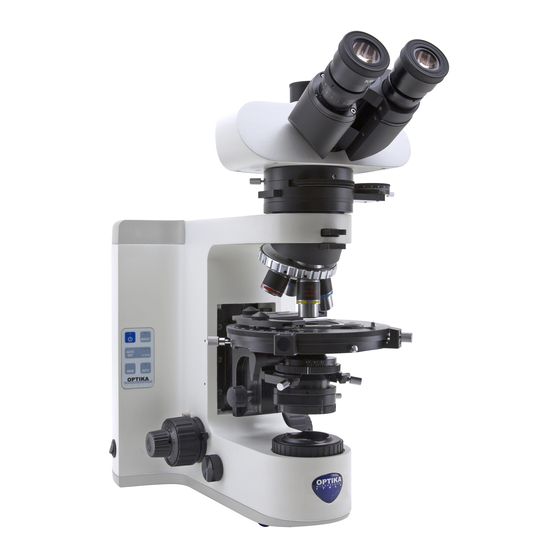
Overview DIOPTRIC ADJUSTMENT EYEPIECE RING PHOTO PORT BERTRAND LENS DISC FILTER ANALYZER PLATE HOLDER FILTER NOSEPIECE OBJECTIVE COARSE STAGE FOCUSING KNOB STAGE LOCK KNOB CONDENSER CENTERING KNOBS MAIN ON/OFF APERTURE DIAPHRAGM POLARIZER FIELD DIAPHRAGM FINE FOCUSING KNOB FOCUS-STOP KNOB BRIGHTNESS ADJUSTMENT KNOB Page 5... -
Seite 6: Unpacking
Unpacking The microscope is housed in a moulded Styrofoam container. Remove the tape from the edge of the container and lift the top half of the container. Take some care to avoid that the optical items (objectives and eyepieces) fall out and get damaged. Using both hands (one around the arm and one around the base), lift the microscope from the container and put it on a stable desk. - Seite 7 Insert the optical head above the Bertrand lens, using the other 3mm Allen wrench to tighten the screw. (Fig.2) Fig.2 Insert both eyepieces into the tubes of the optical head. (Fig.3) Fig.3 Insert the condenser under the stage: position until it is well inserted into its holder (under the condenser there is a pin that must fully enter the...
- Seite 8 Screw each objective into the thread of the nosepiece, in order of magnification. (Fig.6) Fig.6 Insert the retardation plates by sliding them into the slot under the optical head. (Fig.7) Fig.7 Center each objective using the provided screwdrivers (see chapter using the micro- scope).
- Seite 9 X-Y TRANSLATION KNOBS The rotating stage is provided with: a) Stage centering knobs; b) Stage lock knob; c) 45° rotation clicks; d) Optional X-Y translator. (Fig.10) STAGE CENTERING KNOBS Fig.10 BERTRAND LENS ATTACHMENT The Bertrand lens attachment is provided with a) Analyzer filter;...
-
Seite 10: Using The Microscope
Using the microscope Control keyboard 1) ON-OFF B-1000 illumination can be managed through 2) BOOST the keyboard placed on the left of the stand: 1) ON-OFF: press this button to turn on or off 3) AUTO-OFF the LED illuminator. 2) BOOST: press this button in order to incre- ase the brightness (useful for high-magnifica- tion objectives or very opaque specimens). -
Seite 11: Adjust The Observation Head
• The analyzer filter is in OUT position (lever fully pulled out). (Fig.16) • Photo port closed (lever on observation head fully in). Fig.16 • Bertrand lens in OUT po- sition (you read “0” on the Bertrand lens disc under the observation head). -
Seite 12: Place The Specimen On The Stage
Place the specimen on the stage Fix the specimen slide on the mechanical stage using the slide-clamp. Ensure that the specimen is centred over the stage opening. (Fig.21) Fig.21 Focus tension adjustment Turn the tension-adjust knob to get a suitable tension for the focus system. -
Seite 13: Centering The Condenser
Centering the condenser Insert the swing-out lens of the condenser ① and fully clo- se the field diaphragm ②. Ro- tate the condenser adjustment knob ③ until you see a sharp ④ image of the closed field ③ diaphragm (a bright spot of light). - Seite 14 Using the stage centering screws, bring this point in the center of the field of view. In this way the mechanical center of rotation of the stage coincides with the system’s optical axis. (Fig.28) Fig.28 Insert another objective, ro- tating the nosepiece. Repeat the above operation (stage rotations), and bring the point into the center using the...
- Seite 15 Polarizer and analyzer filters Insert or remove the lower polarizer as required. It can also be rotated at any angle. (Fig.32) Fig.32 The analyzer filter can be inserted by pushing the slider inward. By rotating the front disc, it can also be rotated at any angle.
-
Seite 16: Maintenance
Do not disassemble objectives or eyepieces in attempt to clean them. For the best results, use the OPTIKA cleaning kit (see catalogue). If you need to send the microscope to Optika for maintenance, please use the original packaging. Page 16... -
Seite 17: Troubleshooting
Troubleshooting Review the information in the table below to troubleshoot operating problems. PROBLEM CAUSE SOLUTION 1. Optical System LED does not light. Power cord is unplugged. Plug power cord into the power outlet. LED operates, but field of view Aperture and field iris diaphragms are Adjust them to proper sizes. - Seite 18 PROBLEM CAUSE SOLUTION One side of image is blurred. Objective is not correctly engaged in light Make sure that revolving nosepiece path. clicks into place correctly. Revolving nosepiece is not correctly Push slide dovetail all the way until it mounted. is stopped.
-
Seite 19: Equipment Disposal
Equipment disposal Art.13 Dlsg 25 july 2005 N°151. “According to directives 2002/95/EC, 2002/96/EC and 2003/108/EC relating to the reduction in the use of hazardous substances in electrical and electronic equipment and waste disposal.” The basket symbol on equipment or on its box indicates that the product at the end of its useful life should be collected separately from other waste. -
Seite 21: Manuale D'istruzioni
Serie B-1000 MANUALE D’ISTRUZIONI Modello B-1000POL Versione: 1 Emesso il: 25, 02, 2015... - Seite 22 Sommario Avvertenze Simboli e convenzioni Informazioni di sicurezza Applicazioni d’uso Lista accessori e ricambi Panoramica Disimballaggio Assemblaggio Uso del microscopio Manutenzione Risoluzione problemi Misure ecologiche Pagina 22...
-
Seite 23: Simboli E Convenzioni
Vi ricordiamo che il presente manuale contiene informazioni importanti sulla sicurezza e manutenzione dello strumento, e deve quindi essere accessibile a chiunque lo utilizzi. Optika declina ogni responsabilità derivante da un uso improprio dei suoi strumenti non indicato nella presente guida. -
Seite 24: Lista Accessori E Ricambi
Lista accessori e ricambi COD. DESCRIZIONE M-1001 Oculari WF10x/22mm (coppia) M-1002 Oculari WF10x/24mm (coppia) M-1004.N Telescopio di centratura per contrasto di fase, 30mm di diametro M-781 Oculare micrometrico WF10x/22mm (10mm, div.0,1mm) M-1011 Testata trinoculare (3 posizioni) M-1012 Testata binoculare ERGO M-1033 Lente di Bertrand con Analizzatore e slitta per lamine (con Lambda, ¼... -
Seite 25: Panoramica
Panoramica ANELLO REGOLAZIONE OCULARE DIOTTRICA USCITA FOTO/VIDEO LENTE DI BERTRAND ALLOGGIAMENTO FILTRO LAMINE DI RITARDO ANALIZZATORE REVOLVER OBIETTIVO MANOPOLA DI MESSA A FUOCO TAVOLINO MACROMETRICA MANOPOLA DI BLOCCO TAVOLINO MANOPOLE CENTRAGGIO PULSANTE CONDENSATORE ON/OFF DIAFRAMMA DI APERTURA POLARIZZATORE DIAFRAMMA DI CAMPO MANOPOLA MESSA A FUOCO MICROMETRICA... -
Seite 26: Disimballaggio
Disimballaggio Il microscopio è riposto in un imballo di polistirolo espanso. Rimuovere il nastro adesivo dal collo ed aprire la parte superiore dell’imballo. Fare attenzione a non far cadere le parti ottiche (obiettivi e oculari) nell’estrarre il microscopio dalla scatola per evitare che vengano danneggiati. Utilizzare entrambe le mani (una intorno allo stativo e una alla base), sfilare il microscopio dal contenitore e appoggiarlo su un piano stabile. - Seite 27 Inserire la testata ottica al di sopra della lente di Bertrand, usando la chiave a brugola da 3mm per stringere le viti. (Fig.2) Fig.2 Inserire entrambi gli oculari nei tubi portaoculari della testata ottica. (Fig.3) Fig.3 Inserire il condensatore sotto il tavolino: controllare che sia correttamente inserito nel suo alloggiamento (sotto...
- Seite 28 Avvitare ciascun obiettivo nel foro filettato del revolver, in or- dine di ingrandimento. (Fig.6) Fig.6 Inserire le lamine di ritardo facendole scorrere all’interno della slitta sotto la testata ottica. (Fig.7) Fig.7 Centrare ciascun obiettivo usando i cacciaviti in dota- zione (vedi paragrafo utilizzo microscopio).
- Seite 29 MANOPOLE DI TRASLAZIONE X-Y Il tavolino ruotante è dotato di: a) Viti di centraggio tavolino; b) Vite di fissaggio tavolino; c) clickstop di rotazione di 45°; d) movimento traslatore X-Y opzionale. (Fig.10) VITI DI CENTRAGGIO TAVOLINO Fig.10 DISPOSITIVO LENTE DI BERTRAND Il dispositivo con Lente di Bertrand è...
-
Seite 30: Utilizzo Del Microscopio
Utilizzo del microscopio Tastiera di controllo L’illuminazione del B-1000 può essere con- 1) ON-OFF 2) BOOST trollata tramite tastiera posizionata sul lato sinistro dello stativo: 1) ON-OFF: premere questo pulsante per 3) AUTO-OFF accendere/spegnere l’illuminatore LED. 2) BOOST: premere questo pulsante per incrementare la luminosità... - Seite 31 • Il filtro analizzatore sia in posizione OUT (leva tirata interamente verso l’ester- no). (Fig.16) • Uscita foto/video chiusa (leva nella testata d’osser- vazione inserita completa- mente). Fig.16 • Lente di Bertrand in posizione OUT (leggete “0” sul disco della lente di bertrand sotto la testata d’osservazione).
-
Seite 32: Regolazione Diottrica
Posizionamento del preparato sul tavolino Fissare il vetrino preparato sul tavolino traslatore utilizzando le pinzette. Assicurarsi che il preparato sia centrato sull’apertura del tavolino. (Fig.21) Fig.21 Regolazione tensione di messa a fuoco Ruotare la manopola di rego- lazione della tensione fino ad ottenere un’adeguata tensione del sistema di messa a fuoco. -
Seite 33: Centraggio Del Condensatore
Centraggio del condensatore Inserire la lente swing-out del condensatore ① e chiudere completamente il diafram- ma di campo ②. Ruotare la manopola di regolazione ④ del condensatore ③ fino ad ③ ottenere un’immagine chiara e nitida del diaframma di campo ②... - Seite 34 Usando le viti di centraggio del tavolino, porre questo pun- to al centro del campo visivo. Così il centro meccanico di rotazione del tavolino coincide con gli assi del sistema ottico. (Fig.28) Fig.28 Inserire un altro obiettivo, ruo- tando il revolver. Ripetere le operazioni come sopra (rota- zione tavolino), e porre il pun- to fisso al centro usando le viti...
- Seite 35 Filtri polarizzatore e analizzatore Inserire o rimuovere il polariz- zatore inferiore come richie- sto. Esso può essere ruotato in ogni angolazione. (Fig.32) Fig.32 Il filtro analizzatore può esse- re inserito premendo la slitta verso l’interno. Mentre ruotan- do il disco frontale può essere ruotato in goni angolazione.
-
Seite 36: Manutenzione
Non smontare mai obiettivi ed oculari con lo scopo di pulirli. Per risultati migliori, usare il cleaning kit di OPTIKA (vedere catalogo). Se è necessario spedire il vostro microscopio in Optika per manutenzione, vi preghiamo di utilizzare il suo im- ballo originale. -
Seite 37: Risoluzione Problemi
Risoluzione problemi Seguire le indicazioni della tabella sottostante per risoluzione problemi operativi. PROBLEMA CAUSA SOLUZIONE 1. Sistema ottico LED non funzionante. Il cavo di alimentazione è scollegato. Collegare il cavo di alimentazione alla presa di rete. LED funzionante, ma il campo I diaframmi di campo e di apertura non Regolare l’apertura dei diaframmi. - Seite 38 PROBLEMA CAUSA SOLUZIONE Un lato dell’immagine è L’obiettivo non è perfettamente allineato Assicurarsi che il revolver portaobiettivi sia sfocata. nel percorso ottico. agganciato. Il revolver non è correttamente montato. Inserire la coda di rondine fino a fine corsa. Il tavolino non è correttamente montato. Riposizionarlo.
-
Seite 39: Smaltimento
Smaltimento Ai sensi dell’articolo 13 del decreto legislativo 25 luglio 2005 n°151. “Attuazione delle direttive 2002/95/CE, 2002/96/CE e 2003/108/CE, relative alla riduzione dell’uso di sostanze pericolose nelle apparecchiature elettriche ed elettroniche, nonché allo smaltimento dei rifiuti”. Il simbolo del cassonetto riportato sulla apparecchiatura o sulla sua confezione indica che il prodotto alla fine della propria vita utile deve essere raccolto separatamente degli altri rifiuti. - Seite 41 Serie B-1000 MANUAL DEL USUARIO Modelo B-1000POL Versión: Fecha: 25, 02, 2015...
- Seite 42 Indice Advertencia Simbolos Información de seguridad Utilización Contenido Vista en general Desembalaje Montaje Trabajar con el microscopio Mantenimiento Problemas y soluciones Eliminación de residuos Página 42...
-
Seite 43: Información De Seguridad
Le recordamos leer este manual el cual contiene información importante sobre seguridad y man- tenimiento, y ser accesible a los usuarios de los instrumentos. Optika declina toda responsabilidad derivada del uso incorrecto del equipo y no sea conforme con el presente manual Simbolos La siguiente lista le muestra los símbolos que se utilizan en este manual... - Seite 44 Contenido CÓDIGO DESCRIPTION M-1001 Ocular WF10x/22mm (par) M-1002 Ocular WF10x/24mm (par) M-1004.N Ocular telescópico para centrar los anillos de contraste de fases, 30mm de diámetro M-781 Ocular micrométrico WF10x/22mm (10mm, div. 0,1mm) M-1011 Cabezal trinocular (3 posiciones) M-1012 Cabezal binocular ERGO M-1033 Lente Bertrand con Analizador y ranura par insertar filtros (con Lambda, 1/4 Lambda y cuña de Quarzo)
-
Seite 45: Vista En General
Vista general ANILLO DE AJUSTE DIÓPTRICO OCULAR TUBO TRINOCULAR DISCO DE LENTE DE BERTRAND SOPORTE PARA FILTRO PLACA DE FILTROS ANALIZADOR REVOLVER MANDO DE OBJETIVO ENFOQUE MACRO Y PLATINA MICROMETRICO TORNILLO FIJACIÓN PLATINA MANDOS PARA BOTON DE CENTRAR EL ENCENDIDO/ CONDENSADOR APAGADO APERTURA... -
Seite 46: Desembalaje
Desembalaje El microscopio está guardado en una caja de porexpan. Retire la cinta adhesiva alrededor de la caja y levante la tapa superior. Tenga cuidado al levantar la tapa ya que algunos accesorios ópticos (objetivos y oculares) podrían caerse y dañarse. Con las dos manos (una alrededor del estativo y otra debajo la base), levante el microscopio y pongalo sobre una mesa estable. - Seite 47 Insertar el cabezal sobre el módulo de la Lente de Ber- trand. Con la llave Allen de 3mm fijar el cabezal. (Fig.2) Fig.2 Insertar ambos oculares en los tubos porta ocular del cabezal. (Fig.3) Fig.3 Colocar el condensador bajo la platina e insertar en dicha posición hasta que quede bien ubicado en su soporte.
- Seite 48 Colocar cada objetivo en el revolver por orden de menor a mayor aumento. (Fig.6) Fig.6 Insertar la placa de retarda- ción deslizándola hacia dentro del soporte que hay debajo del cabezal óptico. (Fig.7) Fig.7 Centrar cada uno de los objetivos utilizando el destor- nillador suministrado.
- Seite 49 MANDOS DE TRASLACIÓN DE MOVIMIENTO X-Y La platina giratoria está provi- sto de: a) Mandos para centrar la platina; b) Tornillo de fijación de la platina; c) Sistema de paro “click” para la rotación de 45°; d) Opcional, platina mecánica X-Y.
- Seite 50 Utilizar el microscopio Control a través de los botones La iluminación en el modelo B-1000 se puede 1) ON-OFF 2) BOOST ajustar mediante los botones ubicado a la izquierda del estativo: 1) ON-OFF: 1) presione éste boton para en- 3) AUTO-OFF cender o apagar la luz LED.
-
Seite 51: Ajustar La Distancia Interpupilar
• El analizador esté en posición OUT (la palanca está completamete hacia afuera). (Fig.16) • Salida de fotografía cerrado. (La palanca del cabezal está completa- mente hacia dentro). Fig.16 • Lente Bertrand está en posición OUT (verá “0” en el disco de la lente Bertrand ubicado bajo el cabezal). -
Seite 52: Ajuste Dióptrico
Colocar la muestra seobre la platina Fije la muestra con la pinza del carro mecánico de la pla- tina porta preparados. Mueva el carro mecánico hasta que la muestra quede en el centro de la platina. (Fig.21) Fig.21 Ajustar la tensión del mando de enfoque Girar el aro de tensión de los mandos hasta conse-... - Seite 53 Centrar el condensador Insertar la lente abatible del condensador ① y cierre com- pletamente el diafragma de campo ②. Girar el mando de ajuste en altura del conden- ④ sador ③ hasta conseguir ver ③ una imagen del punto de luz que aparece con el condensa- ②...
- Seite 54 Usando los tornillo para cen- trar la platina, traer este punto en el centro del campo de vista. De esta manera el cen- tro mecánico de rotación de la platina coincide con el eje óptico del sistema. (Fig.28) Fig.28 Insertar el siguiente objetivo, girar el revolver y repita la operación anterior (rotación de la platina) y traer el punto...
- Seite 55 Filtros polarizador y analizador Insertar o quitar el polarizador inferior según sea necesario. También se puede girar en cualquier ángulo. (Fig.32) Fig.32 El filtro del analizador se inserta en la ranura que se encuentra en el cabezal para dicha función. El analizador es giratorio para observar diferentes ángulos.
-
Seite 56: Mantenimiento
No desmonte las lentes interiores de objetivos y oculares para limpiar su interior. Para obtener los mejores resultados, utilice el kit de limpieza OPTIKA. Si necesita enviar el microscopio a Optika para su mantenimiento, por favor, utilice el embalaje original. Página 56... -
Seite 57: Problemas Y Soluciones
Problemas y soluciones Revise la tabla inferior para encontrar soluciones a posibles problemas con el microscopio. PROBLEMA CAUSA SOLUCIÓN 1. Sistema óptico No se enciende el LED. No está conectado el cable de cor- Conectar el cable de corriente. riente. LED funciona pero la visión es Diafragmas de apertura iris y de Ajustar ambos diafragmas abriendo poco a... - Seite 58 PROBLEMA CAUSA SOLUCIÓN Un lado de la imagen es bor- El objetivo no está correctamente en el Asegúrese de que Revólver encaje cor- rosa. centro del eje de iluminación rectamente. El revólver portaobjetivos no está correc- Compruebe que el revolver esta insertado tamente montado.
-
Seite 59: Eliminación De Residuos
Eliminación de residuos En conformidad con el Art. 13 del D.L. de 25 julio 2005 n°151. Actuación de las Directivas 2002/95/CE, 2002/96/ CE y 2003/108/CE, relativas a la reducción del uso de sustancias peligrosas en la instrumentación eléctrica y electrónica y a la eliminación de residuos. El símbolo del contenedor que se muestra en la instrumentación o en su embalaje indica que el producto cuando alcanzará... - Seite 60 Página 60...
- Seite 61 Série B-1000 MANUEL D’INSTRUCTIONS Modèle B-1000POL Version: 25, 02, 2015...
- Seite 62 Sommaire Avertissement Symboles Précautions de securité Usage Liste des accessoires et pièces de rechange Vue d’ensemble Déballage Installation du microscope Utilisation du microscope Entretien Résolution de problèmes Ramassage Page 62...
-
Seite 63: Symboles
Avertissement Le présent microscope est un appareil scientifique de précision d’une durée de vie de plusieurs années et un entretien minimum. Les meilleurs composants optiques et mécaniques ont été utilisés pour sa conception ce qui fond de cet instrument un appareil idéal pour une utilisation journalière. Ce guide contient des informations importantes sur la sécurité... -
Seite 64: Liste Des Accessoires Et Pièces De Rechange
Liste des accessoires et pièces de recharge RÉF. DESCRIPTION M-1001 Oculaires WF10x/22mm (la paire) M-1002 Oculaires WF10x/24mm (la paire) M-1004.N Télescope de centrage pour contraste de phase, diamètre de 30mm M-781 Oculaire micrométrique EWF10x/22mm M-1011 Trinocular Head (3 positions) M-1012 Tête binoculaire ERGO M-1033 Lentille de Bertrand avec analyseur et ouverture pour glissières Lambda (avec Lambda,... -
Seite 65: Vue D'ensemble
Vue d’ensemble ANNEAU DE RÉGLAGE DIOPTRIQUE OCULAIRE PORT PHOTO/VIDÉO LENTILLE DE BERTRAND BLOQUAGE DES FILTRE FILTRES ANALYSEUR REVOLVER OBJECTIF MISE AU POINT MACROMÉTRIQUE PLATINE VIS DE BLOCAGE DE LA ROTATION DE LA PLATINE VIS DE CENTRAGE INTERRUPTEUR DU CONDENSEUR PRINCIPAL ON/OFF DIAPHRAGME D’OUVERTURE POLARISEUR... -
Seite 66: Déballage
Déballage Le microscope est livré dans un emballage en polystyrène. Après avoir ouvert l’emballage, enlever la partie supérieure de la boîte. Operer attentivement afin d’éviter d’endommager les composants optiques (objectifs et oculaires) et afin d’éviter que l’instrument tombe. Enlever le microscope de son emballage avec les deux mains (avec une main soutenez le bras et avec l’autre la base) puis l’appuyer sur une superficie stable et platte. - Seite 67 Insérer la tête optique au des- sus de la lentille de Bertrand en utilisant l’autre clé Allen 3mm pour serrer la vis. (Fig.2) Fig.2 Insérer les deux oculaires dans les tubes de la tête opti- que. (Fig.3) Fig.3 Insérer le condenseur sous la platine: veiller à...
- Seite 68 Visser chaque objectif dans le filetage de la tourelle, par or- dre de grossissement. (Fig.6) Fig.6 Insérer les lames de retard en les faisant glisser dans le logement sous la tête optique. (Fig.7) Fig.7 Centrer chaque objectif en utilisant les tournevis fournis (voir chapitre utilisation du microscope).
- Seite 69 COMMANDES DE TRANSLATION X-Y La platine tournante est fournie avec: a) Commandes de centrage de la platine; b) Commande de blocage de la platine; c) clics de rotation tous les 45°; d) Translateur X-Y optionnel. (Fig.10) COMMANDES DE CENTRAGE DE LA PLATINE Fig.10 LENTILLE DE BERTRAND La lentille de Bertrand est...
-
Seite 70: Utilisation Du Microscope
Utilisation du microscope Clavier de contrôle L’éclairage du B-1000 peut être gérée par le 1) ON-OFF 2) BOOST clavier placé sur la gauche du statif: 1) ON-OFF: appuyer sur ce bouton pour allu- mer ou éteindre l’illuminateur LED . 3) AUTO-OFF 2) BOOST: appuyer sur ce bouton pour au- gmenter la luminosité... -
Seite 71: Réglage De La Distance Interpupillaire
• Le filtre analyseur est en position OUT (levier com- plètement retiré). (Fig.16) • Port photo fermé (le- vier inseré dans la tête d’observtion). Fig.16 • La lentille de Bertrand en position OUT (vous lisez “0” sur le disque de la lentille de Bertrand sous la tête d’observation). -
Seite 72: Réglage Dioptrique
Placer l’échantillon sur la platine Fixer l’ échantillon sur la platine mécanique utilisant la pince coulissante. Assurez- vous que l’échantillon est centré sur l’ouverture de la platine. (Fig.21) Fig.21 Réglage de la mise au point Tourner le bouton de réglage de tension pour obtenir une tension appropriée pour la mise au point. - Seite 73 Centrer le condenseur Insérer la lentille amovible du condenseur ①et fermer com- plètement le diaphragme de champ ②. Tourner la com- mande de réglage du con- ④ denseur ③ jusqu’à voir une ③ image nette du diaphragme de champ fermé (un point ②...
- Seite 74 En utilisant la vis de centrage de la platine, porter ce point au centre du champ de vision. De cette manière, le centre de rotation mécanique de la plati- ne coïncide avec l’axe optique du système. (Fig.28) Fig.28 Insérer un autre objectif, en tournant le revolver.
- Seite 75 Filtres polariseur et analyseur Insérer ou retirer le polariseur inférieur. Il peut également être mis en rotation à n’impor- te quel angle. (Fig.32) Fig.32 Le filtre analyseur peut être inséré en poussant le cou- lisseau vers l’intérieur. En tournant le disques frontale, il peut également être mis en rotation à...
-
Seite 76: Réparation Et Entretien
• Les empreintes digitales peuvent endommager les parties optiques. Pour les meilleurs résultats, utiliser le kit de nettoyage OPTIKA (voir le catalogue). Conserver l’emballage d’origine dans le cas où il serait nécessaire de retourner le microscope au fournisseur pour un entretien ou une réparation. -
Seite 77: Résolution De Problèmes
Résolution des problèmes Reportez-vous à l’information dans le tableau ci-dessous pour résoudre les problèmes opérationnels. PROBLEME CAUSE SOLUTION 1. Système optique La LED ne s’allume pas. Le cordon d’alimentation est débran- Branchez le cordon d’alimentation dans la ché. prise d’alimentation. La LED est allumée, mais le Les diaphragmes d’ouverture et de Régler aux bonnes dimensions. - Seite 78 PROBLEME CAUSE SOLUTION Une partie de l’image est L’objectif est mal engagé dans le trajet La tourelle porte-objectifs doit être enclen- floue. optique. chée jusqu’au clic. La tourelle porte-objectifs n’est pas bien Appuyer fermement sur l’encoche en montée. forme d’aronde jusqu’à la butée. La platine est mal montée.
-
Seite 79: Ramassage
Ramassage Conformément à l’Article 13 du D.L du 25 Juillet 2005 nº151 Action des Directives 2002/95/CE, 2002/96/CE et 2003/108/CE, relatives à la réduction de l’utilisation de substances dangereuses dans l’appareil électrique et électronique et à l’élimination des résidus. Le Symbole du conteneur qui figure sur l’appareil électrique ou sur son emballage indique que le produit devra être, à... - Seite 81 B-1000 Serie BEDIENUNGSANLEITUNG Modell B-1000POL Version: Datum: 25, 02, 2015...
- Seite 82 Inhalt Hinweis Wartung- und Gefahrzeichen Vorsichtsmaßnahmen Verwendung Inhalt Beschreibung Auspacken Montage Verwendung des Mikroskops Wartung Probleme und Lösungen Wiederverwertung Pagina 82...
-
Seite 83: Wartung- Und Gefahrzeichen
Standards und zum täglichen Gebrauch hergestellt. Diese Bedienungsanleitung enthält wichtige Informationen zur korrekten und sicheren Benutzung des Geräts. Diese Anleitung soll allen Benutzern zur Verfügung stehen. Optika lehnt jede Verantwortung für eine fehlerhafte, in dieser Bedienungsanleitung nicht gezeigten Verwend- ung Ihrer Produkte ab. -
Seite 84: Beschreibung
Inhalt CODE BESCHREIBUNG M-1001 Okulare WF10x/22mm (Paar) M-1002 Okulare WF10x/24mm (Paar) M-1004.N Zentrierungsteleskop für Phasenkontrast , 30mm Durchmesser M-781 Mikrometrisches Okular WF10x/22mm (10mm, Teil. 0,1mm) M-1011 Trinokularer Kopf (3 Position) M-1012 ERGO binokularer Kopf M-1033 Bertrand Linse mit Analysator und Schlitz für Slides (mit Lambda, ¼ Lambda und Quarzkeil) M-1044 5-fach Revolver mit Zentrierungssystem für POL Objektive M-1080... - Seite 85 Beschreibung OKULAR DIOPTRIENVERSTELLUNGSRING USCITA FOTO/VIDEO BERTRAND-LINSE SCHEIBE HALTERUNG FÜR ANALYSEFILTER FILTERPLATTE REVOLVER OBJEKTIV GROBTRIEBDREHKNOPF DREHTISCH DREHTISCH- SPERRKNOPF KONDENSOR-ZENTRIE- ON/OFF RUNGSKNÖPFE SCHALTER APERTURBLENDE POLARISATOR FELDBLENDE FEINTRIEBDREHKNOPF SCHARFSTELLUNGSFESTHALTUNG LICHTEINSTELLUNG Pagina 85...
-
Seite 86: Auspacken
Auspacken Das Mikroskop ist in einer Schachtel aus Styroporschicht enthalten. Entfernen Sie das Klebeband von der Schachtel und öffnen Sie mit Vorsicht den oberen Teil, ohne Objektive und Okulare zu beschädigen. Mit beiden Händen (eine um dem Stativ und eine um der Basis) ziehen Sie das Mikroskop aus der Schachtel heraus und stellen Sie es auf eine stabile Oberfläche. - Seite 87 Setzen Sie den optischen Kopf auf das Modul der Ber- trand-Linse an. Mit dem 3 mm Imbusschlüssel befestigen Sie den Kopf. (Abbildung 2) Fig.2 Führen Sie beide Okulare in die Röhrenöffnungen ein. (Abbildung 3) Fig.3 Setzen Sie den Kondensor unter den Kreuztisch ein, so dass er sich in seiner Hal- terung befindet (unter dem WENN DER KONDENSOR...
- Seite 88 Schrauben Sie jedes Objektiv nach Vergrößerung (von der kleinsten bis der grössten Ver- größerung) in den Revolver ein. (Abbildung 6) Fig.6 Setzen Sie die Verzöge- rungsplatte ein, während Sie sie in den Schlitz unter dem optischen Kopf schieben (Abbildung 7) Fig.7 Zentrieren Sie jedes Objektiv mithilfe des mitgelieferten...
- Seite 89 X-Y KREUZTISCHBEWEGUNG Der Drehtisch wird mit Folgen- des geliefert: a) Drehtisch-Zentrie- rungsknöpfe; b) Befestigungsschraube; c) 45° Drehung-Click; d) Optionell, X-Y Kreuztisch (Abbildung 10) DREHTISCH-ZENTRIERUNGSKNÖPFE Fig.10 BERTRAND-LINSE MODUL Das Bertrand-Linse-Modul wird mit Folgendes mitgelie- fert: a) Analysefilter; b) Verzögerungsplatten; c) Linsenfokuseinstellung; d) X-Y Zentrierungsschrauben für die Linsen (Abbildung 11) Fig.11...
-
Seite 90: Verwendung Des Mikroskops
Verwendung des Mikroskops Steuerungstastatur Die Beleuchtung des B-1000 kann durch die 1) ON-OFF 2) BOOST Tastatur an der linken Seite des Stativs einge- stellt werden: 1) ON-OFF: drücken Sie diese Taste, um die 3) AUTO-OFF LED Beleuchtung an- und auszuschalten. 2) BOOST: drücken Sie diesen Knopf, um die Beleuchtung zu erhöhen (nützlich bei Objekti- ve mit grosser Vergrößerung oder bei sehr... -
Seite 91: Einstellung Des Kopfes
• Der Analysefilter ist im Position OUT (der Hebel ist völlig nach außen). (Abbildung 16) • Foto-Ausgang geschlos- sen (der Hebel auf dem Kopf ist völlig nach innen). Fig.16 • Die Bertrand-Linse ist im Position OUT (Auf der Bertrand-Linse -Scheibe unter dem Kopf werden Sie “0”... -
Seite 92: Objektträger Auf Den Tisch Legen
Objektträger auf den Tisch legen Befestigen Sie den Objektträger auf den Kreuztisch mit Hilfe der dafür vorgesehenen Klemmen. Vergewissern Sie sich, dass der Objektträger über der Öffnung des Kreuztisches zentriert ist. Fig.21 (Abbildung 21) Fokusspannungsein- stellung Drehen Sie den Knopf für die Spannungseinstellung, um die bestmögliche Spannung zu erreichen. -
Seite 93: Einstellung Des Kondensors
Einstellung des Kondensors Legen Sie die Swing-out Linse des Kondensors ① ein und schliessen Sie die Feldblende völlig ②. Ruotare la manopola di regolazione del conden- ④ satore ③ Drehen Sie den ③ Kondensorzentrierungsknob, bis ein scharfes Bild des ② Lichtpunktes bei geschlosse- Fig.25 ①... - Seite 94 Mit den Zentrierungsschrau- ben des Drehtisches bringen Sie diesen Punkt zur Mitte des Sichtfeldes. Auf dieser Wei- se stimmt die mechanische Drehungszentrum des Tisches mit der optischen Achse des Systems überein.(Abbildung Fig.28 Setzen Sie ein weiteres Objektiv ein und drehen Sie den Revolver.
-
Seite 95: Polarisator- Und Analysefilter
Polarisator- und Analysefilter Legen Sie den unteren Pola- risator ein oder entfernen Sie ihn wie gewünscht. Er kann auch um jeden Winkel gedreht werden (Abbildung 32) Fig.32 Der Analysefilter muss in den dazu bestimmten Schlitz ein- gesetzt werden. Beim drehen der Vorderplatte kann er auch um jeden Winkel gedreht wer- den. -
Seite 96: Wartung
Montieren Sie die Objektive und Okulare nicht ab, um sie zu reinigen. Am Besten verwenden Sie das OPTIKA Reinigungskit (siehe Katalog) Falls das Mikroskop aus Wartungszwecken an Optika zurückgeschickt werden muss, verwenden Sie bitte im- mer die Originalverpackung. Pagina 96... -
Seite 97: Probleme Und Lösungen
Probleme und Lösungen Siehe bitte die Tabelle hier unten für Lösungen an mögliche Probleme mit dem Mikroskop. PROBLEM URSACHE LÖSUNG 1. Optisches System Die LED beleuchtet nicht. Das Netzkabel ist nicht verbindet Das Netzkabel verbinden. Die LED funktioniert aber das Apertur- und Irisfeldblende sind nicht Beide Blenden verstellen. - Seite 98 PROBLEM URSACHE LÖSUNG Eine Seite des Bildes ist un- Das Objektiv ist in dem optischen Weg Vergewissern Sie sich, dass der Revolv- scharf. nicht korrekt zentriert. er in der korrekten Position ist. Der Revolver ist nicht richtig montiert. Vergewissern Sie sich, dass der Revolver in der korrekten Position ist.
-
Seite 99: Wiederverwertung
Wiederverwertung Gemäß dem Artikel 13 vom Dekret Nr. 151 vom 25.07.2005 “Umsetzung der Richtlinien 2002/95/EG, 2002/96/EG und 2003/108/EG in Bezug auf die Verwendung gefährlicher Stoffe in elektrischen und elektronischen Geräten sowie die Abfallentsorgung” Das Symbol vom Müllcontainer erscheint auf dem Gerät oder der Verpackung und weist darauf hin, dass das Produkt Ende des Lebens separat von anderen Abfällen entsorgt werden muss. - Seite 100 OPTIKA S.r.l. ® Via Rigla, 30 - 24010 Ponteranica (BG) - ITALIA Tel.: +39 035.571.392 - Fax: +39 035.571.435 info@optikamicroscopes.com - www.optikamicroscopes.com OPTIKA Spain ® spain@optikamicroscopes.com OPTIKA USA ® usa@optikamicroscopes.com OPTIKA China ® china@optikamicroscopes.com OPTIKA Hungary ® hungary@optikamicroscopes.com...