Herunterladen Inhalt Inhalt Diese Seite drucken

Werbung

Verfügbare Sprachen
  • DE

Verfügbare Sprachen

  • DEUTSCH, seite 66
500 Series
Version:
7
Issued:
16, 03, 2017
INSTRUCTION MANUAL
Model
B-500BSp
B-500TSp
B-500Bpl
B-500Tpl
B-500Bi
B-500Ti
B-500ERGO
B-500iERGO
B-500Bph
B-500Tph
B-500Biph
B-500Tiph
B-500Ti-2
B-500Ti-3
B-500Ti-5
B-500ASB
B-500Ti2F

Werbung

Inhaltsverzeichnis
loading

Inhaltszusammenfassung für Optika 500 Series

  • Seite 1 500 Series INSTRUCTION MANUAL Model B-500BSp B-500TSp B-500Bpl B-500Tpl B-500Bi B-500Ti B-500ERGO B-500iERGO B-500Bph B-500Tph B-500Biph B-500Tiph B-500Ti-2 B-500Ti-3 B-500Ti-5 B-500ASB B-500Ti2F Version: Issued: 16, 03, 2017...
  • Seite 2: Inhaltsverzeichnis

    Table of Contents Warning Symbols and conventions Safety Information Intended use List of accessories and spare parts Overview Unpacking Assembling Using the microscope Maintenance Troubleshooting Equipment disposal Page 2...
  • Seite 3: Symbols And Conventions

    Warning This microscope is a scientific precision instrument designed to last for many years with a minimum of mainte- nance. It is built to high optical and mechanical standards and to withstand daily use. We remind you that this manual contains important information on safety and maintenance, and that it must therefore be made acces- sible to the instrument users.
  • Seite 4: List Of Accessories And Spare Parts

    M-113.1 Ring adapter, 30mm (for monocular and binocular microscopes) M-778 C-mount adapter for 1/3”,1/2” and 2/3” sensor M-666.500 Heating stage, with digital temperature controller B-500 series M-666.500ph Heating stage, with digital temperature controller B-500Ph 15008 OPTIKA immersion oil 10ml Page 4...
  • Seite 5: Overview

    Overview DIOPTRIC ADJUSTMENT RING EYEPIECE NOSEPIECE OBJECTIVE TENSION ADJUSTEMENT STAGE KNOB CONDENSER CENTERING KNOBS APERTURE DIAPHRAGM COARSE FINE FOCUSING FOCUSING KNOB KNOB TRANSLATION KNOB FIELD DIAPHRAGM Page 5...
  • Seite 6: Unpacking

    Unpacking The microscope is housed in a moulded Styrofoam container. Remove the tape from the edge of the container and lift the top half of the container. Take some care to avoid that the optical items (objectives and eyepieces) fall out and get damaged. Using both hands (one around the arm and one around the base), lift the microscope from the container and put it on a stable desk.
  • Seite 7 Insert both eyepieces into the tubes of the optical head. (Fig.2) Fig.2 Insert the condenser under the stage: position until it is well inserted into its holder (under the condenser there is a pin that must fully enter the guide of the holder). (Fig. 3) Fig.3 Mount the stage: lower the support using the coarse...
  • Seite 8 Insert the power supply cable on the connector at the rear. (Fig.6) Fig.6 Page 8...
  • Seite 9: Using The Microscope

    Using the microscope LED settings In order to activate the transmitted light illumi- nator, insert the plug of the power supply cable into the socket and turn on the main switch on the back of the main body. Turn the brightness adjustment knob to a brightness suitable for observation.
  • Seite 10: Diopter Adjustment

    Focus tension adjustment Turn the tension-adjust knob to get a suitable tension for the focus system. (Fig.11) NOTE: if the tension is too lo- ose, the stage could go lower by itself or the focus easily lost after fine adjustment. In this case, rotate the knob in order to increase the friction.
  • Seite 11: Centering The Condenser

    Centering the condenser Insert the swing-out lens of the condenser ① and fully clo- se the field diaphragm ②. Ro- tate the condenser adjustment ④ knob ③ until you see a sharp image of the closed field diaphragm (a bright spot of ②...
  • Seite 12: Maintenance

    Do not disassemble objectives or eyepieces in attempt to clean them. For the best results, use the OPTIKA cleaning kit (see catalogue). If you need to send the microscope to Optika for maintenance, please use the original packaging. Page 12...
  • Seite 13: Troubleshooting

    Troubleshooting Review the information in the table below to troubleshoot operating problems. PROBLEM CAUSE SOLUTION 1. Optical System LED does not light. Power cord is unplugged. Plug power cord into the power outlet. LED operates, but field of view Aperture and field iris diaphragms are Adjust them to proper sizes.
  • Seite 14 PROBLEM CAUSE SOLUTION One side of image is blurred. Objective is not correctly engaged in light Make sure that revolving nosepiece path. clicks into place correctly. Revolving nosepiece is not correctly Push slide dovetail all the way until it mounted. is stopped.
  • Seite 15: Equipment Disposal

    Equipment disposal Art.13 Dlsg 25 july 2005 N°151. “According to directives 2002/95/EC, 2002/96/EC and 2003/108/EC relating to the reduction in the use of hazardous substances in electrical and electronic equipment and waste disposal.” The basket symbol on equipment or on its box indicates that the product at the end of its useful life should be collected separately from other waste.
  • Seite 17: Manuale D'istruzioni

    Serie B-500 MANUALE D’ISTRUZIONI Modelli B-500BSp B-500TSp B-500Bpl B-500Tpl B-500Bi B-500Ti B-500ERGO B-500iERGO B-500Bph B-500Tph B-500Biph B-500Tiph B-500Ti-2 B-500Ti-3 B-500Ti-5 B-500ASB B-500Ti2F Versione: 7 Emesso il: 16, 03, 2017...
  • Seite 18 Sommario Avvertenze Simboli e convenzioni Informazioni di sicurezza Applicazioni d’uso Lista accessori e ricambi Panoramica Disimballaggio Assemblaggio Uso del microscopio Manutenzione Risoluzione problemi Misure ecologiche Pagina 18...
  • Seite 19: Simboli E Convenzioni

    Vi ricordiamo che il presente manuale contiene informazioni importanti sulla sicurezza e manutenzione dello strumento, e deve quindi essere accessibile a chiunque lo utilizzi. Optika declina ogni responsabilità derivante da un uso improprio dei suoi strumenti non indicato nella presente guida.
  • Seite 20: Lista Accessori E Ricambi

    Anello adattatore, 30mm (per microscopi monoculari e binoculari) M-778 Adattatore C-Mount per sensori 1/3”,1/2” e 2/3” M-666.500 Tavolino riscaldante, con controllo digitale della temperatura per B-500 M-666.500ph Tavolino riscaldante, con controllo digitale della temperatura per B-500Ph 15008 OPTIKA olio da immersione 10ml Pagina 20...
  • Seite 21: Panoramica

    Panoramica COMPENSAZIONE DIOTTRICA OCULARI REVOLVER OBIETTIVI REGOLAZIONE TENSIONE FOCUS TAVOLINO MANOPOLE DI CENTRAGGIO CONDENSATORE DIAFRAMMA DI APERTURA FOCUS MACROMETRICO MANOPOLA DI TRASLAZIONE FOCUS MICROMETRICO DIAFRAMMA DI CAMPO Pagina 21...
  • Seite 22: Disimballaggio

    Disimballaggio Il microscopio è riposto in un imballo di polistirolo espanso. Rimuovere il nastro adesivo dal collo ed aprire la parte superiore dell’imballo. Fare attenzione a non far cadere le parti ottiche (obiettivi e oculari) nell’estrarre il microscopio dalla scatola per evitare che vengano danneggiati. Utilizzare entrambe le mani (una intorno allo stativo e una alla base), sfilare il microscopio dal contenitore e appoggiarlo su un piano stabile.
  • Seite 23 Inserire entrambi gli oculari nei tubi portaoculari della testata ottica. (Fig.2) Fig.2 Inserire il condensatore sotto il tavolino: controllare che sia correttamente inserito nel suo alloggiamento (sotto il condensatore si trova uno spinotto che deve entrare completamente nella guida dell’alloggiamento). (Fig.3) Fig.3 Montare il tavolino: abbas- sare il supporto mediante la...
  • Seite 24 Inserire il cavo di alimentazio- ne nel connettore sul retro. (Fig.6) Fig.6 Pagina 24...
  • Seite 25: Uso Del Microscopio

    Uso del microscopio REGOLAZIONE LED Per attivare l’illuminatore in luce trasmessa, inserire la spina dell’alimentatore esterno nella presa di rete ed accendere l’interruttore princi- pale sul retro dello stativo. Ruotare la manopola di regolazione della luminosità fino ad ottenere la luminosità adeguata all’osserva- zione.
  • Seite 26: Regolazione Diottrica

    Regolazione tensione di messa a fuoco Ruotare la manopola di rego- lazione della tensione fino ad ottenere un’adeguata tensione del sistema di messa a fuoco. (Fig.11) NOTA: se la tensio- ne è troppo bassa, il tavolino tende a scendere da solo ver- so il basso o la messa a fuoco viene persa facilmente dopo la regolazione micrometrica.
  • Seite 27: Centraggio Del Condensatore

    Centraggio del condensatore Inserire la lente swing-out del condensatore ① e chiudere completamente il diaframma di campo ②. Ruotare ④ la manopola di regolazione del condensatore ③ fino ad ottenere un’immagine chiara e ② nitida del diaframma di campo chiuso (un cerchio luminoso). Fig.14 ③...
  • Seite 28: Manutenzione

    Non smontare mai obiettivi ed oculari con lo scopo di pulirli. Per risultati migliori, usare il cleaning kit di OPTIKA (vedere catalogo). Se è necessario spedire il vostro microscopio in Optika per manutenzione, vi preghiamo di utilizzare il suo im- ballo originale.
  • Seite 29: Risoluzione Problemi

    Risoluzione problemi Seguire le indicazioni della tabella sottostante per risoluzione problemi operativi. PROBLEMA CAUSA SOLUZIONE 1. Sistema ottico LED non funzionante. Il cavo di alimentazione è scollegato. Collegare il cavo di alimentazione alla presa di rete. LED funzionante, ma il campo I diaframmi di campo e di apertura non Regolare l’apertura dei diaframmi.
  • Seite 30 PROBLEMA CAUSA SOLUZIONE Un lato dell’immagine è L’obiettivo non è perfettamente allineato Assicurarsi che il revolver portaobiettivi sia sfocata. nel percorso ottico. agganciato. Il revolver non è correttamente montato. Inserire la coda di rondine fino a fine corsa. Il tavolino non è correttamente montato. Riposizionarlo.
  • Seite 31 Pagina 31...
  • Seite 32 Pagina 32...
  • Seite 33 Serie B-500 MANUAL DEL USUARIO Models B-500BSp B-500TSp B-500Bpl B-500Tpl B-500Bi B-500Ti B-500ERGO B-500iERGO B-500Bph B-500Tph B-500Biph B-500Tiph B-500Ti-2 B-500Ti-3 B-500Ti-5 B-500ASB B-500Ti2F Versión: Fecha: 16, 03, 2017...
  • Seite 34 Indice Advertencia Símbolos Información de seguridad Utilización Contenido Vista en general Desembalaje Montaje Trabajar con el microscopio Mantenimiento Problemas y soluciones Eliminación de residuos Página 34...
  • Seite 35: Información De Seguridad

    Le recordamos leer este manual el cual contiene información importante sobre seguridad y man- tenimiento, y debe ser accesible a los usuarios de los instrumentos. Optika declina toda responsabilidad deri- vada del uso incorrecto del equipo y que no sea conforme con el presente manual.
  • Seite 36 Adaptador de anillo de 30mm (para microscopios monoculares y binoculares) M-778 Adaptador C-mount para sensores de 1/3”,1/2” y 2/3” M-666.500 Platina calefactora para B-500, con controlador digital de temperatura M-666.500ph Platina calefactora para B-500Ph, con controlador digital de temperatura 15008 Aceite inmersión OPTIKA 10ml Página 36...
  • Seite 37: Vista En General

    Vista general ANILLO AJUSTE DIOPTRICO OCULAR REVOLVER OBJETIVO MANDO AJUSTE DE TENSIÓN PLATINA TORNILLOS PARA CENTRAR EL CONDENSADOR DIAFRAGMA MANDO MACROME-TRICO MANDOS DE MANDO TRASLACIÓN MICROMETRICO DIAFRAGMA DE CAMPO Página 37...
  • Seite 38: Desembalaje

    Desembalaje El microscopio está guardado en una caja de porexpan. Retirar la cinta adhesiva alrededor de la caja y levan- tar la tapa superior. Tener cuidado al levantar la tapa ya que algunos accesorios ópticos (objetivos y oculares) podrían caerse y dañarse. Con las dos manos (una alrededor del estativo y otra debajo la base), levantar el microscopio y ponerlo sobre una mesa estable.
  • Seite 39 Insertar ambos oculares en los tubos porta ocular del cabezal. (Fig.2) Fig.2 Colocar el condensador bajo la platina: insertar en dicha posición hasta que quede bien ubicado en su soporte. (bajo el condensador hay una tuerca que debe entrar de lleno en la guía del condensa- dor).
  • Seite 40 Insertar el cable suministra- do en el conector de la parte trasera. (Fig.6) Fig.6 Página 40...
  • Seite 41: Trabajar Con El Microscopio

    Trabajar con el microscopio Configuración LED Para activar la iluminación transmitida, en- chufar a la corriente y encender con el botón principal situado en la parte trasera. Girar el botón de ajuste de intensidad de luz hasta conseguir el nivel de iluminación deseado para la observación.
  • Seite 42: Ajuste Dióptrico

    Ajustar la tensión del mando de enfoque Girar el aro de tensión de los mandos hasta conseguir una rotación suave del mando ma- crométrico y que le sea cómodo para trabajar. (Fig.11) NOTE: Si la tensión es demasiado floja (suave) la platina puede deslizarse hacia abajo ella sola.
  • Seite 43 Centrar el condensador Insertar la lente abatible del condensador ① y cerrar com- pletamente el diafragma de campo ②. Girar el mando de ④ ajuste en altura del conden- sador ③ hasta conseguir ver una imagen del punto de luz ②...
  • Seite 44: Mantenimiento

    No desmonte las lentes interiores de objetivos y oculares para limpiar su interior. Para obtener los mejores resultados, utilizar el kit de limpieza OPTIKA. Si necesita enviar el microscopio a Optika para su mantenimiento, por favor, utilice el embalaje original. Página 44...
  • Seite 45: Problemas Y Soluciones

    Problemas y soluciones Revisar la tabla inferior para encontrar soluciones a posibles problemas con el microscopio. PROBLEMA CAUSA SOLUCIÓN 1. Sistema óptico No se enciende el LED No está conectado el cable de cor- ri- Conectar el cable de corriente ente El LED funciona pero la Los diafragmas de apertura iris y de...
  • Seite 46 PROBLEMA CAUSA SOLUCIÓN Un lado de la imagen es bo- El objetivo no está correctamente en el Asegurarse de que el revólver encaje cor- rroso centro del eje de iluminación rectamente El revólver portaobjetivos no está correc- Comprobar que el revolver esta insertado tamente montado totalmente en lugar correcto La platina no está...
  • Seite 47 Página 47...
  • Seite 48 Página 48...
  • Seite 49 Serie B-500 MANUEL D’INSTRUCTIONS Modèles B-500BSp B-500TSp B-500Bpl B-500Tpl B-500Bi B-500Ti B-500ERGO B-500iERGO B-500Bph B-500Tph B-500Biph B-500Tiph B-500Ti-2 B-500Ti-3 B-500Ti-5 B-500ASB B-500Ti2F Version: Date: 16, 03, 2017...
  • Seite 50 Avertissement Symboles Précautions de securité Usage Liste des accessoires et pièces de rechange Vue d’ensemble Déballage Installation du microscope Utilisation du microscope Entretien Résolution de problèmes Ramassage Page 50...
  • Seite 51: Précautions De Securité

    Avertissement Le présent microscope est un appareil scientifique de précision d’une durée de vie de plusieurs années et un entretien minimum. Les meilleurs composants optiques et mécaniques ont été utilisés pour sa conception ce qui fond de cet instrument un appareil idéal pour une utilisation journalière. Ce guide contient des informations importantes sur la sécurité...
  • Seite 52 Adaptateur monture C pour capteur 1/3”, 1/2” et 2/3” M-666.500 Platine chauffante avec contrôle numérique de la température pour série B-500 M-666.500ph Platine chauffante avec contrôle numérique de la température pour le modèle B-500Ph 15008 Huile à immersion OPTIKA 10ml Page 52...
  • Seite 53 Vue d’ensemble ANNEAU POUR REGLAGE DIOPTRIQUE OCULAIRE REVOLVER OBJECTIF COMMANDE DE REGLAGE DE LA PLATINE TENSION COMMANDES DE CENTRAGE DU CONDENSEUR DIAPHRAGME D’OUVERTURE COMMANDE DE MISE AU POINT MACROMETRIQUE COMMANDE DE TRANSLATION COMMANDE DE MISE AU POINT MICROMETRIQUE DIAPHRAGME DE CHAMP Page 53...
  • Seite 54 Déballage Le microscope est livré dans un emballage en polystyrène. Après avoir ouvert l’emballage, enlever la partie supérieure de la boîte. Operer attentivement afin d’éviter d’endommager les composants optiques (objectifs et oculaires) et afin d’éviter que l’instrument tombe. Enlever le microscope de son emballage avec les deux mains (avec une main soutenez le bras et avec l’autre la base) puis l’appuyer sur une superficie stable et platte.
  • Seite 55 Insérer les deux oculaires dans les tubes de la tête opti- que. (Fig.2) Fig.2 IInsérer le condenseur sous la platine: veiller à ce qu’il soit bien inséré dans son support (sous le condenseur, il y a une broche qui doit entrer pleinement dans le guide du support).
  • Seite 56 Insérez le câble d’alimenta- tion sur le connecteur situé à l’arrière. (Fig.6) Fig.6 Page 56...
  • Seite 57: Réglage De La Distance Interpupillaire

    Uso del microscopio PARAMÈTRES DE LA LED Pour activer l’éclairage en lumière transmise, insérez la fiche du câble d’alimentation dans la prise et allumez l’interrupteur principal sur le dos du corps principal. Tournez la commande de réglage de la luminosité à une luminosité appropriée pour l’observation.
  • Seite 58: Réglage Dioptrique

    Réglage de la mise au point Tourner le bouton de réglage de tension pour obtenir une tension appropriée pour la mise au point. (Fig.11) RE- MARQUE: si la tension est trop faible, la platine pourrait descendre toute seule et la mise au point facilement perdue.
  • Seite 59 Centrer le condenseur Insérer la lentille amovible du condenseur ① et fermer com- plètement le diaphragme de champ ②. Tourner la com- mande de réglage du conden- ④ seur ③ jusqu’à voir une image nette du diaphragme ③ de champ fermé (un point lumineux de lumière).
  • Seite 60: Réparation Et Entretien

    • Les empreintes digitales peuvent endommager les parties optiques. Pour les meilleurs résultats, utiliser le kit de nettoyage OPTIKA (voir le catalogue). Conserver l’emballage d’origine dans le cas où il serait nécessaire de retourner le microscope au fournisseur pour un entretien ou une réparation.
  • Seite 61: Résolution Des Problèmes

    Résolution des problèmes Reportez-vous à l’information dans le tableau ci-dessous pour résoudre les problèmes opérationnels. PROBLEME CAUSE SOLUTION 1. Système optique La LED ne s’allume pas. Le cordon d’alimentation est débran- Branchez le cordon d’alimentation dans la ché. prise d’alimentation. La LED est allumée, mais le Les diaphragmes d’ouverture et de Régler aux bonnes dimensions.
  • Seite 62 PROBLEME CAUSE SOLUTION Une partie de l’image est L’objectif est mal engagé dans le trajet La tourelle porte-objectifs doit être enclen- floue. optique. chée jusqu’au clic. La tourelle porte-objectifs n’est pas bien Appuyer fermement sur l’encoche en montée. forme d’aronde jusqu’à la butée. La platine est mal montée.
  • Seite 63 Ramassage Conformément à l’Article 13 du D.L du 25 Juillet 2005 nº151 Action des Directives 2002/95/CE, 2002/96/CE et 2003/108/CE, relatives à la réduction de l’utilisation de substances dangereuses dans l’appareil électrique et électronique et à l’élimination des résidus. Le Symbole du conteneur qui figure sur l’appareil électrique ou sur son emballage indique que le produit devra être, à...
  • Seite 65 B-500 Series BEDIENUNGSANLEITUNG Modelle B-500BSp B-500TSp B-500Bpl B-500Tpl B-500Bi B-500Ti B-500ERGO B-500iERGO B-500Bph B-500Tph B-500Biph B-500Tiph B-500Ti-2 B-500Ti-3 B-500Ti-5 B-500ASB B-500Ti2F Version: Datum: 16, 03, 2017...
  • Seite 66 Inhalt Hinweis Wartung- und Gefahrzeichen Vorsichtsmaßnahmen Verwendung Inhalt Beschreibung Auspacken Montage Verwendung des Mikroskops Wartung Probleme und Lösungen Wiederverwertung Pagina 66...
  • Seite 67: Wartung- Und Gefahrzeichen

    Gebrauch hergestellt. Diese Bedienungsanleitung enthält wichtige Informationen zur kor- rekten und sicheren Benutzung des Geräts. Diese Anleitung soll allen Benutzern zur Verfügung stehen. Optika lehnt jede Verantwortung für eine fehlerhafte, in dieser Bedienungsanleitung nicht gezeigten Verwend- ung Ihrer Produkte ab.
  • Seite 68 C-Mount Adapter für 2/3” Sensor. M-113.1 Ringadapter, 30mm (für monokulare und binokulare Mikroskope) M-778 C-mount Adapter für 1/3”,1/2” und 2/3” Sensor M-666.500 Heizungstisch, mit digitaler Temperaturkontrolle B-500 Serie M-666.500ph Heizungstisch, mit digitaler Temperaturkontrolle B-500Ph 15008 OPTIKA 10ml Immersionsöl Pagina 68...
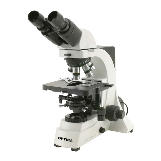
  • Seite 69: Beschreibung

    Beschreibung DIOPTIENVERSTELLUNGSRING OKULAR REVOLVER OBJEKTIV SPANNUNGVER- STELLUNGSRING TISCH KONDENSORZENTRIERUNGSKNOPF APERTURBLENDE FEINTRIEBDREHKNOPF FELDBLENDE VERSCHIEBUNGSKNOPF GROBTRIEBDREHKNOPF Pagina 69...
  • Seite 70: Auspacken

    Auspacken Das Mikroskop ist in einer Schachtel aus Styroporschicht enthalten. Entfernen Sie das Klebeband von der Schachtel und öffnen Sie mit Vorsicht den oberen Teil, ohne Objektive und Okulare zu beschädigen. Mit beiden Händen (eine um dem Stativ und eine um der Basis) ziehen Sie das Mikroskop aus der Schachtel heraus und stellen Sie es auf eine stabile Oberfläche.
  • Seite 71 Führen Sie beide Okulare in die Röhrenöffnungen ein. (Abbildung 2) Fig.2 Setzen Sie den Kondensor unter den Kreuztisch ein, so dass er sich in seiner Hal- terung befindet (unter dem Kondensor gibt es einen Bol- zen, der völlig in die Leitung des Kondensors eintreten muss).
  • Seite 72 Verbinden Sie den Netzteilka- bel an die Büchse an der Rückseite. (Abbildung 6) Fig.6 Pagina 72...
  • Seite 73: Verwendung Des Mikroskops

    Verwendung des Mikroskops LED EINSTELLUNGEN Um die Durchlitsbeleuchtung anzuschal- ten, verbinden Sie den Stecker von dem Netzteilkabel an die Büchse und schalten Sie den Hauptschalter an der Rückseite. Drehen Sie den Lichteinstellungsknopf, bis Sie die bestmögliche Lichteinstellung gefunden HAUPTSCHALTER haben (Abbildung 7). Fig.7 Einstellung des Kopfes Lockern Sie die Befesti-...
  • Seite 74: Dioptrienverstellung

    Fokusspannungsein- stellung Drehen Sie den Knopf für die Spannungseinstellung, um die bestmögliche Spannung zu erreichen. (Abbildung 11) HINWEIS: Ist die Span- nung zu locker, könnte der Kreuztisch herunterrutschen. In diesem Fall drehen Sie den Knopf, um die Spannung Fig.11 zu erhöhen. Scharfstellungsfesthal- tung Lockern Sie die Scharfstel- lungsfesthaltung, suchen Sie...
  • Seite 75: Einstellung Des Kondensors

    Einstellung des Kondensors Legen Sie die Swing-out Linse des Kondensors ① ein und schliessen Sie die Feldblende völlig ②. Drehen Sie den ④ Kondensorzentrierungsknob ③ bis ein scharfes Bild des ③ Lichtpunktes bei geschlosse- ner Feldblende zu sehen ist. ② Wirken Sie mit den Zentrie- Fig.14 ①...
  • Seite 76: Wartung

    Montieren Sie die Objektive und Okulare nicht ab, um sie zu reinigen. Am Besten verwenden Sie das OPTIKA Reinigungskit (siehe Katalog) Falls das Mikroskop aus Wartungszwecken an Optika zurückgeschickt werden muss, verwenden Sie bitte im- mer die Originalverpackung. Pagina 76...
  • Seite 77: Probleme Und Lösungen

    Probleme und Lösungen Siehe bitte die Tabelle hier unten für Lösungen an mögliche Probleme mit dem Mikroskop. PROBLEM URSACHE LÖSUNG 1. Optisches System Die LED beleuchtet nicht. Das Netzkabel ist nicht verbindet Das Netzkabel verbinden. Die LED funktioniert aber das Apertur- und Irisfeldblende sind nicht Beide Blenden verstellen.
  • Seite 78 PROBLEM URSACHE LÖSUNG Eine Seite des Bildes ist un- Das Objektiv ist in dem optischen Weg Vergewissern Sie sich, dass der Revolv- scharf. nicht korrekt zentriert. er in der korrekten Position ist. Der Revolver ist nicht richtig montiert. Vergewissern Sie sich, dass der Revolver in der korrekten Position ist.
  • Seite 79: Wiederverwertung

    Wiederverwertung Gemäß dem Artikel 13 vom Dekret Nr. 151 vom 25.07.2005 “Umsetzung der Richtlinien 2002/95/EG, 2002/96/EG und 2003/108/EG in Bezug auf die Verwendung gefährlicher Stoffe in elektrischen und elektronischen Geräten sowie die Abfallentsorgung” Das Symbol vom Müllcontainer erscheint auf dem Gerät oder der Verpackung und weist darauf hin, dass das Produkt Ende des Lebens separat von anderen Abfällen entsorgt werden muss.
  • Seite 80 OPTIKA S.r.l. ® Via Rigla, 30 - 24010 Ponteranica (BG) - ITALIA Tel.: +39 035.571.392 - Fax: +39 035.571.435 info@optikamicroscopes.com - www.optikamicroscopes.com OPTIKA Spain spain@optikamicroscopes.com OPTIKA USA usa@optikamicroscopes.com OPTIKA China china@optikamicroscopes.com OPTIKA Hungary hungary@optikamicroscopes.com OPTIKA India india@optikamicroscopes.com...

Inhaltsverzeichnis