Herunterladen Inhalt Inhalt Diese Seite drucken
Inhaltsverzeichnis

Werbung

Verfügbare Sprachen
  • DE

Verfügbare Sprachen

  • DEUTSCH, seite 18
Operating Instructions/Bedienungsanleitung/
Before operating this product, please read the instructions carefully and save this
manual for future use.
Bitte lesen Sie diese Bedienungsanleitung vor der Inbetriebnahme dieses Produkts
aufmerksam durch, und bewahren Sie sie für späteres Nachschlagen auf.
Avant d'utiliser l'appareil, lire attentivement ce mode d'emploi, et le conserver à
des fins de référence ultérieure.
Prima di far funzionare questo prodotto, leggere attentamente le istruzioni e
conservare questo manuale per riferimenti futuri.
Antes de utilizar este producto, lea cuidadosamente las instrucciones y guarde este
manual por si tiene que utilizarlo en el futuro.
このたびは、パナソニック製品をお買い上げいただき、まことにありがとうございます。
■ 取扱説明書をよくお読みのうえ、正しく安全にお使いください。
■ ご使用前に「安全上のご注意」 ( J-2 ~ J-3 ページ)を必ずお読みください。
■ 保 証書は「お買い上げ日・販売店名」などの記入を確かめ、取扱説明書とともに大切に保
管してください。
保証書別添付
製造番号は、品質管理上重要なものです。製品本体と保証書の製造番号をお確かめください。
FJ0812KT0 -FJ
Printed in Japan
Mode d'emploi/Istruzioni per l'uso/
Instrucciones de funcionamiento/
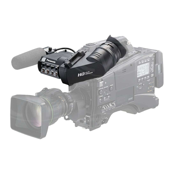
Electronic HD Color View Finder
Elektronischer HD-Farbe-Sucher
Viseur électronique HD couleur
Model No.
HD colore mirino elettronico
HD color visor electrónico
HD カラービューファインダー
AG-CVF10G
取扱説明書
VQT4L16

Werbung

Inhaltsverzeichnis
loading

Inhaltszusammenfassung für Panasonic AG-CVF10G

  • Seite 1 Viseur électronique HD couleur HD colore mirino elettronico HD color visor electrónico HD カラービューファインダー AG-CVF10G Model No. Before operating this product, please read the instructions carefully and save this manual for future use. Bitte lesen Sie diese Bedienungsanleitung vor der Inbetriebnahme dieses Produkts aufmerksam durch, und bewahren Sie sie für späteres Nachschlagen auf.
  • Seite 2: Read This First

    Read this first! For General WARNING: • To reduce the risk of fire, do not expose this equipment to rain or moisture. • To reduce the risk of fire, keep this equipment away from all liquids. Use and store only in locations which are not exposed to the risk of dripping or splashing liquids, and do not place any liquid containers on top of the equipment. CAUTION: Do not remove panel covers by unscrewing them. No user serviceable parts inside. Refer servicing to qualified service personnel. CAUTION: • Do not point the eyepiece directly at the sun. indicates safety information. EEE Yönetmeliğine Uygundur. EEE Complies with Directive of Turkey. The rating plate is on the underside of the unit.
  • Seite 3 Read this first! (continued) For USA This device complies with part 15 of the FCC Rules. Operation is subject to the following two conditions: (1) This device may not cause harmful interference, and (2) this device must accept any interference received, including interference that may cause undesired operation. FCC Note: This equipment has been tested and found to comply with the limits for a class B digital device, pursuant to Part 15 of the FCC Rules. These limits are designed to provide reasonable protection against harmful interference in a residential installation. This equipment generates, uses, and can radiate radio frequency energy and, if not installed and used in accordance with the instruction manual, may cause harmful interference to radio communications. However, there is no guarantee that interference will not occur in a particular installation. If this equipment does cause harmful interference to radio or television reception, which can be determined by turning the equipment off and on, the user is encouraged to try to correct the interference by one or more of the following measures: • Reorient or relocate the receiving antenna. • Increase the separation between the equipment and receiver. • Connect the equipment into an outlet on a circuit different from that to which the receiver is connected. • Consult the dealer or an experienced radio/TV technician for help. • The user may find the booklet “Something About Interference” available from FCC local regional offices helpful. Warning: To assure continued FCC emission limit compliance, the user must use only shielded interface cables when connecting to external units. Also, any unauthorized changes or modifications to this equipment could void the user’s authority to operate it. For Canada NOTIFICATION (Canada) This class B digital apparatus complies with Canadian ICES-003. indicates safety information.
  • Seite 4 Read this first! (continued) EMC NOTICE FOR THE PURCHASER/USER OF THE APPARATUS 1. Applicable standards and operating environment The apparatus is compliant with: • s tandards EN55103-1 and EN55103-2 2009, and • electromagnetic environments E1, E2, E3 and E4. 2. Pre-requisite conditions to achieving compliance with the above standards <1> Peripheral equipment to be connected to the apparatus and special connecting cables •...
  • Seite 5: Inhaltsverzeichnis

    Table of contents Read this first! ..........................E-1 Operating precautions ........................E-5 Accessory ............................E-5 Features............................E-5 Parts and their functions ......................E-6 Adjusting the viewfinder ....................... E-8 Attaching the viewfinder....................... E-8 Adjusting the viewfinder’s left-right position ................. E-9 Adjusting the viewfinder’s front-back position (for a camera featuring a front-back position adjustment slider) ..........E-9 Detaching the viewfinder ......................E-10 Adjusting the angle of the viewfinder ..................E-11 Flipping up the viewfinder barrel unit .
  • Seite 6: Operating Precautions

    Operating precautions Compatible camera recorders This viewfinder supports the AG-HPX600 and AJ-HPX series of camera recorders. Please contact the dealers for other compatible models. Depending on the model, viewfinder output may be set to black and white image as an initial setting. For how to switch the output to a color image, refer to the operating instructions for each camera recorder. Concerning a monitor with a liquid crystal display • When the same images or characters are left displayed for prolonged periods of time on an LCD monitor, image burn-in may occur on the screen. However, the screen will revert to normal once the power has been turned off and kept turned off for several hours. • The ratio of effective pixels used for the LCD monitor is controlled to the high accuracy of more than 99.99%, which means that less than 0.01% of the pixels may be missing or permanently lighted. This is not indicative of any malfunctioning and does not have any adverse effect on the recorded images. • Condensation may form on the LCD monitor in locations where the temperature fluctuates significantly. If condensation does form, wipe it off using a soft dry cloth. • If the viewfinder unit has become cold, the images displayed on the LCD monitor will be slightly darker than usual immediately after the power is turned on. The normal brightness will be restored once the temperature inside rises. Accessory The following accessory is attached to the viewfinder. • Eye cup Features • Focusing is now easier thanks to the use of a high-definition color LCD monitor. • The viewfinder barrel unit can be flipped up, and operations can then be performed while directly viewing the LCD monitor with its large screen. • This viewfinder can replace an existing HD viewfinder. • The viewfinder can be used with the AG-HPX600 and AJ-HPX series.
  • Seite 7: Parts And Their Functions

    Parts and their functions               PEAKING CHROMA CONTRAST BRIGHT MIRROR B.LIGHT ZEBRA TALLY HIGH HIGH        1 PEAKING control Adjusts the outlines of the images in the viewfinder to make focusing easier. The setting of this control has no effect on the output signal of the camera. The amount of the adjustment is increased when the control is rotated clockwise.
  • Seite 8 Parts and their functions (continued) 7 ZEBRA switch Displays a zebra pattern inside the viewfinder. : Displays a zebra pattern. OFF : No zebra pattern is displayed. The details of the display, such as the type of zebra pattern, will differ depending on the camera used with the viewfinder. Refer to the instruction manual of the camera for details. 8 TALLY switch Controls the front tally lamp. HIGH : M akes the front tally lamp brighter. OFF : Turns the tally lamp off. LOW : Makes the front tally lamp dimmer. 9 Slide stopper (Screw-in type) Prevents the viewfinder from becoming detached from the camera when it is attached and slid to the left or right. This is a screw-in type of slide stopper.  Slide rail Slide rail for installing to the camera unit.
  • Seite 9: Adjusting The Viewfinder

    Adjusting the viewfinder Attaching the viewfinder Confirm that the POWER switch of the camera is “OFF”. Connect the plug of the connecting cable to the VF connector on the camera. Note When connecting the plug of the connecting cable to the VF connector on the camera, push it firmly in all the way. Viewfinder left-right position anchoring ring Loosen the ring. Loosen the viewfinder left-right position anchoring ring of the camera. Loosen the screw of the slide stopper, and then attach the viewfinder by sliding it in the direction of the arrow. After attaching the viewfinder, tighten the screw of the slide stopper. Slide stopper Tighten the ring. Tighten the screw of the slide stopper. Tighten the viewfinder left-right position anchoring ring of the camera.
  • Seite 10: Adjusting The Viewfinder's Left-Right Position

    Adjusting the viewfinder (continued) Adjusting the viewfinder’s left-right position Loosen the viewfinder left-right position anchoring ring. Slide the viewfinder to the left or right, and adjust it to a position that allows easy viewing. Tighten the ring. Viewfinder left-right position anchoring ring Tighten the viewfinder left-right position anchoring ring. Adjusting the viewfinder’s front-back position (for a camera featuring a front-back position adjustment slider) Loosen the viewfinder front-back position anchoring lever. Slide the viewfinder to the front or back, and adjust it to a position that allows easy viewing. Viewfinder front-back position anchoring lever Loosen the viewfinder front-back Loosen the viewfinder front-back...
  • Seite 11: Detaching The Viewfinder

    Adjusting the viewfinder (continued) Detaching the viewfinder Confirm that the POWER switch of the camera is “OFF”. Loosen the viewfinder left-right position anchoring ring of the camera. Loosen the screw of the slide stopper, and then remove the viewfinder by sliding it in the direction of the arrow. Loosen the ring. Slide stopper Loosen the screw of the slide stopper. Release the viewfinder cable and mic cable from the cable clamps, and disconnect the cables. E-10...
  • Seite 12: Adjusting The Angle Of The Viewfinder

    Adjusting the viewfinder (continued) Adjusting the angle of the viewfinder The angle of the viewfinder barrel unit can be adjusted in a range from 0 ° to 300 ° as shown in the figure below. Adjust it to the angle that assures the best viewing. Rotated 300 ° • Rotate the viewfinder barrel unit toward the subject side, and the images and character displays can then be inverted vertically so that the images can be seen from the subject side. In cases like this, the normal images can be displayed by setting the MIRROR switch on the viewfinder’s rear panel to B/T. (Page 6) Flipping up the viewfinder barrel unit The lock lever can be slid to flip up the viewfinder barrel unit and perform operations while viewing the LCD monitor directly. Lock lever • If the MIRROR switch on the viewfinder’s rear panel is set to L/R when performing operations while viewing the LCD monitor directly after flipping up the viewfinder barrel unit, the image can be left/right reversed so that normal images are seen. (Page 6) Note If there is any dirt on the mirror, remove it referring to “Detaching the eyepiece and performing maintenance”. (Page 13) E-11...
  • Seite 13: Diopter Adjustment

    Adjusting the viewfinder (continued) Diopter adjustment Set the POWER switch of the camera to “ON”. A picture will appear in the viewfinder. Turn the diopter adjustment ring to adjust the diopter so that the viewfinder picture can be clearly seen. Diopter adjustment ring • Diopter adjustment range: –3.7 D to +1.1 D Screen adjustment Adjust the condition of the viewfinder screen. (Page 6) Brightness : Adjust the BRIGHT control. Contrast : Adjust the CONTRAST control. Chroma : Adjust the CHROMA control. Contour : Adjust the PEAKING control. PEAKING CHROMA CONTRAST BRIGHT MIRROR B.LIGHT ZEBRA TALLY HIGH HIGH PEAKING control CHROMA control CONTRAST control...
  • Seite 14: Detaching The Eyepiece And Performing Maintenance

    Detaching the eyepiece and performing maintenance It is easier to see the whole screen if the eyepiece is detached at times when you want to look up or away from the viewfinder and take shots. Also, detach the eyepiece if there is any dirt on the mirror so that the dirt can be removed. Note When there is any dirt on the mirror, blow it away with a blower, etc. If any dirt is still left, wipe it away using a soft cloth. Turn the lock ring as far as it will go in Eyepiece the counterclockwise direction as seen Alignment marks from the eyepiece side, and line up the alignment marks on the lock ring and viewfinder barrel. Lock ring Detach the eyepiece. Remounting the eyepiece Line up the alignment marks on the lock ring and the viewfinder barrel and slide the eyepiece back into place. Turn the lock ring clockwise as far as the position. Notes • Do not leave the eyepiece outdoors pointing at the sun. Heat from the sunlight may damage the parts inside. • Take care not to lose or misplace the eyepiece after it has been removed. E-13...
  • Seite 15: Attaching The Microphone

    Attaching the microphone The AG-MC200G XLR microphone (optional accessory) can be attached. Open the microphone holder. Viewfinder Microphone holder Attach the microphone. Plug the microphone connector cable into the MIC IN jack. MIC IN jack E-14...
  • Seite 16: Specifications

    Specifications Power supply: DC 12 V (supplied by camera) Power consumption: 2.8 W indicates safety information. Display panel: 87.63 mm (3.45-inch) wide LCD color monitor (approx. 920,000 dots) Image system: 1080/50i,1080/59.94i External adjustment controls: Controls PEAKING CHROMA CONTRAST BRIGHT Switches MIRROR (L/R, OFF, B/T) B.LIGHT (HIGH, NOR, LOW) ZEBRA (ON, OFF) TALLY (HIGH, OFF, LOW) Ambient operating temperature: 0 °C to 40 °C (32 °F to 104 °F) Ambient operating humidity: 10% to 85% (no condensation) Storage temperature: –20 °C to 60 °C (–4 °F to 140 °F)
  • Seite 17 Information on Disposal for Users of Waste Electrical & Electronic Equipment (private households) This symbol on the products and/or accompanying documents means that used electrical and electronic products should not be mixed with general household waste. For proper treatment, recovery and recycling, please take these products to designated collection points, where they will be accepted on a free of charge basis. Alternatively, in some countries you may be able to return your products to your local retailer upon the purchase of an equivalent new product. Disposing of this product correctly will help to save valuable resources and prevent any potential negative effects on human health and the environment which could otherwise arise from inappropriate waste handling. Please contact your local authority for further details of your nearest designated collection point.
  • Seite 18 Bitte lesen! WARNUNG: • Zur Reduzierung der Gefahr eines Brands dieses Gerät weder Nässe noch Feuchtigkeit aussetzen. • Zur Reduzierung der Gefahr eines Brands muss dieses Gerät von allen Flüssigkeiten ferngehalten werden. Vermeiden Sie Gebrauch und Lagerung des Gerätes an orten, an denen die Gefahr besteht, dass es mit Flüssigkeiten betropft oder bespritzt wird, und stellen Sie keine Flüssigkeitsbehälter auf das Gerät. VORSICHT: Öffnen Sie nicht das Gerät durch Abschrauben von Gehäuseteilen. Im Geräteinneren befinden sich keine Teile, die vom Benutzer gewartet werden können. Wartungs- und Reparaturarbeiten grundsätzlich autorisiertem Kundendienstpersonal überlassen. VORSICHT: • Richten Sie das Okular nicht direkt auf die Sonne. ist die Sicherheitsinformation. Das Typenschild befindet sich auf der Unterseite des Gerätes.
  • Seite 19: Emv-Hinweis Für Den Käufer/Anwender Des Geräts

    Bitte lesen! (Fortsetzung) EMV-HINWEIS FÜR DEN KÄUFER/ANWENDER DES GERÄTS 1. Anwendbare Standards und Betriebsumgebung Dieses Gerät entspricht: • S tandards EN55103-1 und EN55103-2 2009 und • elektromagnetische Umgebungen, E1, E2, E3 und E4. 2. Erforderliche Bedingungen zur Einhaltung der oben genannten Standards <1> An das Gerät angeschlossene Geräte und spezielle Verbindungskabel •...
  • Seite 20 Inhalt Bitte lesen! .............................G-1 Vorsichtshinweise zum Betrieb ....................G-4 Zubehör ............................G-4 Merkmale ............................G-4 Teile und ihre Funktionen ......................G-5 Einstellen des Suchers .........................G-7 Anbringen des Suchers .......................G-7 Einstellen der Querposition des Suchers ..................G-8 Einstellen der Längsposition des Suchers (für eine Kamera mit Längsposition-Einstellschieber) ..............G-8 Abnehmen des Suchers ......................G-9 Einstellen des Sucherwinkels ....................G-10 Hochklappen der Suchertubus-Einheit ..................G-10 Dioptrieneinstellung ........................G-11 Sucherschirmeinstellung......................G-11 Abnehmen des Okulars und Durchführen von Wartungsarbeiten ......... G-12 Anbringen des Mikrofons ......................G-13 Technische Daten ........................G-14 Hinweis zu den Abbildungen in dieser Anleitung...
  • Seite 21: Vorsichtshinweise Zum Betrieb

    Vorsichtshinweise zum Betrieb Kompatible Kamerarecorder Dieser Sucher unterstützt die Kamerarecorder AG-HPX600 und die der Serie AJ-HPX. Bitte kontaktieren Sie die Händler, wenn Sie sich für andere kompatible Modelle interessieren. Je nach dem Modell ist die Sucherausgabe eventuell auf Schwarzweiß als Anfangseinstellung eingestellt. Wie man die Ausgabe auf Farbbild umstellt, finden Sie in der Betriebsanleitung des jeweiligen Kamerarecorders. Bezüglich eines Monitors mit Flüssigkristalldisplay • Bleiben dieselben Bilder oder Zeichen für längere Zeitspannen auf einem LCD-Monitor angezeigt, kann es zum Einbrennen des Bilds auf dem Bildschirm kommen. Der Bildschirm kehrt jedoch wieder zum Normalzustand zurück, nachdem die Stromversorgung ausgeschaltet worden ist und mehrere Stunden lang ausgeschaltet bleibt. • Der Anteil der effektiven Bildpunkte des LCD-Monitors erreicht einen hohen Wert von über 99,99%, was bedeutet, dass die Wahrscheinlichkeit von fehlenden oder ständig leuchtenden Bildpunkten weniger als 0,01% beträgt. Dies ist kein Anzeichen für eine Funktionsstörung und hat keine negative Auswirkung auf die aufgezeichneten Bilder. • An Orten, die erheblichen Temperaturschwankungen unterliegen, kann sich Kondensation auf dem LCD-Monitor bilden. Falls Kondensation sich bildet, wischen Sie die Feuchtigkeit mit einem weichen, trockenen Tuch ab. • Falls die Suchereinheit kalt geworden ist, erscheinen die auf dem LCD-Monitor angezeigten Bilder unmittelbar nach dem Einschalten etwas dunkler als gewöhnlich. Die normale Helligkeit wird wiederhergestellt, sobald die Innentemperatur steigt. Zubehör Das folgende Zubehör ist am Sucher angebracht. • Augenmuschel Merkmale • Dank der Verwendung eines High-Definition-Farb-LCD-Monitors ist die Fokussierung nun leichter. • Die Suchertubus-Einheit kann hochgeklappt werden, und Bedienungsvorgänge können dann bei direkter Betrachtung des großen LCD-Monitorschirms durchgeführt werden. • Dieser Sucher kann einen vorhandenen HD-Sucher ersetzen. • Der Sucher kann mit den Geräten AG-HPX600 und denen der Serie AJ-HPX verwendet werden.
  • Seite 22: Teile Und Ihre Funktionen

    Teile und ihre Funktionen               PEAKING CHROMA CONTRAST BRIGHT MIRROR B.LIGHT ZEBRA TALLY HIGH HIGH        1 Regler PEAKING Dient zur Einstellung der Bildkonturen im Sucher, um die Scharfeinstellung zu erleichtern. Die Einstellung dieses Reglers hat keinen Einfluß auf das Ausgangssignal der Kamera. Durch Drehen des Reglers im Uhrzeigersinn wird der Einstellungsbetrag erhöht.
  • Seite 23 Teile und ihre Funktionen (Fortsetzung) 6 Schalter B.LIGHT Dient der Einstellung der Hintergrundbeleuchtung des LCD-Monitors. HIGH D ie Hintergrundbeleuchtung ist heller als normal. D ie Hintergrundbeleuchtung ist auf die normale Helligkeit eingestellt. : D ie Hintergrundbeleuchtung ist dunkler als normal. 7 Zebramusterschalter [ZEBRA] Dient zum Anzeigen eines Zebramusters im Sucher. ON : Ein Zebramuster wird angezeigt. OFF : Kein Zebramuster wird angezeigt. Die Details der Anzeige, z.B. die Art des Zebramusters, hängen von der mit dem Sucher verwendeten Kamera ab. Einzelheiten sind der Bedienungsanleitung der Kamera zu entnehmen. 8 Signallampenschalter [TALLY] Steuert die vordere Signallampe. HIGH : E rhöht die Helligkeit der vorderen Signallampe. OFF : Schaltet die Signallampe aus. LOW : Verringert die Helligkeit der vorderen Signallampe.
  • Seite 24: Einstellen Des Suchers

    Einstellen des Suchers Anbringen des Suchers Sicherstellen, daß sich der Schalter POWER der Kamera in der AUS-Stellung befindet. Schließen Sie den Stecker des Verbindungskabels an den Sucheranschluss der Kamera an. Hinweis Schieben Sie den Stecker des Verbindungskabels beim Anschließen an den Sucheranschluss der Kamera bis zum Anschlag ein. Querpositions-Feststellring des Suchers Den Ring lösen. Lösen Sie den Querpositions-Feststellring des Suchers der Kamera. Bringen Sie den Sucher durch Einschieben in Pfeilrichtung an, während Sie den Gleitanschlag hochziehen. Vergewissern Sie sich nach der Anbringung des Suchers, dass der Anschlag in der korrekten Position ist. Gleitanschlag Den Ring anziehen. Die Schraube des Gleitan- schlags anziehen. Ziehen Sie den Querpositions-Feststellring des Suchers der Kamera an.
  • Seite 25: Einstellen Der Querposition Des Suchers

    Einstellen des Suchers (Fortsetzung) Einstellen der Querposition des Suchers Lösen Sie den Querpositions-Feststellring des Suchers. Schieben Sie den Sucher nach links oder rechts, um seine Position so einzustellen, dass der Suchermonitor bequem ablesbar ist. Den Ring anziehen. Querpositions-Feststellring des Suchers Ziehen Sie den Querpositions-Feststellring des Suchers an. Einstellen der Längsposition des Suchers (für eine Kamera mit Längsposition-Einstellschieber) Lösen Sie den Längspositions-Feststellhebel des Suchers. Schieben Sie den Sucher nach vorn oder hinten, um seine Position so einzustellen, dass der Suchermonitor bequem ablesbar ist. Längspositions-Feststellhebel des Suchers Lösen Sie den Längspositions- Lösen Sie den Längspositions- Feststellhebel des Suchers.
  • Seite 26: Abnehmen Des Suchers

    Einstellen des Suchers (Fortsetzung) Abnehmen des Suchers Sicherstellen, daß sich der Schalter POWER der Kamera in der AUS-Stellung befindet. Lösen Sie den Querpositions-Feststellring des Suchers der Kamera. Lösen Sie die Schraube des Gleitanschlags, und entfernen Sie dann den Sucher durch Schieben in Pfeilrichtung. Den Ring lösen. Gleitanschlag Die Schraube des Gleit- anschlags lösen. Lösen Sie das Sucherkabel und das Mikrofonkabel aus den Kabelklemmen, und trennen Sie die Kabel ab.
  • Seite 27: Einstellen Des Sucherwinkels

    Einstellen des Suchers (Fortsetzung) Einstellen des Sucherwinkels Der Winkel der Suchertubus-Einheit kann innerhalb eines Bereichs von 0 ° bis 300 ° eingestellt werden, wie in der nachstehenden Abbildung dargestellt. Stellen Sie den Sucher auf einen Winkel ein, der optimalen Einblick gewährleistet. Um 300 ° gedreht • Wird die Suchertubus-Einheit zur Motivseite gedreht, können die Bilder und Zeichenanzeigen vertikal invertiert werden, so dass die Bilder von der Motivseite aus betrachtet werden können. In solchen Fällen können die normalen Bilder angezeigt werden, indem der Schalter MIRROR an der Rückseite des Suchers auf B/T gestellt wird. (Seite 5) Hochklappen der Suchertubus-Einheit Der Verriegelungshebel kann verschoben werden, um die Suchertubus-Einheit zur direkten Betrachtung des LCD-Monitors hochzuklappen. Verriegelungshebel • Wird der Schalter MIRROR auf der Rückseite des Suchers auf L/R gestellt, um Bedienungsvorgänge bei direkter Betrachtung des LCD-Monitors nach dem Hochklappen der Suchertubus-Einheit durchzuführen, kann das Bild horizontal gedreht werden, so dass normale Bilder angezeigt werden. (Seite 5) Hinweis Falls Schmutz am Spiegel haftet, entfernen Sie ihn gemäß den Angaben unter „Abnehmen des Okulars und Durchführen von Wartungsarbeiten“. (Seite 12) G-10...
  • Seite 28: Dioptrieneinstellung

    Einstellen des Suchers (Fortsetzung) Dioptrieneinstellung Den Schalter POWER der Kamera auf die EIN-Stellung stellen. Ein Bild erscheint im Sucher. Das Okular durch Drehen des Dioptrien-Einstellrings so einstellen, daß das Sucherbild scharf ist. Dioptrien-Einstellring • Dioptrien-Einstellbereich : –3,7 D bis +1,1 D Sucherschirmeinstellung Den Zustand des Sucherschirms einstellen. (Seite 5) Helligkeit : Den Regler BRIGHT drehen. Kontrast : Den Regler CONTRAST drehen. Sättigung : Den Regler CHROMA drehen. Kontur : Den Regler PEAKING drehen. PEAKING CHROMA CONTRAST BRIGHT MIRROR B.LIGHT ZEBRA TALLY HIGH HIGH Regler PEAKING Regler CHROMA Regler CONTRAST Regler BRIGHT Den Schalter POWER der Kamera auf die EIN-Stellung stellen.
  • Seite 29: Abnehmen Des Okulars Und Durchführen Von Wartungsarbeiten

    Abnehmen des Okulars und Durchführen von Wartungsarbeiten Wenn Sie zur Durchführung von Aufnahmen vom Sucher aufblicken oder wegblicken wollen, können Sie den ganzen Bildschirm besser sehen, indem Sie das Okular abnehmen. Nehmen Sie das Okular auch ab, falls Schmutz am Spiegel haftet, um diesen zu reinigen. Hinweis Falls Schmutz am Spiegel haftet, blasen Sie ihn mit einem Blasepinsel o. Ä. weg. Ist noch immer Schmutz vorhanden, wischen Sie ihn mit einem weichen Tuch weg. Drehen Sie den Verriegelungsring Okular bis zum Anschlag entgegen dem Ausrichtmarkierungen Uhrzeigersinn, von der Okularseite aus gesehen, und richten Sie die Ausrichtmarkierungen an Verriegelungs- Verriegelungsring und Suchertubus ring aufeinander aus. Das Okular abnehmen. Anbringen des Okulars Die Ausrichtmarkierungen an Verriegelungsring und Suchertubus zur Deckung bringen, und das Okular wieder einschieben. Den Verriegelungsring bis zur Position nach rechts drehen. Hinweise • Lassen Sie das Okular nicht im Freien auf die Sonne gerichtet liegen. Die Wärme des Sonnenlichts kann die Innenteile beschädigen. • Achten Sie darauf, dass das Okular nach dem Abnehmen nicht verloren geht oder verlegt wird. G-12...
  • Seite 30: Anbringen Des Mikrofons

    Anbringen des Mikrofons Das XLR-Mikrofon AG-MC200G (Sonderzubehör) kann angebracht werden. Den Mikrofonhalter öffnen. Sucher Mikrofonhalter Das Mikrofon anbringen. Den Stecker des Mikrofonkabels an die Buchse MIC IN anschließen. Buchse MIC IN G-13...
  • Seite 31: Technische Daten

    Technische Daten Stromversorgung 12 V Gleichspannung (Versorgung durch Kamera) Leistungsaufnahme : 2,8 W ist die Sicherheitsinformation. Anzeige: 87,63 mm (3,45-Typ) breiter LCD-Farbmonitor (ca. 920.000 Punkte) Bildsystem: 1080/50i,1080/59,94i Externe Regler und Schalter: Regler PEAKING CHROMA CONTRAST BRIGHT Schalter MIRROR (L/R, OFF, B/T) B.LIGHT (HIGH, NOR, LOW) ZEBRA (ON, OFF) TALLY (HIGH, OFF, LOW) Betriebstemperatur: 0 °C bis 40 °C Betriebsluftfeuchtigkeit: 10% bis 85% (keine Kondensation) Lagertemperatur: –20 °C bis 60 °C Außenabmessungen (B  H  T): 248 mm  77 mm  216 mm Gewicht: ca. 600 g G-14...
  • Seite 32 Benutzerinformationen zur Entsorgung von elektrischen und elektronischen Geräten (private Haushalte) Dieses Symbol auf Produkten und/oder begleitenden Dokumenten bedeutet, dass verbrauchte elektrische und elektronische Produkte nicht mit gewöhnlichem Haushaltsabfall vermischt werden sollen. Bringen Sie zur ordnungsgemäßen Behandlung, Rückgewinnung und Recycling diese Produkte zu den entsprechenden Sammelstellen, wo sie ohne Gebühren entgegengenommen werden. In einigen Ländern kann es auch möglich sein, diese Produkte beim Kauf eines entsprechenden neuen Produkts bei Ihrem örtlichen Einzelhändler abzugeben.
  • Seite 33: Lire Ces Informations En Premier

    Lire ces informations en premier ! Pour le général AVERTISSEMENT: • Pour réduire tout risque d’incendie, évitez d’exposer cet appareil à la pluie ou à l’humidité. • Pour réduire tout risque d’incendie, éloignez l’appareil des liquides. Utiliser et ranger uniquement dans un endroit ne risquant pas de recevoir des gouttes ou d’être aspergé de liquides, et ne pas mettre de récipient renfermant des liquides sur le dessus de l’appareil. ATTENTION: Ne pas dévisser le couvercle. Il ne se trouve à l’intérieur aucune pièce qui puisse être réparée par l’utilisateur. Confier toute réparation à un personnel qualifié. ATTENTION: • Veiller à ne pas diriger l’oculaire directement sur le soleil. Pour le Canada NOTIFICATION (Canada) Cet appareil numéique de la classe B est conforme à la norme NMB-003 du Canada. Informations concernant la sécurité. La plaque signalétique est située sous l’appareil.
  • Seite 34 Lire ces informations en premier ! (suite) NOTE D’INFORMATION SUR LA CEM POUR L’ACHETEUR/ UTILISATEUR DE L’APPAREIL 1. Normes applicables et environnement de fonctionnement L’appareil est conforme: • a ux normes EN55103-1 et EN55103-2 2009, et • aux environnements électromagnétiques E1, E2, E3 et E4. 2. Conditions requises pour obtenir la conformité aux normes ci-dessus <1>...
  • Seite 35 Table des matières Lire ces informations en premier !....................F-1 Précautions à prendre pour l’utilisation ..................F-4 Accessoire ............................F-4 Caractéristiques ..........................F-4 Les commandes et leurs fonctions ....................F-5 Réglage du viseur...........................F-7 Montage du viseur ........................F-7 Réglage de la position gauche-droite du viseur ................F-8 Réglage de la position avant-arrière du viseur (pour une caméra munie d’un curseur de réglage de la position avant-arrière) ......F-8 Retrait du viseur..........................F-9 Réglage de l’angle du viseur ......................F-10 Relèvement du barillet du viseur ....................F-10 Réglage de la correction dioptrique ....................F-11 Réglage de l’écran .
  • Seite 36: Précautions À Prendre Pour L'utilisation

    Précautions à prendre pour l’utilisation Caméscopes compatibles Ce viseur est compatible avec les caméscopes AG-HPX600 et ceux de la série AJ-HPX. Veuillez contacter le revendeur pour les autres modèles compatibles. Suivant le modèle, le réglage initial de la sortie du viseur peut être une image noir et blanc. Pour connaitre la façon de changer la sortie sur une image couleur, référez-vous aux consignes d’utilisation pour chaque caméscope. Précisions concernant le moniteur avec écran à cristaux liquides • Si la même image ou les mêmes caractères sont laissés affichés pendant longtemps sur un moniteur LCD, une image rémanente risque d’apparaître sur l’écran. Cependant, l’écran revient à l’état normal si le moniteur est mis hors tension et laissé éteint pendant quelques heures. • La proportion de pixels efficaces sur le moniteur LCD atteint une précision élevée de 99,99%. Cela signifie que moins de 0,01% des pixels peuvent manquer ou rester allumés en permanence. Cela ne signifie pas un fonctionnement défectueux et n’a pas d’effet négatif sur les images enregistrées. • De la condensation peut se former sur le moniteur LCD quand il est utilisé dans un endroit avec des écarts de température importants. Si de la condensation se forme, l’essuyer avec un chiffon doux et sec. • Si le viseur est froid, les images affichées sur le moniteur LCD paraissent plus sombres que la normale immédiatement après la mise sous tension. La luminosité redevient normale quand la température interne augmente. Accessoire L’accessoire suivant est fixé au viseur. • Œilleton Caractéristiques • La mise au point est facilitée par l’utilisation d’un moniteur LCD couleur haute définition. • Le barillet du viseur peut être relevé, et il est possible d’effectuer la prise de vues en regardant directement le grand écran du moniteur LCD. • Ce viseur peut remplacer un viseur HD existant. • Ce viseur peut être utilisé avec les AG-HPX600 et la série AJ-HPX.
  • Seite 37: Les Commandes Et Leurs Fonctions

    Les commandes et leurs fonctions               PEAKING CHROMA CONTRAST BRIGHT MIRROR B.LIGHT ZEBRA TALLY HIGH HIGH        1 Commande PEAKING Elle permet de régler les contours de l’image dans le viseur de façon à les rendre plus nets. Le réglage de cette commande est sans effet sur le signal de sortie de la caméra. Tourner cette commande dans le sens des aiguilles d’une montre pour augmenter la quantité de réglage.
  • Seite 38 Les commandes et leurs fonctions (suite) 6 Commutateur de rétroéclairage (B.LIGHT) Il sert à régler la luminosité du rétroéclairage du moniteur LCD. HIGH : L e rétroéclairage est plus lumineux que la normale. NOR : L e rétroéclairage est réglé sur une luminosité normale. LOW : L e rétroéclairage est plus sombre que la normale. 7 Commutateur de motif de zébrures (ZEBRA) Il permet d’afficher un motif de zébrures dans le viseur. : Affiche un motif de zébrures. OFF : N’affichage pas de motif de zébrures. Les détails de l’affichage, comme le type du motif de zébrures, varient en fonction de la caméra utilisée.
  • Seite 39: Réglage Du Viseur

    Réglage du viseur Montage du viseur Vérifier que l’interrupteur POWER de la caméra est éteint (“OFF”). Raccorder la fiche du câble de connexion au connecteur VF de la caméra. Remarque La fiche du câble de connexion doit être insérée à fond dans le connecteur VF de la caméra. Bague d’ancrage de la position gauche-droite du viseur Desserrer la bague. Desserrer la bague d’ancrage de la position gauche-droite du viseur de la caméra. Desserrer la vis de la butée de rail, puis mettre le viseur en place en le faisant glisser dans le sens de la flèche. Une fois que le viseur est en place, serrer la vis de la butée de rail. Butée de rail Serrer la vis de la Serrer la bague. butée de rail. Serrer la bague d’ancrage de la position gauche-droite du viseur de la caméra.
  • Seite 40: Réglage De La Position Gauche-Droite Du Viseur

    Réglage du viseur (suite) Réglage de la position gauche-droite du viseur Desserrer la bague d’ancrage de la position gauche-droite du viseur. Glisser le viseur vers la gauche ou vers la droite, et le régler sur la position permettant une vue facile des données sur l’écran. Serrer la bague. Bague d’ancrage de la position gauche-droite du viseur Serrer la bague d’ancrage de la position gauche-droite du viseur. Réglage de la position avant-arrière du viseur (pour une caméra munie d’un curseur de réglage de la position avant-arrière) Desserrer le levier d’ancrage de la position avant-arrière du viseur.
  • Seite 41: Retrait Du Viseur

    Réglage du viseur (suite) Retrait du viseur Vérifier que l’interrupteur POWER de la caméra est éteint (“OFF”). Desserrer la bague d’ancrage de la position gauche-droite du viseur de la caméra. Desserrer la vis de la butée de rail, puis retirer le viseur en le faisant glisser dans le sens de la flèche. Desserrer la bague. Butée de rail Desserrer la vis de la butée de rail. Dégager le câble du viseur et le câble du microphone des colliers de câble, et débrancher les câbles.
  • Seite 42: Réglage De L'angle Du Viseur

    Réglage du viseur (suite) Réglage de l’angle du viseur L’angle du barillet du viseur peut être réglé dans une plage allant de 0 ° à 300 ° comme illustré ci-dessous. Le régler à l’angle offrant la meilleure vue. Rotation de 300 ° • Tourner le barillet du viseur vers le sujet. Les images et les affichages de caractères peuvent alors être retournés verticalement et les images peuvent être vues du côté du sujet. Dans de tels cas, les images normales peuvent être affichées. Régler le commutateur MIRROR situé sur le panneau arrière du viseur sur B/T. (Page 5) Relèvement du barillet du viseur Pousser le levier de verrouillage pour relever le barillet du viseur et effectuer des manipulations tout en regardant directement le moniteur LCD. Levier de verrouillage • Quand le barillet du viseur est relevé et que vous effectuez des manipulations en regardant directement le moniteur LCD, vous pouvez régler le commutateur MIRROR, situé sur le panneau arrière du viseur, sur L/R. L’image est alors inversée et vous pouvez voir des images normales. (Page 5) Remarque En cas de poussières sur le miroir, le déposer en se référant à « Dépose de l’oculaire et maintenance ». (Page 12) F-10...
  • Seite 43: Réglage De La Correction Dioptrique

    Réglage du viseur (suite) Réglage de la correction dioptrique Mettre l’interrupteur POWER de la caméra sur “ON”. Une image apparaît dans le viseur. Tourner la bague de correction dioptrique de façon que l’image du viseur soit nette. Bague de correction dioptrique • Plage de réglage dioptrique : –3,7 D à +1,1 D Réglage de l’écran Régler les conditions de l’écran du viseur. (Page 5) Luminosité : Régler la commande BRIGHT. Contraste : Régler la commande CONTRAST. Saturation : Régler la commande CHROMA. Contours : Régler la commande PEAKING. PEAKING CHROMA CONTRAST BRIGHT MIRROR B.LIGHT ZEBRA TALLY HIGH...
  • Seite 44: Dépose De L'oculaire Et Maintenance

    Dépose de l’oculaire et maintenance Le fait de retirer l’oculaire permet de bien voir l’écran entièrement, ce qui est pratique quand vous voulez filmer en regardant au-dessus du viseur. Par ailleurs, en cas de poussières sur le miroir, déposer l’oculaire pour pouvoir le nettoyer. Remarque S’il y a de la poussière sur le miroir, le dépoussiérer à l’aide d’une poire soufflante, ou autre. S’il est encore sale, essuyer le miroir à l’aide d’un chiffon doux. Tourner la bague de verrouillage à fond Oculaire dans le sens contraire des aiguilles Repères d’alignement d’une montre vu depuis l’oculaire, et aligner les repères d’alignement sur la bague de verrouillage et le barillet du Bague de viseur. verrouillage Retirer l’oculaire. Remontage de l’oculaire Amener les repères d’alignement de la bague de verrouillage sur ceux du barillet du viseur, et glisser l’oculaire pour le remettre en place. Tourner la bague de verrouillage vers la droite jusqu’à la position Remarques • Ne pas laisser l’oculaire sorti pointé vers le soleil. La chaleur du soleil pourrait endommager les pièces internes. • Prendre garde de ne pas perdre ou mal ranger l’oculaire après sa dépose. F-12...
  • Seite 45: Montage Du Microphone

    Montage du microphone Le microphone XLR AG-MC200G (accessoire optionnel) peut être installé. Ouvrir le support de microphone. Viseur Support de microphone Monter le microphone. Brancher le câble de raccordement du microphone dans la prise MIC IN. Prise MIC IN F-13...
  • Seite 46: Fiche Technique

    Fiche technique Alimentation CC 12 V (fournie par la caméra) Consommation : 2,8 W Informations concernant la sécurité. Panneau d’affichage: Moniteur couleur LCD large de 87,63 mm (Type 3,45) (environ 920 000 points) Système image: 1080/50i,1080/59,94i Commandes de réglage externes: Commandes de niveau PEAKING CHROMA CONTRAST BRIGHT Commutateurs MIRROR (L/R, OFF, B/T) B.LIGHT (HIGH, NOR, LOW) ZEBRA (ON, OFF) TALLY (HIGH, OFF, LOW) Température de fonctionnement ambiante: 0 °C à 40 °C (32 °F à 104 °F) Humidité...
  • Seite 47 Informations relatives à l’évacuation des déchets, destinées aux utilisateurs d’appareils électriques et électroniques (appareils ménagers domestiques) Lorsque ce symbole figure sur les produits et/ou les documents qui les accompagnent, cela signifie que les appareils électriques et électroniques ne doivent pas être jetés avec les ordures ménagères. Pour que ces produits subissent un traitement, une récupération et un recyclage appropriés, envoyez-les dans les points de collecte désignés, où ils peuvent être déposés gratuitement. Dans certains pays, il est possible de renvoyer les produits au revendeur local en cas d’achat d’un produit équivalent.
  • Seite 48: Leggere Prima Quanto Segue

    Leggere prima quanto segue! AVVERTIMENTO: • Per ridurre il rischio d’incendio, non esporre questo prodotto alla pioggia o all’umidità. • Per ridurre il rischio d’incendio, mantenere questo prodotto lontano da ogni tipo di liquido. Usarlo e conservarlo soltanto in luoghi che non siano esposti a gocciolamenti o spruzzi di liquidi, e non mettervi sopra recipienti di liquidi. ATTENZIONE: Non togliere il coperchio svitandolo. All’interno non ci sono parti riparabili dall’utente. Per le riparazioni, rivolgersi a personale tecnico qualificato. ATTENZIONE: • Fare attenzione a non puntare l’oculare direttamente sul sole. sono le informazioni sulla sicurezza. La piastrina di taratura si trova sulla parte inferiore dell’unità.
  • Seite 49 Leggere prima quanto segue! (continua) AVVISO EMC PER L’ACQUIRENTE/UTENTE DELL’APPARATO 1. Standard applicabili e ambiente operativo L’apparato è conforme a: • s tandard EN55103-1 e EN55103-2 2009, e • ambienti elettromagnetici delle classi E1, E2, E3 e E4. 2. Prerequisiti essenziali per la conformità agli standard sopra menzionati <1> Periferiche da collegare all’apparato e cavi di collegamento speciali • S i raccomanda all’acquirente/utente di collegare l’apparato esclusivamente con periferiche da noi approvate.
  • Seite 50 Sommario Leggere prima quanto segue! ......................I-1 Precauzioni per l’utilizzo .........................I-4 Accessorio ............................I-4 Caratteristiche ..........................I-4 Parti e loro funzioni .........................I-5 Regolazione del mirino ........................I-7 Montaggio del mirino ........................I-7 Regolazione della posizione destra/sinistra del mirino ..............I-8 Regolazione della posizione avanti/indietro del mirino (per videocamere con cursore di regolazione della posizione avanti/indietro) ......I-8 Modo di staccare il mirino ......................I-9 Regolazione dell’angolazione del mirino ..................I-10 Ribaltamento verso l’alto del gruppo barilotto del mirino .............I-10 Regolazione delle diottrie ......................I-11 Regolazione dello schermo ......................I-11 Sganciamento dell’oculare e manutenzione ................I-12 Montaggio del microfono ......................I-13 Dati tecnici .............................I-14 Avvertenza sulle illustrazioni presenti in queste istruzioni per l’uso...
  • Seite 51: Precauzioni Per L'utilizzo

    Precauzioni per l’utilizzo Videocamere compatibili Il presente mirino supporta le videocamere AG-HPX600 e della serie AJ-HPX. Contattare i rivenditori per altri modelli compatibili. A seconda del modello, la riproduzione delle immagini del mirino potrebbe essere inizialmente impostata sulla modalità in bianco e nero. Per passare alla modalità di riproduzione delle immagini a colori, fare riferimento alle istruzioni per l’uso di ogni videocamera. Informazioni sui monitor con schermo a cristalli liquidi • Quando si visualizzano le stesse immagini o gli stessi caratteri per periodi prolungati su un monitor LCD, l’immagine potrebbe rimanere sovraimpressa sullo schermo. Tuttavia, lo schermo torna alla normalità spegnendo l’apparecchio e tenendolo spento per qualche ora. • Il numero di pixel effettivi del monitor LCD è controllato e ha un’elevata precisione di oltre il 99,99%. Pertanto, meno dello 0,01% dei pixel potrebbero risultare mancanti o accesi in modo permanente. Tale fenomeno non implica malfunzionamenti e non ha conseguenze negative sulle immagini registrate. • Nei luoghi soggetti a bruschi sbalzi di temperatura, sul monitor LCD potrebbe formarsi condensa. In questo caso, asciugare la condensa con un panno asciutto. • Se l’unità del mirino è fredda, le immagini visualizzate sul monitor LCD potrebbero apparire leggermente più scure del normale all’accensione. Con l’aumentare della temperatura interna viene ripristinata la normale luminosità. Accessorio Sul mirino è installato il seguente accessorio. • Copri oculare Caratteristiche • La messa a fuoco risulta più semplice grazie all’uso di un monitor LCD a colori ad alta definizione. • Il gruppo barilotto del mirino può essere ribaltato verso l’alto. In questo modo, è possibile eseguire le operazioni guardando direttamente il monitor LCD a grande schermo.
  • Seite 52: Parti E Loro Funzioni

    Parti e loro funzioni               PEAKING CHROMA CONTRAST BRIGHT MIRROR B.LIGHT ZEBRA TALLY HIGH HIGH        1 Controllo PEAKING Regola i contorni delle immagini nel mirino per facilitare la messa a fuoco. La regolazione di questo controllo non ha alcun effetto sul segnale di uscita della videocamera. Ruotando il controllo in senso orario, il livello di regolazione aumenta.
  • Seite 53 Parti e loro funzioni (continua) 6 Interruttore B.LIGHT Regola la luminosità della retroilluminazione del monitor LCD. HIGH : L a retroilluminazione diventa più chiara del normale. NOR : L a retroilluminazione è impostata sul valore normale. LOW : L a retroilluminazione diventa più scura del normale. 7 Interruttore ZEBRA (forma zebra) Visualizza una forma zebra all’interno del mirino. : La forma zebra viene visualizzata. OFF : La forma zebra non viene visualizzata. I dettagli del display, come il tipo di forma zebra, differiscono secondo la videocamera usata con il mirino. Per i dettagli, riferirsi al manuale di istruzioni della videocamera. 8 Interruttore TALLY Controlla la spia di ripresa.
  • Seite 54: Regolazione Del Mirino

    Regolazione del mirino Montaggio del mirino Accertarsi che l’interruttore POWER della videocamera sia posizionato su “OFF”. Collegare lo spinotto del cavo di collegamento al connettore VF della videocamera. Nota Per collegare lo spinotto del cavo di collegamento al connettore VF della videocamera, premerlo fino in fondo con decisione. Anello di ancoraggio posizione destra/sinistra mirino Allentare l’anello. Allentare l’anello di ancoraggio posizione destra/sinistra mirino della videocamera. Allentare la vite del fermo antiscorrimento, quindi collegare il mirino facendolo scorrere in direzione della freccia. Dopo aver collegato il mirino, stringere la vite del fermo antiscorrimento. Fermo antiscorrimento Stringere la vite del Stringere l’anello. fermo antiscorrimento. Stringere l’anello di ancoraggio posizione destra/sinistra mirino della videocamera.
  • Seite 55: Regolazione Della Posizione Destra/Sinistra Del Mirino

    Regolazione del mirino (continua) Regolazione della posizione destra/sinistra del mirino Allentare l’anello di ancoraggio posizione destra/sinistra mirino. Spingere il mirino a destra o a sinistra, e regolarlo su una posizione che permetta una comoda visione. Stringere l’anello. Anello di ancoraggio posizione destra/sinistra mirino Stringere l’anello di ancoraggio posizione destra/sinistra mirino. Regolazione della posizione avanti/indietro del mirino (per videocamere con cursore di regolazione della posizione avanti/indietro) Allentare la leva di ancoraggio posizione avanti/indietro mirino. Spingere il mirino avanti o indietro e regolarlo su una posizione che permetta una comoda visione. Leva di ancoraggio posizione avanti/indietro mirino Allentare la leva di ancoraggio...
  • Seite 56: Modo Di Staccare Il Mirino

    Regolazione del mirino (continua) Modo di staccare il mirino Accertarsi che l’interruttore POWER della videocamera sia posizionato su “OFF”. Allentare l’anello di ancoraggio posizione destra/sinistra mirino della videocamera. Allentare la vite del fermo antiscorrimento, quindi rimuovere il mirino facendolo scorrere in direzione della freccia. Allentare l’anello. Fermo antiscorrimento Allentare la vite del fermo antiscorrimento. Rilasciare il cavo del mirino e il cavo del microfono dai morsetti, e staccare i cavi.
  • Seite 57: Regolazione Dell'angolazione Del Mirino

    Regolazione del mirino (continua) Regolazione dell’angolazione del mirino L’angolazione del gruppo barilotto del mirino può essere regolata da 0 ° a 300 °, come illustrato nella seguente figura. Regolarlo all’angolazione che offre la miglior visuale. Ruotato di 300 ° • Ruotare il gruppo barilotto del mirino verso il lato del soggetto. Le immagini e i caratteri visualizzati possono essere invertiti verticalmente in modo da guardarli dal lato del soggetto. In questo caso, è possibile visualizzare le immagini normali impostando l’interruttore MIRROR sul pannello posteriore del mirino su B/T (pagina 5). Ribaltamento verso l’alto del gruppo barilotto del mirino È possibile far scorrere la leva di bloccaggio per ribaltare il gruppo barilotto del mirino verso l’alto ed eseguire le operazioni guardando direttamente il monitor LCD. Leva di bloccaggio • Quando si eseguono le operazioni guardando direttamente il monitor LCD dopo aver inclinato verso l’alto il gruppo barilotto del mirino, impostando l’interruttore MIRROR sul pannello posteriore del mirino su L/R è possibile invertire l’immagine a sinistra/destra, in modo da vedere le immagini normali (pagina 5). Nota Se lo specchio è sporco, rimuovere lo sporco consultando la sezione “Sganciamento dell’oculare e manutenzione” (pagina 12). I-10...
  • Seite 58: Regolazione Delle Diottrie

    Regolazione del mirino (continua) Regolazione delle diottrie Posizionare l’interruttore POWER della videocamera su “ON”. Sul mirino appaiono le immagini. Girare l’anello di regolazione diottrie per regolare le diottrie in modo da vedere chiaramente le immagini sul mirino. Anello di regolazione diottrie • Intervallo di regolazione delle diottrie: da –3,7 D a +1,1 D Regolazione dello schermo Regolare la condizione dello schermo del mirino. (Pagina 5) Luminosità : Regolare il controllo BRIGHT. Contrasto : Regolare il controllo CONTRAST. Tonalità : Regolare il controllo CHROMA. Contour : Regolare il controllo PEAKING. PEAKING CHROMA CONTRAST BRIGHT MIRROR B.LIGHT ZEBRA TALLY HIGH...
  • Seite 59: Sganciamento Dell'oculare E Manutenzione

    Sganciamento dell’oculare e manutenzione Sganciando l’oculare per guardare verso l’alto o lontano dal mirino, è più facile vedere tutto lo schermo ed effettuare le riprese. Inoltre, l’oculare può essere sganciato se lo specchio è sporco, agevolando così la pulizia. Nota Se lo specchio è sporco, pulirlo con una pompetta o uno strumento simile. Se lo sporco persiste, rimuoverlo con un panno morbido. Ruotare l’anello di bloccaggio fino in Oculare fondo in senso antiorario (guardando Segni di allineamento dal lato dell’oculare) e allineare le tacche dell’anello di bloccaggio e del barilotto del mirino. Anello di bloccaggio Staccare l’oculare. Modo di rimontare l’oculare Allineare i segni di allineamento sull’anello di bloccaggio e sul cilindro del mirino, e rispingere l’oculare in posizione. Girare l’anello di bloccaggio in senso orario fino alla posizione Nota • Non lasciare l’oculare in ambienti esterni rivolto verso il sole. Il calore della luce solare potrebbe danneggiare i componenti interni. • Prestare attenzione a non perdere o dimenticare l’oculare dopo averlo rimosso. I-12...
  • Seite 60: Montaggio Del Microfono

    Montaggio del microfono È possibile collegare il microfono XLR AG-MC200G (accessorio opzionale). Aprire il supporto del microfono. Mirino Supporto microfono Montare il microfono. Attaccare il cavo connettore microfono alla presa MIC IN. Presa MIC IN I-13...
  • Seite 61: Dati Tecnici

    Dati tecnici Alimentazione CC 12 V (fornita dalla videocamera) Assorbimento di corrente : 2,8 W sono le informazioni sulla sicurezza. Pannello: Monitor LCD a colori da 87,63 mm (Tipo 3,45) (circa 920.000 puntini) Sistema immagini: 1080/50i,1080/59,94i Controlli di regolazione esterna: Controlli PEAKING CHROMA CONTRAST BRIGHT Interruttori MIRROR (L/R, OFF, B/T) B.LIGHT (HIGH, NOR, LOW) ZEBRA (ON, OFF) TALLY (HIGH, OFF, LOW) Temperatura ambiente di funzionamento: Da 0 °C a 40 °C Umidità...
  • Seite 62: Informazioni Per Gli Utenti Sullo Smaltimento Di Apparecchiature Elettriche Ed Elettroniche Obsolete (Per I Nuclei Familiari Privati)

    Informazioni per gli utenti sullo smaltimento di apparecchiature elettriche ed elettroniche obsolete (per i nuclei familiari privati) Questo simbolo sui prodotti e/o sulla documentazione di accompagnamento significa che i prodotti elettrici ed elettronici usati non devono essere mescolati con i rifiuti domestici generici. Per un corretto trattamento, recupero e riciclaggio, portare questi prodotti ai punti di raccolta designati, dove verranno accettati gratuitamente. In alternativa, in alcune nazioni potrebbe essere possibile restituire i prodotti al rivenditore locale, al momento dell’acquisto di un nuovo prodotto equivalente.
  • Seite 63: Lea Esto Primero

    Lea esto primero Para el general ADVERTENCIA: • Para reducir el riesgo de producir un incendio, no exponga este equipo a la lluvia ni a la humedad. • Para reducir el riesgo de incendio, mantenga este equipo alejado de todos los líquidos. Utilícelo y guárdelo solamente en lugares donde no corra el riesgo de que le caigan gotas o le salpiquen líquidos, y no coloque ningún recipiente de líquidos encima del equipo. AVISO: No quite la cubierta desatornillándola. Las piezas del interior no requieren mantenimiento por parte del usuario. Solicite las reparaciones al personal de servicio calificado. AVISO: • Tenga cuidado para no apuntar el ocular directamente al sol. indica información de seguridad. La placa indicadora está en la parte inferior de la unidad.
  • Seite 64 Lea esto primero (continuación) AVISO SOBRE CEM PARA EL COMPRADOR/USUARIO DEL APARATO 1. Normas aplicables y ambiente de funcionamiento El aparato está conforme con: • n ormas EN55103-1 y EN55103-2 2009. y • ambientes electromagnéticos E1, E2, E3 y E4. 2. Condiciones previas para conseguir la conformidad con las normas mencionadas <1>...
  • Seite 65 Índice Lea esto primero..........................S-1 Precauciones para el funcionamiento ..................S-4 Accesorio ............................S-4 Características ..........................S-4 Partes y sus funciones ......................... S-5 Ajuste del visor ..........................S-7 Montaje del visor.......................... S-7 Ajuste de la posición hacia la derecha o hacia la izquierda del visor .......... S-8 Ajuste de la posición hacia adelante o hacia atrás del visor (para una videocámara que tenga control deslizante de ajuste de la posición hacia adelante o hacia atrás) ...................... S-8 Desmontaje del visor ........................S-9 Ajuste del ángulo del visor .
  • Seite 66: Precauciones Para El Funcionamiento

    Precauciones para el funcionamiento Cámaras de vídeo compatibles Este visor es compatible con las videocámaras modelo AG-HPX600 y con las de la serie AJ-HPX. Por favor, póngase en contacto con el distribuidor para conocer otros modelos compatibles. Dependiendo del modelo, el ajuste inicial de la salida del visor tal vez pueda establecerse en imagen en blanco y negro. Para saber cómo cambiar la salida a imagen en color, consulte el manual de funcionamiento de cada videocámara. Acerca de los monitores con pantallas de cristal líquido • Cuando en un monitor con pantalla LCD las mismas imágenes o caracteres permanecen visualizados durante periodos largos de tiempo, en la pantalla puede que se produzca una retención de imagen. Sin embargo, la pantalla volverá a su estado normal una vez que la alimentación haya sido desconectada y mantenida desconectada durante varias horas. • La relación de píxeles efectivos usada para el monitor LCD se controla con una precisión alta de más del 99,99%, lo que significa que menos del 0,01% de los píxeles puede que se pierdan o queden permanentemente encendidos. Esto no indica ningún fallo de funcionamiento ni causa ningún efecto adverso en las imágenes grabadas. • En el monitor LCD se puede formar condensación en lugares donde la temperatura fluctúa considerablemente. Si se forma condensación, elimínela pasando un paño blando y seco. • Si se enfría la unidad del visor, las imágenes visualizadas en el monitor LCD se oscurecerán un poco más de lo habitual inmediatamente después de conectar la alimentación. El brillo normal se restablecerá una vez aumente la temperatura interior. Accesorio Al visor se le adjunta el accesorio siguiente. • Visera del ocular Características • El enfoque resulta ahora más fácil gracias al uso de un monitor LCD en color de alta definición.
  • Seite 67: Partes Y Sus Funciones

    Partes y sus funciones               PEAKING CHROMA CONTRAST BRIGHT MIRROR B.LIGHT ZEBRA TALLY HIGH HIGH        1 Control PEAKING Ajusta los contornos de las imágenes en el visor para facilitar el enfoque. El ajuste de este control no tiene ningún efecto en las señales de salida de la videocámara. El grado de ajuste aumenta cuando el control se gira hacia la derecha.
  • Seite 68 Partes y sus funciones (continuación) 6 Conmutador B.LIGHT Ajusta el brillo de la luz de fondo del monitor LCD. HIGH : L a luz de fondo es más brillante de lo normal. NOR : La luz de fondo se ajusta con un brillo normal. LOW : La luz de fondo es más oscura de lo normal. 7 Conmutador ZEBRA (patrón cebra) Visualiza un patrón de cebra en el interior del visor. : Se visualiza un patrón de cebra. OFF : No se visualiza patrón de cebra. Los detalles de la visualización, tales como el tipo del patrón de cebra, cambiarán según la videocámara utilizada con el visor. Consulte el manual de instrucciones de la videocámara para conocer más detalles. 8 Conmutador TALLY Controla la lámpara indicadora. HIGH : Hace que la lámpara indicadora delantera brille más. OFF : Apaga la lámpara indicadora.
  • Seite 69: Ajuste Del Visor

    Ajuste del visor Montaje del visor Confirme que el conmutador POWER de la videocámara esté en “OFF”. Conecte el enchufe del cable de conexión al conector VF de la videocámara. Nota Cuando conecte el enchufe del cable de conexión al conector VF de la videocámara, empújelo firmemente hasta el fondo. Anillo de fijación de la posición hacia la derecha o hacia la izquierda del visor Afloje el anillo. Afloje el anillo de fijación de la posición hacia la derecha o hacia la izquierda del visor de la videocámara. Afloje el tornillo del tope de deslizamiento, y luego coloque el visor deslizándolo en el sentido de la flecha. Después de colocar el visor, apriete el tornillo del tope de deslizamiento. Tope de deslizamiento Apriete el anillo. Apriete el tornillo del tope de deslizamiento.
  • Seite 70: Ajuste De La Posición Hacia La Derecha O Hacia La Izquierda Del Visor

    Ajuste del visor (continuación) Ajuste de la posición hacia la derecha o hacia la izquierda del visor Afloje el anillo de fijación de la posición hacia la derecha o hacia la izquierda del visor. Deslice el visor hacia la derecha o hacia la izquierda y ajústelo en una posición que permita ver su pantalla fácilmente. Apriete el anillo. Anillo de fijación de la posición hacia la derecha o hacia la izquierda del visor Apriete el anillo de fijación de la posición hacia la derecha o hacia la izquierda del visor.
  • Seite 71: Desmontaje Del Visor

    Ajuste del visor (continuación) Desmontaje del visor Confirme que el conmutador POWER de la videocámara esté en “OFF”. Afloje el anillo de fijación de la posición hacia la derecha o hacia la izquierda del visor de la videocámara. Afloje el tornillo del tope de deslizamiento y luego retire el visor deslizándolo en el sentido de la flecha. Afloje el anillo. Tope de deslizamiento Afloje el tornillo del tope de deslizamiento Suelte el cable del visor y el cable del micrófono de las abrazaderas de cables y desconecte los cables.
  • Seite 72: Ajuste Del Ángulo Del Visor

    Ajuste del visor (continuación) Ajuste del ángulo del visor El ángulo de la unidad del tubo del visor se puede ajustar con un ángulo de entre 0 ° y 300 ° como se muestra en la figura de abajo. Ajuste el ángulo que asegure la mejor visión. Girado 300 ° • Gire la unidad del tubo del visor hacia el lado del motivo, y las visualizaciones de imágenes y caracteres podrán luego invertirse verticalmente para que las imágenes se puedan ver desde el lado del motivo. En casos como éste, las imágenes normales se pueden visualizar poniendo el conmutador MIRROR del panel trasero del visor en B/T. (Página 5) Puesta de la unidad del tubo del visor hacia arriba La palanca de bloqueo se puede deslizar para mover la unidad del tubo del visor hacia arriba y realizar operaciones mientras se ve directamente el monitor LCD. Palanca de bloqueo • Si el conmutador MIRROR del panel trasero del visor se pone en L/R cuando se realizan operaciones mientras se ve directamente el monitor LCD después de poner la unidad del tubo del visor hacia arriba, la imagen podrá invertirse de derecha a izquierda para ver imágenes normales. (Página 5) Nota Si hay suciedad en el espejo, retírelo consultando “Desmontaje del ocular y mantenimiento”. (Página 12) S-10...
  • Seite 73: Ajuste De Dioptrías

    Ajuste del visor (continuación) Ajuste de dioptrías Ponga el conmutador POWER de la videocámara en “ON”. En el visor aparecerá una imagen. Gire el anillo de ajuste de dioptrías de forma que la imagen del visor pueda verse claramente. Anillo de ajuste de dioptrías • Margen de ajuste de dioptrías: –3,7 D a +1,1 D Ajuste de pantalla Ajuste la condición de la pantalla del visor. (Página 5) Brillo : Ajuste el control BRIGHT. Contraste : Ajuste el control CONTRAST. Color : Ajuste el control CHROMA. Contorno : Ajuste el control PEAKING. PEAKING CHROMA CONTRAST BRIGHT MIRROR B.LIGHT ZEBRA TALLY...
  • Seite 74: Desmontaje Del Ocular Y Mantenimiento

    Desmontaje del ocular y mantenimiento Es más fácil ver toda la pantalla si el ocular se separa en momentos en los que usted quiere mirar hacia arriba o lejos del visor y filmar. Además, desmonte el ocular si los espejos están sucios para poder quitar la suciedad. Nota Cuando hay suciedad en el espejo, elimínela soplando aire con un soplador, etc. Si no puede eliminarla de esa forma, inténtelo pasando un paño seco. Gire el anillo de bloqueo todo los Ocular posible hacia la izquierda según se Marcas de alineación mira desde el lado del ocular, y alinee las marcas de alineación del anillo de bloqueo y del tubo del visor. Anillo de bloqueo Desmonte el ocular. Montaje del ocular Alinee las marcas de alineación del anillo de bloqueo y del tambor del visor y deslice el ocular para colocarlo en su lugar. Gire el anillo de bloqueo hacia la derecha todo lo posible, hasta que llegue a la posición Notas • No deje el ocular en exteriores apuntando al sol. El calor de la luz solar podría dañar los componentes del interior. • Tenga cuidado para no perder ni extraviar el ocular después de haberlo desmontado. S-12...
  • Seite 75: Montaje Del Micrófono

    Montaje del micrófono Se puede montar el micrófono XLR AG-MC200G (accesorio opcional). Abra el soporte del micrófono. Visor Soporte del micrófono Monte el micrófono. Enchufe el cable del micrófono en la toma MIC IN. Toma MIC IN S-13...
  • Seite 76: Especificaciones

    Especificaciones Alimentación: CC 12 V (suministrada por la videocámara) Consumo: 2,8 W indica información de seguridad. Panel: M onitor LCD en color con pantalla panorámica de 87,63 mm (Tipo 3,45) (920.000 puntos aproximadamente) Sistema de imagen: 1080/50i,1080/59,94i Controles de ajuste externo: Controles PEAKING CHROMA CONTRAST BRIGHT Conmutadores MIRROR (L/R, OFF, B/T) B.LIGHT (HIGH, NOR, LOW) ZEBRA (ON, OFF) TALLY (HIGH, OFF, LOW) Temperatura ambiental de funcionamiento: 0 °C a 40 °C (32 °F a 104 °F) Humedad ambiental de funcionamiento: 10% a 85% (sin condensación)
  • Seite 77 Información sobre la eliminación para los usuarios de equipos eléctricos y electrónicos usados (particulares) La aparición de este símbolo en un producto y/o en la documentación adjunta indica que los productos eléctricos y electrónicos usados no deben mezclarse con la basura doméstica general. Para que estos productos se sometan a un proceso adecuado de tratamiento, recuperación y reciclaje, llévelos a los puntos de recogida designados, donde los admitirán sin coste alguno. En algunos países existe también la posibilidad de devolver los productos a su minorista local al comprar un producto nuevo equivalente.
  • Seite 78 もくじ 安全上のご注意........................J-2 使用上のご注意........................J-4 付属品............................J-4 特 長............................J-4 各部の名称と機能........................J-5 ビューファインダーの調整....................J-7 ビューファインダーの取り付け..................J-7 ビューファインダーの左右位置調整................J-8 ビューファインダーの前後位置調整 (前後位置調整スライダー装着カメラの場合) ..............J-8 ビューファインダーの取り外し..................J-9 ビューファインダーの角度を調整する................. J-10 VF 筒部を跳ね上げる...................... J-10 視度調整........................... J-11 画面調整........................... J-11 アイピースの取り外しとお手入れ..................J-12 マイクを取り付ける.
  • Seite 79: 安全上のご注意

    安全上のご注意  必ずお守りください 人への危害、財産の損害を防止するため、必ずお守りいただくことを説明しています。 ■ 誤った使い方をしたときに生じる危害や損害の程度を区分して、説明しています。 警告 「死亡や重傷を負うおそれがある内容」です。 注意 「軽傷を負うことや、財産の損害が発生するおそれがある内容」です。 ■ お守りいただく内容を次の図記号で説明しています。 してはいけない内容です。 実行しなければならない内容です。 警告 ■ 接続ケーブルが破損するようなことはしない 傷つける、加工する、高温部や熱器具に近づける、無理に曲げる、ねじる、引っ張る、 重いものを載せる、束ねるなど (傷んだまま使用すると、火災・ショートの原因になります) ⇒ 接続ケーブルの修理は、お買い上げの販売店にご相談ください。 ⇒ ■ 乗り物を運転しながら使わない (事故の誘発につながります) ⇒ 歩行中でも周囲の状況、路面の状態などに十分ご注意ください。 ⇒ ■ 分解や改造をしない (火災の原因になります。また、使用機器を損傷することがあります) 日 本 分解禁止 語...
  • Seite 80 安全上のご注意  必ずお守りください    (つづき) 警告 ( つづき ) ■ 異常があったときは、接続プラグを外す 内部に金属や水などの液体、異物が入ったとき、落下などで外装ケースが破損した とき、煙や異臭、異音などが出たとき (そのまま使うと、火災の原因になります) ⇒ 販売店にご相談ください。 ⇒ ■ 確実に固定する (外れると、落下したりしてけがの原因になります) ■ 本機がぬれたり、水などの液体や異物が入らないようにする (火災の原因になります) ⇒ 雨天・降雪・海岸・水辺での使用は、特にご注意ください。 ⇒ ⇒ 機器の上や近くに、水などの液体が入った花びんなどの容器を置かないでください。 ⇒ ■ 接続ケーブルのプラグは、根元まで確実に差し込む (差し込みが不完全ですと、発熱による火災の原因になります) ⇒ 傷んだプラグは、使わないでください。 ⇒ 注意 ■ 直射日光の当たる場所や異常に温度が高くなる場所に置かない (特に真夏の車内、 車のトランクの中は、 想像以上に高温(約 60℃以上)になります。 本機を絶対に放置しないでください。外装ケースや内部部品が劣化するほか、火災...
  • Seite 81: 使用上のご注意

    使用上のご注意 対応カメラレコーダー 本機はカメラレコーダー AG-HPX600 および AJ-HPX シリーズに対応しています。 その他の対応機種については、お買い上げの販売店にご相談ください。 機種により、初期設定ではビューファインダー出力が白黒画像になっている場合もあり ます。 カラー画像に出力を切り替える方法については、それぞれのカメラレコーダーの取扱説 明書をご参照ください。 液晶について •. 液晶モニターに同じ映像や文字が長時間表示されたまま放置されると、画面に映像の 焼き付きが生じることがありますが、数時間電源を OFF にしておくと元に戻ります。 •. 液晶モニターのドットについては有効画素の 99.99% 以上の高精度管理をしていま すが、0.01%.以下の画素欠けや常時点灯するものがあります。これは故障ではなく、 記録された映像に何ら影響を与えるものではありません。 •. 温度差が激しい所では、液晶モニターにつゆがつくことがあります。そのような場合 は、柔らかい乾いた布でふいてください。 •. ビューファインダー本体が冷えきっている場合、電源を入れた直後は液晶モニターが 通常より少し暗くなります。内部の温度が上がると通常の明るさに戻ります。 付属品 以下の付属品は、本体に取り付けられています。 •. アイカップ 特 長 •. 高精細カラー液晶モニター採用によりフォーカス操作を容易に行うことができます。. 日 •. VF 筒部を跳ね上げ、大画面の液晶モニターを直接見ながら作業することができます。 本...
  • Seite 82: 各部の名称と機能

    各部の名称と機能               PEAKING CHROMA CONTRAST BRIGHT MIRROR B.LIGHT ZEBRA TALLY HIGH HIGH        1 . PEAKING(輪郭補正)つまみ ピントを合わせやすくするために、 ビューファインダー内の映像の輪郭を調整します。 カメラの出力信号には影響ありません。右に回すと補正量が多くなります。 2 . CHROMA(色の濃さ)つまみ ビューファインダー内の映像の色の濃さを調整します。...
  • Seite 83 各部の名称と機能 (つづき) 7 . ZEBRA スイッチ ビューファインダー内の画像にゼブラパターンを表示させます。 ON. :ゼブラパターンを表示させます。 OFF. :ゼブラパターンは表示されません。 ゼブラパターンの種類など表示内容は、組み合わせるカメラによって異なります。 詳しくは、カメラの取扱説明書をご参照ください。 8 . TALLY.スイッチ フロントタリーランプをコントロールします。 HIGH. :フロントタリーランプが明るくなります。 OFF. :フロントタリーランプが消灯します。 LOW.:フロントタリーランプが暗くなります。 9 . スライ ドス トッパー(ねじ式) 取り付けて左右にスライドさせるとき、ビューファインダーがカメラから外れるの を防ぎます。ねじ式のスライドストッパーです。  . スライ ドレール カメラ本体に取り付けるためのスライドレールです。  . アイカップ (付属品)本体に取り付けられています。  . 視度調整リング 画像が最もはっきり見えるように、このリングを回して視度を調整します。...
  • Seite 84: ビューファインダーの調整

    ビューファインダーの調整 ビューファインダーの取り付け カメラの POWER.スイッチが「OFF」であることを確認します。 カメラの VF 端子に接続ケーブルのプラグを接続します。 NOTE カメラの VF 端子に接続ケーブルのプラグを接続するときはしっかり確実に 押し込んでください。 ビューファインダー 左右位置固定リング ゆるめる カメラのビューファインダー左右位置固定リングをゆるめます。 スライドストッパーのねじをゆるめてから、ビューファインダーを矢印の方向へス ライドさせて取り付けます。取り付け後、ストッパーのねじを締めてください。 スライドストッパー 締める 締める カメラのビューファインダー左右位置固定リングを締めます。...
  • Seite 85: ビューファインダーの左右位置調整

    ビューファインダーの調整 (つづき) ビューファインダーの左右位置調整 ビューファインダー左右位置固定リングをゆるめます。 ビューファインダーを左右にスライドさせ、見やすい位置に調整します。 締める ビューファインダー. 左右位置固定リング ビューファインダー左右位置固定リングを締めます。 ビューファインダーの前後位置調整(前後位置調整スライダー装着カメラの場合) ビューファインダー前後位置固定レバーをゆるめます。 ビューファインダーを前後にスライドさせ、見やすい位置に調整します。 ビューファインダー. 前後位置固定レバー ゆるめる ゆるめる 日 本 語 前後位置調整スライダー ビューファインダー前後位置固定レバーを締めます。...
  • Seite 86: ビューファインダーの取り外し

    ビューファインダーの調整 (つづき) ビューファインダーの取り外し カメラの POWER.スイッチが「OFF」であることを確認します。 ビューファインダー左右位置固定リングをゆるめます。 スライドストッパーのねじをゆるめてから、ビューファインダーを矢印の方向へス ライドして取り外します。 ゆるめる スライドストッパー ゆるめる ビューファインダーケーブルとマイクケーブルをクランプから外し、それぞれの ケーブルを抜きます。...
  • Seite 87: ビューファインダーの角度を調整する

    ビューファインダーの調整 (つづき) ビューファインダーの角度を調整する VF 筒部を下図のように 0.° ~ 300.° の範囲で角度調整することができます。 見やすい角度に調整してお使いください。 300.° 回転 •. VF 筒部を被写体側に回転して被写体側から映像を見ることができるように、画像 / 文字表示を上下反転させることができます。 . この場合、ビューファインダー背面の MIRROR スイッチを B/T に切り替えると、通 常の画像を表示することができます。 ( 5.ページ) VF 筒部を跳ね上げる ロックレバーをスライドさせ VF 筒部を跳ね上げ、液晶モニターを直接見ながら作業を 行うことができます。 日 本 語 ロックレバー •. VF 筒部を跳ね上げて液晶モニターを直接見ながら撮影をする場合、ビューファイン ダー背面の MIRROR スイッチを L/R に切り替えると、画像を左右反転させて通常の 画像を表示することができます。...
  • Seite 88: 視度調整

    ビューファインダーの調整 (つづき) 視度調整 カメラの POWER.スイッチを「ON」にします。 . ビューファインダーに画像が見えます。 視度調整リングを回して、ビューファインダーの画像がはっきり見えるように調整 します。 視度調整リング  視度調整範囲:-3.7 D ~ +1.1 D 画面調整 ビューファインダーの画面の状態を調整します。 (  5 ページ) 明るさ. :BRIGHT.つまみで調整します。 濃 淡. :CONTRAST.つまみで調整します。 色の濃さ.:CHROMA つまみで調整します。 輪 郭. :PEAKING.つまみで調整します。 PEAKING CHROMA CONTRAST BRIGHT MIRROR B.LIGHT ZEBRA TALLY HIGH HIGH PEAKING.つまみ CHROMA.つまみ CONTRAST.つまみ BRIGHT.つまみ...
  • Seite 89: アイピースの取り外しとお手入れ

    アイピースの取り外しとお手入れ 本機から目を離して撮影するような場合、アイピース部を取り外すと画面全体が見やす くなります。 またミラーにほこりが付着した場合は、アイピース部を取り外してほこりを除去してだ さい。 NOTE ミラーにほこり等が付着したときは、 レンズブロワーなどで吹き飛ばしてください。 それでもほこり等が除去できない場合は、やわらかい布でふき取ってください。 ロックリングをアイピース側からみて アイピース 合いマーク 反時計方向いっぱいに回し、ロックリ ングとビューファインダーの筒の合い マークを合わせます。 ロックリング アイピースを抜き取ります。 再び取り付けるには ロックリングの合いマークをビュー 日 ファインダーの筒の合いマークに合わ 本 せ、アイピースを差し込みます。 語 ロックリングを時計方向に、 の位置まで確実に回してください。 NOTE •. 屋外でアイピースを太陽に向けたまま放置しないでください。太陽光の熱によ り、内部の部品が破損するおそれがあります。 •. アイピースを取り外したときは、紛失しないようお気をつけください。 J-12...
  • Seite 90: マイクを取り付ける

    マイクを取り付ける 超指向性マイクロホン AG-MC200G(別売品)を取り付けることができます。 マイクホルダーを開きます。 ビューファインダー マイクホルダー マイクを取り付けます。 マイクの接続ケーブルをカメラの MIC.IN.端子に接続します。 MIC.IN 端子 J-13...
  • Seite 91: 保証とアフターサービス(よくお読みください

    保証期間:お買い上げ日から本体 1 年間 しては、機器のご使用状況、時間、環境などに より変化します。 定期メンテナンス(有料)についての詳しい内 ■.補修用性能部品 8 年 容は、お買い上げの販売店にご相談ください。 当社では、ビューファインダーの補修用性能部 品を、製造打ち切り後、8.年間保有しています。 ※.. 補 修用性能部品とは、その製品の機能を維持 するために必要な部品です。 修理を依頼されるとき この取扱説明書を再度ご確認の上、お買い上げの ご連絡いただきたい内容 販売店までご連絡ください。 品 名 HD カラービューファインダー ■.保証期間中の修理は. . . 品 番 AG-CVF10G 保証書の記載内容に従って、修理させていただ 製造番号 日 きます。保証書をご覧ください。 本 お買い上げ日 語 ■.保証期間経過後の修理は. . . 故障の状況 修理により、機能、性能の回復が可能な場合は、 ご希望により有料で修理させていただきます。 J-14...
  • Seite 92 動作周囲湿度. : 10% ~ 85%(結露なきこと) 保存温度. :-20.℃~ 60.℃ 外形寸法. :248.mm × 77.mm × 216.mm(幅×高さ×奥行) 質  量. :約 600.g ヨーロッパ連合以外の国の廃棄処分に関する情報 これらのシンボルマークは EU 域内でのみ有効です。 製品を廃棄する場合には、最寄りの市町村窓口、または販売店で、 . 正しい廃棄方法をお問い合わせください。 Web Site: http://panasonic.net プロフェッショナルAVビジネスユニット ☎ 〒 571-8503 大阪府門真市松葉町 2 番 15 号 (06) 6901-1161 © Panasonic Corporation 2012...

Inhaltsverzeichnis