Inhaltsverzeichnis
Werbung
Verfügbare Sprachen
Verfügbare Sprachen
Quicklinks
Operating Instructions/Bedienungsanleitung
Before operating this product, please read the instructions carefully and save this
manual for future use.
Bitte lesen Sie diese Bedienungsanleitung vor der Inbetriebnahme dieses Produkts
aufmerksam durch, und bewahren Sie sie für späteres Nachschlagen auf.
Avant d'utiliser l'appareil, lire attentivement ce mode d'emploi, et le conserver à des
fins de référence ultérieure.
Prima di far funzionare questo prodotto, leggere attentamente le istruzioni e
conservare questo manuale per riferimenti futuri.
Antes de utilizar este producto, lea cuidadosamente las instrucciones y guarde este
manual por si tiene que utilizarlo en el futuro.
このたびは、 " パナソニック製品 " をお買い上げいただき、まことにありがとうございます。
■ 取扱説明書をよくお読みのうえ、正しく安全にお使いください。
■ ご使用前に「安全上のご注意」 ( 2 ∼ 4 ページ)を必ずお読みください。
■ 保証書は「お買い上げ日・販売店名」などの記入を確かめ、取扱説明書とともに大切に保
管してください。
保証書別添付
F0509T0 -F @
Printed in Japan
Mode d'emploi/Istruzioni per l'uso
Instrucciones de funcionamiento
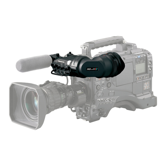
1-inch Electronic HD Color View Finder
1-Zoll Elektronischer HD-Farbe-Sucher
HD Couleur Viseur électronique de 1 pouce
HD Colore Mirino Elettronico da 1 pollici
HD Color Visor Electrónico de 1 pulgadas
1 型 HD カラービューファインダー
Model No.
製造番号は、品質管理上重要なものです。
製品本体と保証書の製造番号をお確かめください。
取扱説明書
AJ-CVF100G
日
本
語
VQT2C51
Werbung
Kapitel
Inhaltsverzeichnis

Verwandte Anleitungen für Panasonic AJ-CVF100G


Inhaltszusammenfassung für Panasonic AJ-CVF100G
- Seite 1 HD Couleur Viseur électronique de 1 pouce HD Colore Mirino Elettronico da 1 pollici HD Color Visor Electrónico de 1 pulgadas 1 型 HD カラービューファインダー AJ-CVF100G Model No. Before operating this product, please read the instructions carefully and save this manual for future use.
-
Seite 2: Read This First
ENGLISH Read this first! For General _ DO NOT REMOVE PANEL COVERS BY UNSCREWING THEM. No user serviceable parts inside. Refer servicing to qualified service personnel. WARNING: TO REDUCE THE RISK OF FIRE OR SHOCK HAZARD, DO NOT EXPOSE THIS EQUIPMENT TO RAIN OR MOISTURE. - Seite 3 Read this first! (Continued) For USA This device complies with part 15 of the FCC Rules. Operation is subject to the following two conditions: (1) This device may not cause harmful interference, and (2) this device must accept any interference received, including interference that may cause undesired operation. FCC Note: This equipment has been tested and found to comply with the limits for a class B digital device, pursuant to Part 15 of the FCC Rules.
-
Seite 4: Inhaltsverzeichnis
Table of Contents Read this first! ....................1 Features ......................4 Parts and Their Functions ................4 Adjusting the Viewfinder .................. 7 Attaching the Viewfinder....................7 Adjusting the Viewfinder’s left-right position..............8 Adjusting the Viewfinder’s front-back position............... 8 Detaching the Viewfinder ....................9 Diopter Adjustment...................... -
Seite 5: Features
Features It is compatible with Multi-format (1080i/720P). High resolution color LCD panel will display fine images, making it easy to focus. With the 1-inch LCOS panel, it has realized fast response and high resolution equivalent to a CRT. This unit is same size as the conventional B&W HD viewfinder, making it possible to replace without any modification. - Seite 6 Parts and Their Functions (Continued) TALLY Switch Controls the front tally lamp. HIGH: Makes the front tally lamp brighter. OFF: Turns the tally lamp off. LOW: Makes the front tally lamp dimmer. PEAKING Control Adjusts the outlines of the images in the viewfinder to make focusing easier. The setting of this control has no effect on the output signal of the camera.
- Seite 7 Parts and Their Functions (Continued) Internal LEDs Indicators and displayed screen content are different depending on the camera used. Refer to the instruction manual of the camera for details. TALLY / REC BATT SAVE Green TALLY Indicator Lights in green when a green TALLY signal is received from the camera control unit. TALLY/REC Indicator Lights in red during the recording, or when the red TALLY signal is received from the camera control unit.
-
Seite 8: Adjusting The Viewfinder
Adjusting the Viewfinder Attaching the Viewfinder Confirm that the POWER switch of the camera is “OFF”. Insert the plug into the connection jack of the viewfinder. <Note> Be sure to insert the plug all the way into the connection jack. Loosen the ring. -
Seite 9: Adjusting The Viewfinder's Left-Right Position
Adjusting the Viewfinder (Continued) Adjusting the Viewfinder’s left-right position Loosen the viewfinder left-right position anchoring ring. Slide the viewfinder to the left or right, and adjust it to a position that allows easy viewing. Viewfinder left-right Tighten the ring. position anchoring ring Tighten the viewfinder left-right position anchoring ring. -
Seite 10: Detaching The Viewfinder
Adjusting the Viewfinder (Continued) Detaching the Viewfinder Confirm that the POWER switch of the camera is “OFF”. Loosen the viewfinder left-right position anchoring ring. While pulling up the viewfinder stopper, remove the viewfinder by sliding it in the direction of the arrow. Loosen the ring. -
Seite 11: Diopter Adjustment
Adjusting the Viewfinder (Continued) Diopter Adjustment Set the POWER switch of the camera to “ON”. A picture will appear in the viewfinder. Turn the diopter adjustment ring to adjust the diopter so that the viewfinder picture can be clearly seen. Diopter adjustment ring Screen Adjustment Adjust the condition of the viewfinder screen. -
Seite 12: Cleaning The Eyepiece
Cleaning the Eyepiece Remove the eyepiece to clean off any dust that got on the LCOS panel screen or mirror. <Note> Do not wipe the mirror surface under any circumstances as it has been specially treated. Dust which has adhered to the mirror should be blown away with a blower, etc. Turn the lock ring as far as Alignment marks Eyepiece... -
Seite 13: Attaching The Microphone
Attaching the Microphone Follow the steps below to install the AJ-MC700P or the AJ-MC900G microphone kit (sold separately). Open the microphone holder. Viewfinder Microphone holder Attach the microphone. Plug the microphone connector cable into the MIC IN jack. MIC IN jack E-12... -
Seite 14: Specifications
Specifications Power supply: DC 12 V (supplied by camera) Power consumption: 5.0 W indicates safety information. Display panel: 1-inch LCOS panel Image system: Compatible with automatic switching to the following images 1080/50i, 1080/59.94i, 1080/60i, 720/59.94P, 720/60P External adjustment controls: Controls (BRIGHT, CONTRAST, CHROMA, PEAKING) Switches (TALLY HIGH/OFF/LOW, ZEBRA ON/OFF, CHROMA ON/OFF) - Seite 15 Information on Disposal for Users of Waste Electrical & Electronic Equipment (private households) This symbol on the products and/or accompanying documents means that used electrical and electronic products should not be mixed with general household waste. For proper treatment, recovery and recycling, please take these products to designated collection points, where they will be accepted on a free of charge basis.
- Seite 16 DEUTCH Bitte lesen! _ Öffnen Sie nicht das Gerät durch Abschrauben von Gehäuseteilen. Im Geräteinneren befinden sich keine Teile, die vom Benutzer gewartet werden können. Wartungs- und Reparaturarbeiten grundsätzlich autorisiertem Kundendienstpersonal überlassen. WARNUNG: ZUR REDUZIERUNG DER GEFAHR VON BRAND UND ELEKTRISCHEM SCHLAG DIESES GERÄT WEDER NÄSSE NOCH FEUCHTIGKEIT AUSSETZEN.
-
Seite 17: Merkmale
Merkmale Es ist mit dem Multi-Format kompatibel (1080i/720P). Ein hoch auflösendes Farb-LCD-Panel zeigt genaue Bilder an, was das Fokussieren einfach macht. Mit dem 1-Zoll LCOS-Panel wurden eine schnelle Ansprache und eine hohe Auflösung erreicht, vergleichbar mit einem CRT. Dieses Gerät hat die gleiche Größe wie ein konventioneller Schwarzweiß-HD-Sucher, was einen Austausch ohne eine Veränderung ermöglicht. -
Seite 18: Vordere Signallampe
Teile und ihre Funktionen (Fortsetzung) Signallampenschalter [TALLY] Steuert die vordere Signallampe. HIGH: Erhöht die Helligkeit der vorderen Signallampe. OFF: Schaltet die Signallampe aus. LOW: Verringert die Helligkeit der vorderen Signallampe. Regler PEAKING Dient zur Einstellung der Bildkonturen im Sucher, um die Scharfeinstellung zu erleichtern. Die Einstellung dieses Reglers hat keinen Einfluß... - Seite 19 Teile und ihre Funktionen (Fortsetzung) Interne LEDs Inhalte der Anzeigen und Bildschirmanzeigen unterscheiden sich davon, welche Kamera benutzt wird. Einzelheiten sind der Bedienungsanleitung der Kamera zu entnehmen. TALLY / REC BATT SAVE Grüne TALLY-Anzeige Leuchtet grün auf, wenn ein grünes TALLY-Signal von der Bedienungseinheit der Kamera empfangen wird.
-
Seite 20: Einstellen Des Suchers
Einstellen des Suchers Anbringen des Suchers Sicherstellen, daß sich der Schalter POWER der Kamera in der AUS-Stellung befindet. Den Stecker in die Anschlußbuchse des Suchers einführen. <Hinweis> Führen Sie den Stecker bis zum Anschlag in die Anschlußbuchse ein. Den Ring lösen. Querpositions-Feststellring des Suchers Lösen Sie den Querpositions-Feststellring des Suchers. -
Seite 21: Einstellen Der Querposition Des Suchers
Einstellen des Suchers (Fortsetzung) Einstellen der Querposition des Suchers Lösen Sie den Querpositions-Feststellring des Suchers. Schieben Sie den Sucher nach links oder rechts, um seine Position so einzustellen, dass der Suchermonitor bequem ablesbar ist. Den Ring anziehen. Querpositions-Feststellring des Suchers Ziehen Sie den Querpositions-Feststellring des Suchers an. -
Seite 22: Abnehmen Des Suchers
Einstellen des Suchers (Fortsetzung) Abnehmen des Suchers Sicherstellen, daß sich der Schalter POWER der Kamera in der AUS-Stellung befindet. Lösen Sie den Querpositions-Feststellring des Suchers. Entfernen Sie den Sucher durch Schieben in Pfeilrichtung, während Sie den Sucheranschlag hochziehen. Den Ring lösen. Sucheranschlag Lösen Sie das Sucherkabel und das Mikrofonkabel aus den Kabelklemmen, und trennen Sie die Kabel ab. -
Seite 23: Dioptrieneinstellung
Einstellen des Suchers (Fortsetzung) Dioptrieneinstellung Den Schalter POWER der Kamera auf die EIN-Stellung stellen. Ein Bild erscheint im Sucher. Das Okular durch Drehen des Dioptrien-Einstellrings so einstellen, daß das Sucherbild scharf ist. Dioptrien-Einstellring Sucherschirmeinstellung Den Zustand des Sucherschirms einstellen. Helligkeit: Den Regler BRIGHT drehen. Kontrast: Den Regler CONTRAST drehen. -
Seite 24: Reinigen Des Sucherokulars
Reinigen des Sucherokulars Entfernen Sie das okular, um Staub zu entfernen, der auf den LCOS-Panel des Bildschirms oder des Spiegels gelangt ist. <Hinweis> Die Spiegeloberfläche darf unter keinen Umständen abgewischt werden, da sie speziell vergütet ist. Am Spiegel haftender Staub sollte mit einem Blasepinsel oder dergleichen entfernt werden. -
Seite 25: Anbringen Des Mikrofons
Anbringen des Mikrofons Führen Sie die folgenden Schritte aus, um den Mikrofonsatz AJ-MC700P oder AJ- MC900G (getrennt erhältlich) zu montieren. Den Mikrofonhalter öffnen. Sucher Mikrofonhalter Das Mikrofon anbringen. Den Stecker des Mikrofonkabels an die Buchse MIC IN anschließen. Buchse MIC IN G-10... -
Seite 26: Technische Daten
Technische Daten Stromversorgung: 12 V Gleichspannung (Versorgung durch Kamera) Leistungsaufnahme: 5,0 W ist die Sicherheitsinformation. Anzeige: 1-Zoll LCOS-Panel Bildsystem: Kompatibel mit automatischer Umschaltung auf folgende Bilder 1080/50i, 1080/59,94i, 1080/60i, 720/59,94P, 720/60P Externe Regler und Schalter: Regler (BRIGHT, CONTRAST, CHROMA, PEAKING) Schalter (TALLY HIGH/OFF/LOW, ZEBRA ON/OFF, CHROMA ON/OFF) Zulässiger Temperaturbereich:... - Seite 27 Benutzerinformationen zur Entsorgung von elektrischen und elektronischen Geräten (private Haushalte) Dieses Symbol auf Produkten und/oder begleitenden Dokumenten bedeutet, dass verbrauchte elektrische und elektronische Produkte nicht mit gewöhnlichem Haushaltsabfall vermischt werden sollen. Bringen Sie zur ordnungsgemäßen Behandlung, Rückgewinnung und Recycling diese Produkte zu den entsprechenden Sammelstellen, wo sie ohne Gebühren entgegengenommen werden.
-
Seite 28: Lire Ces Informations En Premier
FRANÇAIS Lire ces informations en premier ! _ Ne pas dévisser le couvercle. Il ne se trouve à l’intérieur aucune pièce qui puisse être réparée par l’utilisateur. Confier toute réparation à un personnel qualifié. AVERTISSEMENT: POUR RÉDUIRE LES RISQUES D’INCENDIE OU DE CHOC ÉLECTRIQUE, ÉVITEZ D’EXPOSER CET APPAREIL À... - Seite 29 Table des matières Lire ces informations en premier ! ..............1 Caractéristiques ....................2 Les commandes et leurs fonctions ..............3 Réglage du viseur ..................... 5 Montage du viseur ......................5 Réglage de la position gauche-droite du viseur ............6 Réglage de la position avant-arrière du viseur ..............6 Retrait du viseur ......................7 Réglage de la correction dioptrique................8 Réglage de l’écran......................8...
-
Seite 30: Les Commandes Et Leurs Fonctions
Les commandes et leurs fonctions PEAKING CHROMA CONTRAST BRIGHT Commande PEAKING Commutateur de saturation Il permet de régler les contours de (CHROMA) l’image dans le viseur de façon à les Bascule l’affichage des images entre rendre plus nets. Le réglage de cette Couleurs et B&W sur le viseur. - Seite 31 Les commandes et leurs fonctions (suite) Voyant de signalisation avant S’allume pendant la prise de vues TALLY / REC lorsque le commutateur TALLY est réglé sur HIGH ou LOW. ailleurs, clignote à titre d’avertissement, de la même manière que le voyant REC dans le viseur. La luminosité...
-
Seite 32: Réglage Du Viseur
Réglage du viseur Montage du viseur Vérifier que l’interrupteur POWER de la caméra est éteint (“OFF”). Insérer la fiche dans la prise de raccordement du viseur. <Remarque> Bien insérer la fiche à fond dans la prise de raccordement. Desserrer la bague. Bague d’ancrage de la position gauche-droite du viseur Desserrer la bague d’ancrage de la position gauche-droite du viseur. -
Seite 33: Réglage De La Position Gauche-Droite Du Viseur
Réglage du viseur (suite) Réglage de la position gauche-droite du viseur Desserrer la bague d’ancrage de la position gauche-droite du viseur. Glisser le viseur vers la gauche ou vers la droite, et le régler sur la position permettant une vue facile des données sur l’écran. Bague d’ancrage de la position Serrer la bague. -
Seite 34: Retrait Du Viseur
Réglage du viseur (suite) Retrait du viseur Vérifier que l’interrupteur POWER de la caméra est éteint (“OFF”). Desserrer la bague d’ancrage de la position gauche-droite du viseur. Tout en soulevant la butée du viseur, retirer le viseur en le glissant dans le sens de la flèche. -
Seite 35: Réglage De La Correction Dioptrique
Réglage du viseur (suite) Réglage de la correction dioptrique Mettre l’interrupteur POWER de la caméra sur “ON”. Une image apparaît dans le viseur. Tourner la bague de correction dioptrique de façon que l’image du viseur soit nette. Bague de correction dioptrique Réglage de l’écran Régler les conditions de l’écran du viseur. -
Seite 36: Nettoyage De L'oculaire
Nettoyage de l’oculaire Retirez l’oeilleton pour dépoussiérer l’écran d’affichage LCOS ou le miroir. <Remarque> En aucun cas on n’essuiera la surface du miroir, car elle a été spécialement traitée. La poussière qui colle au miroir devra être enlevée avec une poire soufflante, par exemple. Tourner la bague de verrouillage Repères d’alignement OEilleton... -
Seite 37: Montage Du Microphone
Montage du microphone Pour monter le microphone AJ-MC700P ou AJ-MC900G (vendu séparément), procéder de la façon suivante. Ouvrir le support de microphone. Viseur Support de microphone Monter le microphone. Brancher le câble de raccordement du microphone dans la prise MIC IN. Prise MIC IN F-10... -
Seite 38: Fiche Technique
Fiche technique Alimentation: CC 12 V (fournie par la caméra) Consommation: 5,0 W Informations concernant la sécurité. Panneau d’affichage: Ecran LCOS de 1 pouce Système image: Compatible avec le basculement automatique des images suivantes 1080/50i, 1080/59,94i, 1080/60i, 720/59,94P, 720/60P Commandes de réglage externes: Commandes de niveau (BRIGHT, CONTRAST, CHROMA, PEAKING) Commutateurs... - Seite 39 Informations relatives à l’évacuation des déchets, destinées aux utilisateurs d’appareils électriques et électroniques (appareils ménagers domestiques) Lorsque ce symbole figure sur les produits et/ou les documents qui les accompagnent, cela signifie que les appareils électriques et électroniques ne doivent pas être jetés avec les ordures ménagères. Pour que ces produits subissent un traitement, une récupération et un recyclage appropriés, envoyez-les dans les points de collecte désignés, où...
-
Seite 40: Leggere Prima Quanto Segue
ITALIANO Leggere prima quanto segue! _ ATTENZIONE: All’interno non ci sono parti riparabili dall’utente. Per le riparazioni, rivolgersi a personale tecnico qualificato. ATTENZIONE: PER RIDURRE IL RISCHIO D’INCENDIO O DI SCOSSE, NON ESPORRE QUESTO PRODOTTO ALLA PIOGGIA O ALL’UMIDITÀ. PER RIDURRE IL RISCHIO D’INCENDIO O DI SCOSSE ELETTRICHE, TENERE QUESTO PRODOTTO LONTANO DA TUTTI I LIQUIDI. -
Seite 41: Caratteristiche
Caratteristiche È compatibile con Multi-format (1080i/720P). Il pannello colore LCD ad alta risoluzione visualizzerà immagini nitide, facilitando la messa a fuoco. Con il pannello da LCOS da 1 pollice, è stata ottenuta una risposta rapida e alta risoluzione equivalente a un CRT. Quest’unità... - Seite 42 Parti e loro funzioni (continua) Interruttore TALLY Controlla la spia di ripresa. HIGH: Rende più luminosa la spia di ripresa anteriore. OFF: Spegne la spia di ripresa. LOW: Rende più fioca la spia di ripresa anteriore. Controllo PEAKING Regola i contorni delle immagini nel mirino per facilitare la messa a fuoco. La regolazione di questo controllo non ha alcun effetto sul segnale di uscita della videocamera.
- Seite 43 Parti e loro funzioni (continua) LED interni Gli indicatori e il contenuto della schermata visualizzata differiscono a seconda della videocamera utilizzata. Per i dettagli, riferirsi al manuale di istruzioni della videocamera. TALLY / REC BATT SAVE Indicatore TALLY verde Si illumina di verde quando riceve un segnale TALLY verde dall’unità di controllo della videocamera.
-
Seite 44: Regolazione Del Mirino
Regolazione del mirino Montaggio del mirino Accertarsi che l’interruttore POWER della videocamera sia posizionato su “OFF”. Inserire la spina nella presa di connessione del mirino. <Nota> Inserire completamente la spina nella presa di connessione. Allentare l’anello. Anello di ancoraggio posizione destra/sinistra mirino Allentare l’anello di ancoraggio posizione destra/sinistra mirino. -
Seite 45: Regolazione Della Posizione Destra/Sinistra Del Mirino
Regolazione del mirino (continua) Regolazione della posizione destra/sinistra del mirino Allentare l’anello di ancoraggio posizione destra/sinistra mirino. Spingere il mirino a destra o a sinistra, e regolarlo su una posizione che permetta una comoda visione. Anello di ancoraggio posizione Stringere l’anello. destra/sinistra mirino Stringere l’anello di ancoraggio posizione destra/sinistra mirino. -
Seite 46: Modo Di Staccare Il Mirino
Regolazione del mirino (continua) Modo di staccare il mirino Accertarsi che l’interruttore POWER della videocamera sia posizionato su “OFF”. Allentare l’anello di ancoraggio posizione destra/sinistra mirino. Tirando su il fermo mirino, rimuovere il mirino spingendolo nella direzione della freccia. Allentare l’anello. Fermo mirino Rilasciare il cavo del mirino e il cavo del microfono dai morsetti, e staccare i cavi. -
Seite 47: Regolazione Delle Diottrie
Regolazione del mirino (continua) Regolazione delle diottrie Posizionare l’interruttore POWER della videocamera su “ON”. Sul mirino appaiono le immagini. Girare l’anello di regolazione diottrie per regolare le diottrie in modo da vedere chiaramente le immagini sul mirino. Anello di regolazione diottrie Regolazione dello schermo Regolare la condizione dello schermo del mirino. -
Seite 48: Pulizia Del'oculare
Pulizia del’oculare Rimuovere l’oculare per pulire l’eventuale polvere presente sul pannello LCOS o sullo specchio. <Nota> Non si deve assolutamente strofinare la superficie dello specchio, perché è trattata in modo speciale. La polvere sullo specchio deve essere soffiata via con un soffietto, ecc. Girare al massimo l’anello di Segni di allineamento Oculare... -
Seite 49: Montaggio Del Microfono
Montaggio del microfono Per installare il kit del microfono AJ-MC700P o AJ-MC900G (venduto separatamente), seguire il procedimento dei passi sotto. Aprire il supporto del microfono. Mirino Supporto microfono Montare il microfono. Attaccare il cavo connettore microfono alla presa MIC IN. Presa MIC IN I-10... -
Seite 50: Dati Tecnici
Dati tecnici Alimentazione: CC 12 V (fornita dalla videocamera) Assorbimento di corrente: 5,0 W sono le informazioni sulla sicurezza. Pannello: Pannello LCOS da 1 pollice Sistema immagini: Compatibile con passaggio automatico alle seguenti immagini. 1080/50i, 1080/59,94i, 1080/60i, 720/59,94P, 720/60P Controlli di regolazione esterna: Controlli (BRIGHT, CONTRAST, CHROMA, PEAKING) Interruttori... -
Seite 51: Informazioni Per Gli Utenti Sullo Smaltimento Di Apparecchiature Elettriche Ed Elettroniche Obsolete (Per I Nuclei Familiari Privati)
Informazioni per gli utenti sullo smaltimento di apparecchiature elettriche ed elettroniche obsolete (per i nuclei familiari privati) Questo simbolo prodotti sulla documentazione accompagnamento significa che i prodotti elettrici ed elettronici usati non devono essere mescolati con i rifiuti domestici generici. Per un corretto trattamento, recupero e riciclaggio, portare questi prodotti ai punti di raccolta designati, dove verranno accettati gratuitamente. -
Seite 52: Lea Esto Primero
ESPANÕL Lea esto primero _ NO QUITE LA CUBIERTA DESATORNILLÁNDOLA. Las piezas del interior no requieren mantenimiento por parte del usuario. Solicite las reparaciones al personal de servicio calificado. ADVERTENCIA: PARA REDUCIR EL RIESGO DE PRODUCIR UN INCENDIO O RECIBIR UNA DESCARGA ELÉCTRICA, NO EXPONGA ESTE EQUIPO A LA LLUVIA NI A LA HUMEDAD. -
Seite 53: Características
Características Compatible con Multi-formato (1080i/720P). Panel LCD en color con alta resolución que muestra detalladas imágenes, lo que facilita el enfoque. Con el panel LCOS de 1 pulgada, ha demostrado una rápida respuesta y una alta resolución equivalentes a las de un CRT. Esta unidad tiene el mismo tamaño que el visor convencional HD B/N, lo que posibilita su sustitución sin realizar ninguna modificación. - Seite 54 Partes y sus funciones (Continuación) Conmutador TALLY Controla la lámpara indicadora. HIGH: Hace que la lámpara indicadora delantera brille más. OFF: Apaga la lámpara indicadora. LOW: Hace que la lámpara indicadora delantera brille menos. Control PEAKING Ajusta los contornos de las imágenes en el visor para facilitar el enfoque. El ajuste de este control no tiene ningún efecto en las señales de salida de la videocámara.
- Seite 55 Partes y sus funciones (Continuación) LEDs internos Los indicadores y el contenido que se muestra en la pantalla varían dependiendo de la cámara que se utilice. Consulte el manual de instrucciones de la videocámara para tener detalles. TALLY / REC BATT SAVE Indicador verde TALLY...
-
Seite 56: Ajuste Del Visor
Ajuste del visor Montaje del visor Confirme que el conmutador POWER de la videocámara esté en “OFF”. Inserte la clavija en la toma de conexión del visor. <Nota> Asegúrese de insertar a fondo la clavija en la toma de conexión. Afloje el anillo. -
Seite 57: Ajuste De La Posición Hacia La Derecha O Hacia La Izquierda Del Visor
Ajuste del visor (Continuación) Ajuste de la posición hacia la derecha o hacia la izquierda del visor Afloje el anillo de fijación de la posición hacia la derecha o hacia la izquierda del visor. Deslice el visor hacia la derecha o hacia la izquierda y ajústelo en una posición que permita ver su pantalla fácilmente. -
Seite 58: Desmontaje Del Visor
Ajuste del visor (Continuación) Desmontaje del visor Confirme que el conmutador POWER de la videocámara esté en “OFF”. Afloje el anillo de fijación de la posición hacia la derecha o hacia la izquierda del visor. Mientras tira hacia arriba del tope del visor, retire el visor deslizándolo en el sentido de la flecha. -
Seite 59: Ajuste De Dioptrías
Ajuste del visor (Continuación) Ajuste de dioptrías Ponga el conmutador POWER de la videocámara en “ON”. En el visor aparecerá una imagen. Gire el anillo de ajuste de dioptrías de forma que la imagen del visor pueda verse claramente. Anillo de ajuste de dioptrías Ajuste de pantalla Ajuste la condición de la pantalla del visor. -
Seite 60: Limpieza Del Ocular
Limpieza del ocular Retire el ocular para limpiar el polvo que haya podido adherirse sobre la pantalla del panel LCOS o sobre el espejo. <Nota> No frote la superficie del espejo bajo ninguna circunstancia porque ha sido tratada especialmente. El polvo adherido al espejo deberá quitarse con un soplador, etc. Gire todo lo posible hacia la Marcas de alineación Ocular... -
Seite 61: Montaje Del Micrófono
Montaje del micrófono Siga los pasos de abajo para instalar el juego del micrófono AJ-MC700P o AJ-MC900G (vendido por separado). Abra el soporte del micrófono. Visor Soporte del micrófono Monte el micrófono. Enchufe el cable del micrófono en la toma MIC IN. Toma MIC IN S-10... -
Seite 62: Especificaciones
Especificaciones Alimentación: CC 12 V (suministrada por la videocámara) Consumo: 5,0 W indica información de seguridad. Panel: Panel LCOS de 1 pulgada Sistema de imagen: Compatible con la conmutación automática a los siguientes formatos de imágenes 1080/50i, 1080/59,94i, 1080/60i, 720/59,94P, 720/60P Controles de ajuste externo: Controles (BRIGHT, CONTRAST, CHROMA, PEAKING) - Seite 63 Información sobre la eliminación para los usuarios de equipos eléctricos y electrónicos usados (particulares) La aparición de este símbolo en un producto y/o en la documentación adjunta indica que los productos eléctricos y electrónicos usados no deben mezclarse con la basura doméstica general. Para que estos productos se sometan a un proceso adecuado de tratamiento, recuperación y reciclaje, llévelos a los puntos de recogida designados, donde los admitirán sin coste alguno.
- Seite 64 日本語 目 次 安全上のご注意 ....................2 特 長 ......................5 各部の名称と機能 ..................... 5 ビューファインダーの調整 ................8 ビューファインダーの取り付け ................. 8 ビューファインダーの左右位置調整 ................9 ビューファインダーの前後位置調整 ................9 ビューファインダーの取り外し ................10 視度調整 ........................11 画面調整 ........................11 アイピースのお手入れ ..................12 マイクを取り付ける ..................13 保証とアフターサービス ................14 定 格 ......................15...
-
Seite 65: 安全上のご注意
安全上のご注意 必ずお守りください 安全上のご注意 人への危害、財産の損害を防止するため、必ずお守りいただくことを説明しています。 ■ 誤った使い方をしたときに生じる危害や損害の程度を区分して、 説明していま す。 警告 「死亡や重傷を負うおそれがある内容」です。 注意 「傷害を負うことや、財産の損害が発生するおそれがある内容」です。 ■ お守りいただく内容の種類を、次の絵表示で区分し、説明しています。 このような絵表示は、してはいけない「禁止」内容です。 このような絵表示は、必ず実行していただく「強制」内容です。 日 本 語... - Seite 66 警告 _ コードが破損するようなことはしない [傷つける、 加工する、 高温部や熱機器具に近づける、 無理に曲げる、 ね じる、 引っ張る、 重いものを載せる、 束ねるなど] (傷んだまま使用すると、 火災 ・ ショートの原因になります。 ) ⇒ コードの修理は、 お買い上げの販売店にご相談ください。 _ 乗り物を運転しながら使わない (事故の誘発につながります。 ) ⇒ 歩行中でも周囲の状況、 路面の状態などに十分ご注意ください。 _ 分解や改造をしない (火災の原因になります。 また、 使用機器を損傷することがあります。 ) 分解禁止 _ 異常があったときは、 接続プラグを外す [内部に金属や水などの液体、 異物が入ったとき、 落下などで外装ケー スが破損したとき、...
- Seite 67 注意 _ 直射日光の当たる場所や異常に温度が高くなる場所に置かない (特に真夏の車内、 車のトランクの中は、 想像以上に高温 (約60℃以上) になります。 本機を絶対に放置しないでください。 外装ケースや内部部品が劣化するほか、 火災 の原因になります。 ) _ アイピースを太陽や強い光源に向けない (レンズにより集光されると、 内部部品が 加熱 ・ 破損し、 火災、 故障の原因となりま す。 ) _ 本機の放熱を妨げない [押し入れや本箱など狭いところに入れない、 テーブルクロスを掛けた りじゅうたんや布団の上に置かない] (内部に熱がこもり、 火災の原因になります。 ) _ 油煙や湯気の当たるところ、 湿気やほこりの多いところに置かない (電気が油や水分、 ほこりを伝わり、 火災の原因になることがあります。 ) _ お手入れの際は安全のため、 接続プラグを抜く (火災の原因になります。...
-
Seite 68: 特 長
特 長 マルチフォーマット( 1080i/720P )に対応しています。 高解像度カラー液晶パネルがきめ細かな画像を映し出し、 フォーカス操作を容易に行う ことができます。 1 インチ LCOS パネルの採用で、 CRT 並みの高速応答性、高解像度を実現しています。 本機は従来の白黒 HD ビューファインダーと同サイズですので、そのまま置き換えが可 能です。 (本機は AJ-HDX900 、 AJ-HDX400A 、 AJ-HPX シリーズなどに対応しています。 その他のカメラにつきましては、販売店にご相談ください) CHROMA スイッチを使って、簡単にカラー / 白黒モードを切り替えることができます。 各部の名称と機能 PEAKING CHROMA CONTRAST BRIGHT CHROMA スイッチ ビューファインダーに表示する画像をカラー / 白黒で切り替えます。 カラー画像を表示します。 OFF: 白黒画像を表示します。... - Seite 69 各部の名称と機能 (続き) TALLY スイッチ フロントタリーランプをコントロールします。 HIGH: フロントタリーランプが明るくなります。 OFF: フロントタリーランプが消灯します。 LOW: フロントタリーランプが暗くなります。 PEAKING ( ピーキング ) つまみ ピントを合わせやすくするために、 ビューファインダー内の映像の輪郭を調整します。 カメラの出力信号には影響ありません。 CHROMA ( 色 ) つまみ ビューファインダー内の映像の色の濃さを調整します。 カメラの出力信号には影響ありません。 < ノート > 低温下で電源を ON にした直後は、映像の色合いが薄くなる場合があります。 CONTRAST ( 濃淡 ) つまみ ビューファインダー内の画面の濃淡を調整します。 カメラの出力信号には影響ありません。 BRIGHT ( 明るさ ) つまみ ビューファインダー内の画面の明るさを調整します。...
- Seite 70 各部の名称と機能 (続き) 内部 LED 各ランプや画面上の表示内容は、組み合わせるカメラによって異なります。 詳しくは、カメラの取扱説明書をご覧ください。 TALLY / REC BATT SAVE グリーンタリーインジケーター カメラコントロールユニットからグリーンタリー信号を受けると、緑に点灯します。 TALLY/REC インジケーター 記録中、またはカメラコントロールユニットからレッドタリー信号を受けると、赤に 点灯します。また異常が発生したときは赤色に点滅します。 !インジケーター カメラ本体メニューの! LED 項目で、!インジケーターの点灯条件が設定できます。 各種操作の誤操作防止などにご使用ください。 BATT インジケーター バッテリーの状態によって、点滅または点灯します。点滅・点灯する条件は、カメラ の設定によって変わります。 SAVE インジケーター カメラの SAVE スイッチが ON のとき、またはカメラの VTR SAVE/STBY スイッチが SAVE 側のときに点灯します。...
-
Seite 71: ビューファインダーの調整
ビューファインダーの調整 ビューファインダーの取り付け カメラの POWER スイッチが「 OFF 」であることを確認します。 ビューファインダー接続端子にプラグを接続します。 < ノート > ビューファインダー接続端子にプラグを接続するときはしっかり確実に押し込んで ください。 ゆるめる ビューファインダー 左右位置固定リング ビューファインダー左右位置固定リングをゆるめます。 ビューファインダーストッパーを引き上げながら、ビューファインダーを矢印の方 向へスライドさせて取り付けます。取り付け後、ストッパーがかかったことをご確 認ください。 ビューファインダー ストッパー ビューファインダー左右位置固定リングを締めます。 日 本 語... -
Seite 72: ビューファインダーの左右位置調整
ビューファインダーの調整 (続き) ビューファインダーの左右位置調整 ビューファインダー左右位置固定リングをゆるめます。 ビューファインダーを左右にスライドさせ、見やすい位置に調整します。 ビューファインダー 締める 左右位置固定リング ビューファインダー左右位置固定リングを締めます。 ビューファインダーの前後位置調整 ビューファインダー前後位置固定レバーをゆるめます。 ビューファインダーを前後にスライドさせ、見やすい位置に調整します。 ビューファインダー前後位置固定レバー ビューファインダー前後位置固定レバーを締めます。... -
Seite 73: ビューファインダーの取り外し
ビューファインダーの調整 (続き) ビューファインダーの取り外し カメラの POWER スイッチが「 OFF 」であることを確認します。 ビューファインダー左右位置固定リングをゆるめます。 ビューファインダーストッパーを引き上げながら、ビューファインダーを矢印の方 向へスライドして取り外します。 ゆるめる ビューファインダー ストッパー ビューファインダーケーブルとマイクケーブルをクランプから外し、それぞれの ケーブルを抜きます。 日 本 語 J-10... -
Seite 74: 視度調整
ビューファインダーの調整 (続き) 視度調整 カメラの POWER スイッチを「 ON 」にします。ビューファインダーに画像が見え ます。 視度調整リングを回して、ビューファインダーの画像がはっきり見えるように調整 します。 視度調整リング 画面調整 ビューファインダーの画面の状態を調整します。 明るさ : BRIGHT つまみで調整します。 濃 淡 : CONTRAST つまみで調整します。 色の濃さ : CHROMA つまみで調整します。 輪 郭 : PEAKING つまみで調整します。 PEAKING CHROMA CONTRAST BRIGHT PEAKING つまみ CHROMA つまみ CONTRAST つまみ BRIGHT つまみ... -
Seite 75: アイピースのお手入れ
アイピースのお手入れ LCOS パネル画面やミラーにほこりが付着した場合、 アイピースを取り外して除去してく ださい。 < ノート > ミラーは表面に特殊処理をほどこしていますので、絶対にふかないでください。ほこりが 付着した時はブロワなどで、ふき飛ばしてください。 ロックリングを時計と反対方向 合いマーク アイピース にいっぱいに回し、ロックリン グとビューファインダーの筒の ロックリング 合いマークを合わせます。 アイピースを抜き取ります。 再び取りつけるには ロックリングの合いマークを ビューファインダーの筒の合い マークに合わせ、アイピースを 差し込みます。 日 本 語 ロックリングを時計方向に、 の位置まで確実に回して LOCK ください。 J-12... -
Seite 76: マイクを取り付ける
マイクを取り付ける マイクキット AJ-MC700P 、 AJ-MC900G (別売品) のマイクを取りつけることができます。 マイクホルダーを開きます。 ビューファインダー マイクホルダー マイクを取りつけます。 マイクの接続ケーブルをカメラの MIC IN 端子に接続します。 MIC IN 端子 J-13... -
Seite 77: 保証とアフターサービス
修用性能部品を、製造打ち切り後 8 年間 保有しています。 ※ 補修用性能部品とは、その製品の機能 を維持するために必要な部品です。 修理を依頼されるとき この取扱説明書を再度ご確認の上、お買 ご連絡いただきたい内容 い上げの販売店までご連絡ください。 1 型 HD カラー 日 品 名 本 ◆ 保証期間中の修理は. . . ビューファインダー 語 AJ-CVF100G 保証書の記載内容に従って、修理させて 品 番 いただきます。詳しくは保証書をご覧く 製造番号 ださい。 お買い上げ日 故障の状況 ◆ 保証期間経過後の修理は. . . 修理により、機能、性能の回復が可能な 場合は、ご希望により有料で修理させて いただきます。 J-14... -
Seite 78: 定 格
定 格 DC 12 V (カメラより供給) 電 源 : 5.0 W 消費電力 : は安全項目です。 表示パネル : 1 インチ LCOS パネル 映像方式 : 以下の映像に自動切換え対応 1080/50i 、 1080/59.94i 、 1080/60i 、 720/59.94P 、 720/60P 外部調整器 : コントロールつまみ ( BRIGHT 、 CONTRAST 、 CHROMA 、 PEAKING ) スイッチ... - Seite 79 ヨーロッパ連合以外の国の廃棄処分に関する情報 このシンボルマークは EU 域内でのみ有効です。 製品を廃棄する場合には、最寄りの市町村窓口、または販売店で、正しい 廃棄方法をお問い合わせください。 日 本 語 J-16...
- Seite 80 Panasonic Broadcast & Television Systems Company Unit Company of Panasonic Corporation of North America Executive Office: One Panasonic Way 4E-7, Secaucus, NJ 07094 Tel: 201-348-7000 Eastern Zone: One Panasonic Way 4E-7, Secaucus, NJ 07094 Tel: 201-348-7196 Southeast Region: Tel: 201-392-6151 Western Zone: 3330 Cahuenga Blvd W., Los Angeles, CA 90068 Tel: 323-436-3608...