Werbung
Verfügbare Sprachen
Verfügbare Sprachen
Quicklinks
Operating Instructions/Bedienungsanleitung
2-inch Electronic HD View Finder/2-Zoll Elektronischer HD-Sucher
HD Viseur électronique de 2 pouce/HD Mirino Elettronico da 2 pollici
Before operating this product, please read the instructions carefully and save this manual for
future use.
Bitte lesen Sie diese Bedienungsanleitung vor der Inbetriebnahme dieses Produkts
aufmerksam durch, und bewahren Sie sie für späteres Nachschlagen auf.
Avant d'utiliser l'appareil, lire attentivement ce mode d'emploi, et le conserver à des fins de
référence ultérieure.
Prima di far funzionare questo prodotto, leggere attentamente le istruzioni e conservare questo
manuale per riferimenti futuri.
Antes de utilizar este producto, lea cuidadosamente las instrucciones y guarde este manual
por si tiene que utilizarlo en el futuro.
このたびは、 パナソニック製品 をお買い上げいただき、まことにありがとうございます。
O 取扱説明書をよくお読みのうえ、正しく安全にお使いください。
O ご ご 使 使 用 用 前 前 に に 「 「 安 安 全 全 上 上 の の ご ご 注 注 意 意 」 」 ( ( 2 2 〜 〜 5 5 ペ ペ ー ー ジ ジ ) ) を を 必 必 ず ず お お 読 読 み み く く だ だ さ さ い い 。 。
O 保証書は「お買い上げ日・販売店名」などの記入を確かめ、取扱説明書とともに大切に保管し
てください。
F0406T1088 -F @
Printed in Japan
Mode d'emploi/Istruzioni per l'uso
Instrucciones de funcionamiento
HD Visor Electrónico de 2 pulgadas
Model No.
2 型 HD ビューファインダー
AJ-HVF21G
Model No.
AJ-HVF27BG
取扱説明書
VQT0X77-1
日
本
語
Werbung

Verwandte Anleitungen für Panasonic AJ-HVF21G


Inhaltszusammenfassung für Panasonic AJ-HVF21G
- Seite 1 2-inch Electronic HD View Finder/2-Zoll Elektronischer HD-Sucher HD Viseur électronique de 2 pouce/HD Mirino Elettronico da 2 pollici HD Visor Electrónico de 2 pulgadas 2 型 HD ビューファインダー AJ-HVF21G Model No. AJ-HVF27BG Model No. Before operating this product, please read the instructions carefully and save this manual for future use.
- Seite 2 Precautions for Use (General) WARNING: • TO REDUCE THE RISK OF FIRE OR SHOCK HAZARD, DO NOT EXPOSE THIS EQUIPMENT TO RAIN OR MOISTURE. • TO REDUCE THE RISK OF FIRE OR SHOCK HAZARD, KEEP THIS EQUIPMENT AWAY FROM ALL LIQUIDS. USE AND STORE ONLY IN LOCATIONS WHICH ARE NOT EXPOSED TO THE RISK OF DRIPPING OR SPLASHING LIQUIDS, AND DO NOT PLACE ANY LIQUID CONTAINERS ON TOP OF THE EQUIPMENT.
- Seite 3 Precautions for Use (For USA) Notice (U.S.A.only): This product utilizes both a Cathode Ray Tube (CRT) and other components that contain lead. Disposal of these materials may be regulated in your community due to environmental considerations. For disposal or recycling information, please contact your local authorities, or the Electronics Industries Alliance: <http://www.eiae.org.>...
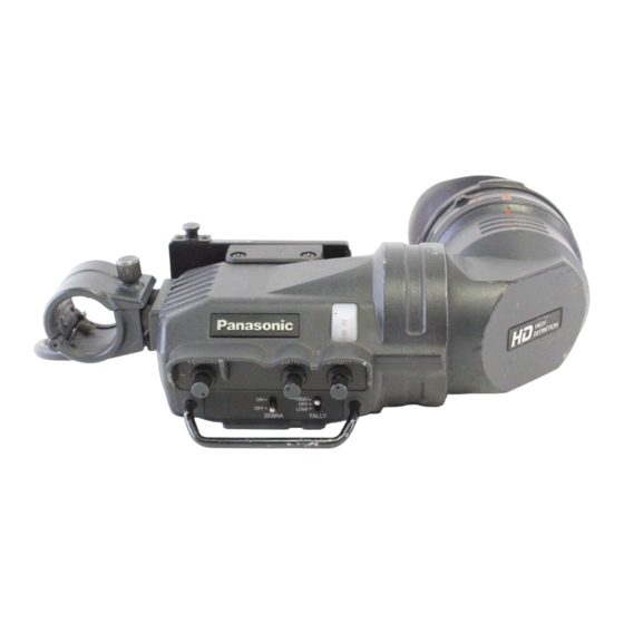
- Seite 4 O The eyepiece is easily detachable. O The image system can be switched between 1080/60 fields and 1080/50 fields depending on the control signal from the camera. (AJ-HVF21G only) Parts and Their Functions 6 >...
- Seite 5 Parts and Their Functions PEAKING Knob Adjusts the outlines of the images in the viewfinder to make focusing easier. The setting of this control has no effect on the output signal of the camera. CONTRAST Knob Adjusts the contrast of the screen inside the viewfinder. The setting of this control has no effect on the output signal of the camera.
- Seite 6 Parts and Their Functions Internal LEDs The lamp and picture tube indications will differ depending on the camera used with the viewfinder. Refer to the instruction manual of the camera for details. TALLY / REC BATT SAVE...
- Seite 7 For cameras compatible with the standard slide rail The following cameras support the standard slide rail. Viewfinder model number Camera model number AJ-HDX400 AJ-HVF21G AJ-HDX400P AJ-HDC27H AJ-HDC27HP AJ-HVF27BG AJ-HDC27HE AJ-HDC27HMC Mounting the Viewfinder Confirm that the POWER switch of the camera is “OFF”.
- Seite 8 For cameras compatible with the standard slide rail Adjusting the viewfinder’s left-right position Loosen the viewfinder left-right position anchoring ring. Slide the viewfinder to the left or right, and adjust it to a position that allows easy viewing. Viewfinder left-right Tighten the ring.
- Seite 9 For cameras compatible with the standard slide rail Detaching the Viewfinder Confirm that the POWER switch of the camera is “OFF”. Loosen the viewfinder left-right position anchoring ring. While pulling up the viewfinder stopper, remove the viewfinder by sliding it in the direction of the arrow.
- Seite 10 To purchase the mounting unit, consult your dealer while bearing in mind that this unit is a repair part. The following cameras support the mounting unit. Viewfinder model number Camera model number AJ-HDC20A AJ-HVF21G AJ-HDC20AP AJ-HDC27F AJ-HDC27FP AJ-HVF27BG AJ-HDC27FE AJ-HDC27FMC...
- Seite 11 For cameras compatible with the mounting unit Mounting the Viewfinder Confirm that the POWER switch of the camera is “OFF”. Insert the plug into the connection jack of the viewfinder. <Note> Be sure to insert the plug all the way into the connection jack. Push the viewfinder down into place.
- Seite 12 For cameras compatible with the mounting unit Position Adjustment Lift up the viewfinder forward-backward/left-right position clamp lever to disengage the lock. Lever Viewfinder Loosen the viewfinder forward-backward/left-right position clamp lever. Adjust the position of the viewfinder by moving it forward, backward, left or right. Return the viewfinder forward-backward/left-right position clamp lever to the locked position.
- Seite 13 Diopter Adjustment Set the POWER switch of the camera to “ON”. A picture will appear in the viewfinder. Turn the diopter adjustment ring to adjust the diopter so that the viewfinder picture can be clearly seen. Diopter Adjustment Ring Screen Adjustment Adjust the condition of the viewfinder screen.
- Seite 14 Detaching the Eyepiece If dust has adhered to the CRT screen or mirror, detach the eyepiece and remove it. <Note> Do not wipe the mirror surface under any circumstances as it has been specially treated. Dust which has adhered to the mirror should be blown away with a blower, etc. Alignment marks Eyepiece Turn the lock ring as far as possible in...
- Seite 15 Mounting the Microphone Follow the steps below to install the AJ-MC700P or the AJ-MC900G microphone kit (sold separately). Open the microphone holder. Viewfinder Microphone holder Mount the microphone. Plug the microphone connector cable into the MIC IN jack. MIC IN jack E-14...
- Seite 16 4.1 W (AJ-HVF27BG) indicates safety information. Picture tube: 2-inch high-resolution monochrome picture tube Image system: 1080 lines, 50/60 fields selectable (AJ-HVF21G) 720 lines, 60 fields (AJ-HVF27BG) External adjustment controls: Controls (BRIGHT, CONTRAST, PEAKING) Switches (TALLY HIGH/OFF/LOW, ZEBRA ON/OFF) Allowable temperature range: 0°C to 40°C (32°F to 104°F)
- Seite 17 Information on Disposal for Users of Waste Electrical & Electronic Equipment (private households) This symbol on the products and/or accompanying documents means that used electrical and electronic products should not be mixed with general household waste. For proper treatment, recovery and recycling, please take these products to designated collection points, where they will be accepted on a free of charge basis.
- Seite 18 Vorsichtsmaßnahmen WARNUNG: • ZUR REDUZIERUNG DER GEFAHR VON BRAND UND ELEKTRISCHEM SCHLAG DIESES GERÄT WEDER NÄSSE NOCH FEUCHTIGKEIT AUSSETZEN. • UM BRAND- ODER STROMSCHLAGGEFAHR ZU REDUZIEREN, MUSS DIESES GERÄT VON ALLEN FLÜSSIGKEITEN FERNGEHALTEN WERDEN. VERMEIDEN SIE GEBRAUCH UND LAGERUNG DES GERÄTES AN ORTEN, AN DENEN DIE GEFAHR BESTEHT, DASS ES MIT FLÜSSIGKEITEN BETROPFT ODER...
- Seite 19 Inhalt Merkmale ............. 3 Teile und ihre Funktionen .
- Seite 20 O Die große Okularöffnung ermöglicht die Betrachtung des Sucherschirms selbst aus größerer Entfernung vom Auge. O Das Okular läßt sich leicht abnehmen. O Das Bildsystem kann, abhängig vom Steuersignal der Kamera, zwischen 1080/60 Halbbilder und 1080/50 Halbbilder umgeschaltet werden. (Nur AJ-HVF21G) Teile und ihre Funktionen 6 > <...
- Seite 21 Teile und ihre Funktionen Konturregler [PEAKING] Dient zur Einstellung der Bildkonturen im Sucher, um die Scharfeinstellung zu erleichtern. Die Einstellung dieses Reglers hat keinen Einfluß auf das Ausgangssignal der Kamera. Kontrastregler [CONTRAST] Dient zur Einstellung des Sucherschirmkontrastes. Die Einstellung dieses Reglers hat keinen Einfluß...
- Seite 22 Teile und ihre Funktionen Interne LEDs Die Lampen und Bildröhrenanzeigen hängen von der mit dem Sucher verwendeten Kamera ab. Einzelheiten sind der Bedienungsanleitung der Kamera zu entnehmen. TALLY / REC BATT SAVE...
- Seite 23 Für Kameras, die mit der Standard-Gleitschiene kompatibel sind Die folgenden Kameras unterstützen die Standard-Gleitschiene. Sucher-Modellnummer Kamera-Modellnummer AJ-HDX400 AJ-HVF21G AJ-HDX400P AJ-HDC27H AJ-HDC27HP AJ-HVF27BG AJ-HDC27HE AJ-HDC27HMC Anbringen des Suchers Sicherstellen, daß sich der Schalter POWER der Kamera in der AUS-Stellung befindet. Den Stecker in die Anschlußbuchse des Suchers einführen.
- Seite 24 Für Kameras, die mit der Standard-Gleitschiene kompatibel sind Einstellen der Querposition des Suchers Lösen Sie den Querpositions-Feststellring des Suchers. Schieben Sie den Sucher nach links oder rechts, um seine Position so einzustellen, dass der Suchermonitor bequem ablesbar ist. Sucher-Querpositions- Den Ring anziehen. Feststellring Ziehen Sie den Querpositions-Feststellring des Suchers an.
- Seite 25 Für Kameras, die mit der Standard-Gleitschiene kompatibel sind Abnehmen des Suchers Confirm that the POWER switch of the camera is “OFF”. Lösen Sie den Querpositions-Feststellring des Suchers. Entfernen Sie den Sucher durch Schieben in Pfeilrichtung, während Sie den Sucheranschlag hochziehen. Den Ring anziehen.
- Seite 26 Die Standard-Gleitschiene kann entfernt und durch die Montageeinheit (VYQ1818) ersetzt werden. Wenn Sie die Montageeinheit kaufen wollen, konsultieren Sie Ihren Händler. Beachten Sie aber, dass diese Einheit ein Ersatzteil ist. Die folgenden Kameras unterstützen die Montageeinheit. Sucher-Modellnummer Kamera-Modellnummer AJ-HDC20A AJ-HVF21G AJ-HDC20AP AJ-HDC27F AJ-HDC27FP AJ-HVF27BG AJ-HDC27FE AJ-HDC27FMC O Umrüsten von Gleitschiene auf Montageeinheit...
- Seite 27 Für Kameras, die mit der Montageeinheit kompatibel sind Anbringen des Suchers Sicherstellen, daß sich der Schalter POWER der Kamera in der AUS-Stellung befindet. Den Stecker in die Anschlußbuchse des Suchers einführen. <Hinweis> Führen Sie den Stecker bis zum Anschlag in die Anschlußbuchse ein. Den Sucher nach unten andrücken.
- Seite 28 Für Kameras, die mit der Montageeinheit kompatibel sind Positionseinstellung Den Sucherpositions-Feststellhebel anheben, um die Verriegelung freizugeben. Hebel Sucher Den Sucherpositions-Feststellhebel lösen. Die Position des Suchers durch Verschieben in die gewünschte Richtung einstellen. Den Sucherpositions-Feststellhebel wieder auf die Verriegelungsstellung zurückstellen. G-11...
- Seite 29 Dioptrieneinstellung Den Schalter POWER der Kamera auf die EIN-Stellung stellen. Ein Bild erscheint im Sucher. Das Okular durch Drehen des Dioptrien-Einstellrings so einstellen, daß das Sucherbild scharf ist. Dioptrien-Einstellring Sucherschirmeinstellung Den Zustand des Sucherschirms einstellen. Helligkeit: Den Regler BRIGHT drehen. Kontrast: Den Regler CONTRAST drehen.
- Seite 30 Abnehmen des Okulars Falls Staub an Sucherschirm oder Spiegel haftet, das Okular lösen und entfernen. <Hinweis> Die Spiegeloberfläche darf unter keinen Umständen abgewischt werden, da sie speziell vergütet ist. Am Spiegel haftender Staub sollte mit einem Blasepinsel oder dergleichen entfernt werden. Ausrichtmarkierungen Okular Den Verriegelungsring so weit wie...
- Seite 31 Anbringen des Mikrofons Führen Sie die folgenden Schritte aus, um den Mikrofonsatz AJ-MC700P oder AJ-MC900G (getrennt erhältlich) zu montieren. Den Mikrofonhalter öffnen. Sucher Mikrofonhalter Das Mikrofon anbringen. Den Stecker des Mikrofonkabels an die Buchse MIC IN anschließen. Buchse MIC IN G-14...
- Seite 32 Leistungsaufnahme: 3,8 W (AJ-HVF21G) 4,1 W (AJ-HVF27BG) ist die Sicherheitsinformation. Bildröhre: Hochauflösende 2-Zoll-Schwarzweiß-Bildröhre Bildsystem: 1080 Zeilen, 50/60 Halbbilder auswählbar (AJ-HVF21G) 720 Zeilen, 60 Halbbilder (AJ-HVF27BG) Externe Regler: Regler (BRIGHT, CONTRAST, PEAKING) Externe Schalter: Schalter (TALLY HIGH/OFF/LOW, ZEBRA ON/OFF) Zulässiger Temperaturbereich: 0°C bis 40°C...
- Seite 33 Benutzerinformationen zur Entsorgung von elektrischen und elektronischen Geräten (private Haushalte) Dieses Symbol auf Produkten und/oder begleitenden Dokumenten bedeutet, dass verbrauchte elektrische und elektronische Produkte nicht mit gewöhnlichem Haushaltsabfall vermischt werden sollen. Bringen Sie zur ordnungsgemäßen Behandlung, Rückgewinnung und Recycling diese Produkte zu den entsprechenden Sammelstellen, wo sie ohne Gebühren entgegengenommen werden.
- Seite 34 Précautions à prendre AVERTISSEMENT: • POUR RÉDUIRE LES RISQUES D’INCENDIE OU DE CHOC ÉLECTRIQUE, ÉVITEZ D’EXPOSER CET APPAREIL À LA PLUIE OU À L’HUMIDITÉ. • POUR RÉDUIRE TOUT RISQUE DE FEU OU DE CHOC ÉLECTRIQUE, ÉLOIGNER L’APPAREIL DES LIQUIDES - UTILISER ET RANGER UNIQUEMENT DANS UN ENDROITNE RISQUANT PAS DE RECEVOIR DES GOUTTES OU D’ÊTRE ASPERGÉ...
- Seite 35 Table des matières Caractéristiques ............3 Les commandes et leurs fonctions .
- Seite 36 O L’œilleton se retire en toute facilité. O Le système image peut être commuté de 1080/60 trames à 1080/50 trames en fonction du signal de commande de la caméra. (AJ-HVF21G uniquement) Les commandes et leurs fonctions 6 > <...
- Seite 37 Les commandes et leurs fonctions Bouton de crête (PEAKING) Il permet de régler les contours de l’image dans le viseur de façon à les rendre plus nets. Le réglage de cette commande est sans effet sur le signal de sortie de la caméra. Bouton de contraste (CONTRAST) Il permet de régler le contraste de l’écran dans le viseur.
- Seite 38 Les commandes et leurs fonctions LED internes Les indications du tube image et des voyants varient en fonction de la caméra utilisée avec le viseur. Pour les détails, voir le mode d’emploi de la caméra. TALLY / REC BATT SAVE...
- Seite 39 Pour les caméras compatibles avec le rail coulissant standard Les caméras suivantes supportent le rail coulissant standard. Numéro de modèle du viseur No. de modèle de la caméra AJ-HDX400 AJ-HVF21G AJ-HDX400P AJ-HDC27H AJ-HDC27HP AJ-HVF27BG AJ-HDC27HE AJ-HDC27HMC Montage du viseur Vérifier que l’interrupteur POWER de la caméra est éteint (“OFF”).
- Seite 40 Pour les caméras compatibles avec le rail coulissant standard Réglage de la position gauche-droite du viseur Desserrer la bague d’ancrage de la position gauche-droite du viseur. Glisser le viseur vers la gauche ou vers la droite, et le régler sur la position permettant une vue facile des données sur l’écran.
- Seite 41 Pour les caméras compatibles avec le rail coulissant standard Retrait du viseur Vérifier que l’interrupteur POWER de la caméra est éteint (“OFF”). Desserrer la bague d’ancrage de la position gauche-droite du viseur. Tout en soulevant la butée du viseur, retirer le viseur en le glissant dans le sens de la flèche.
- Seite 42 (VYQ1818). Pour se procurer le module de montage, consulter son revendeur en sachant que ce module est une pièce de rechange. Les caméras suivantes supportent le module de montage. Numéro de modèle du viseur No. de modèle de la caméra AJ-HDC20A AJ-HVF21G AJ-HDC20AP AJ-HDC27F AJ-HDC27FP AJ-HVF27BG AJ-HDC27FE...
- Seite 43 Pour les caméras compatibles avec le module de montage Montage du viseur Vérifier que l’interrupteur POWER de la caméra est éteint (“OFF”). Insérer la fiche dans la prise de raccordement du viseur. <Remarque> Bien insérer la fiche à fond dans la prise de raccordement. Enfoncer le viseur en place.
- Seite 44 Pour les caméras compatibles avec le module de montage Réglage de la position Soulever le levier de serrage de position avant-arrière/gauche-droite du viseur de façon à dégager le verrouillage. Levier Viseur Desserrer le levier de serrage de position avant-arrière/gauche-droite du viseur. Régler la position du viseur en le déplaçant vers l’avant, l’arrière, la gauche ou la droite.
- Seite 45 Réglage de la correction dioptrique Mettre l’interrupteur POWER de la caméra sur “ON”. Une image apparaît dans le viseur. Tourner la bague de correction dioptrique de façon que l’image du viseur soit nette. Bague de correction dioptrique Réglage de l’écran Régler les conditions de l’écran du viseur.
- Seite 46 Retrait de l’œilleton Si de la poussière colle au tube image ou au miroir, détacher l’œilleton et le retirer. <Remarque> En aucun cas on n’essuiera la surface du miroir, car elle a été spécialement traitée. La poussière qui colle au miroir devra être enlevée avec une poire soufflante, par exemple. Repères d’alignement Œilleton Tourner la bague de verrouillage à...
- Seite 47 Montage du microphone Pour monter le microphone AJ-MC700P ou AJ-MC900G (vendu séparément), procéder de la façon suivante. Ouvrir le support du microphone. Viseur Support de microphone Monter le microphone. Brancher le câble de raccordement du microphone dans la prise MIC IN. Prise MIC IN F-14...
- Seite 48 Informations concernant la sécurité. Tube image: Tube image monochrome haute résolution de 2,0 pouce Système image: 1080 lignes, 50/60 trames sélectionnable parmi (AJ-HVF21G) 720 lignes, 60 trames (AJ-HVF27BG) Commandes de réglage externes: Commandes de niveau (BRIGHT, CONTRAST, PEAKING) Commutateurs (TALLY HIGH/OFF/LOW, ZEBRA ON/OFF) Plage de température admissible:...
- Seite 49 Informations relatives à l’évacuation des déchets, destinées aux utilisateurs d’appareils électriques et électroniques (appareils ménagers domestiques) Lorsque ce symbole figure sur les produits et/ou les documents qui les accompagnent, cela signifie que les appareils électriques et électroniques ne doivent pas être jetés avec les ordures ménagères. Pour que ces produits subissent un traitement, une récupération et un recyclage appropriés, envoyez-les dans les points de collecte désignés, où...
- Seite 50 Precauzioni per l’uso ATTENZIONE: • PER RIDURRE IL RISCHIO D’INCENDIO O DI SCOSSE, NON ESPORRE QUESTO PRODOTTO ALLA PIOGGIA O ALL’UMIDITÀ. • PER RIDURRE IL RISCHIO D’INCENDIO O DI SCOSSE ELETTRICHE, TENERE QUESTO PRODOTTO LONTANO DA TUTTI I LIQUIDI. USARLO E CONSERVARLO SOLTANTO IN LUOGHI CHE NON SIANO ESPOSTI A GOCCIOLAMENTI O SPRUZZI DI LIQUIDI, E NON METTERVI SOPRA RECIPIENTI DI LIQUIDI.
- Seite 51 Sommario Caratteristiche ............3 Parti e loro funzioni .
- Seite 52 O L’oculare può essere staccato facilmente. O A seconda del segnale di controllo della videocamera è possibile impostare il sistema immagini con 1080/60 campi oppure con 1080/50 campi. (solo AJ-HVF21G) Parti e loro funzioni 6 >...
- Seite 53 Parti e loro funzioni Manopola PEAKING Regola i contorni delle immagini nel mirino per facilitare la messa a fuoco. La regolazione di questo controllo non ha alcun effetto sul segnale di uscita della videocamera. Manopola CONTRAST Regola il contrasto dello schermo all’interno del mirino. La regolazione di questo controllo non ha alcun effetto sul segnale di uscita della videocamera.
- Seite 54 Parti e loro funzioni LED interni Le spie e le indicazioni del cinescopio differiscono secondo la videocamera usata con il mirino. Per i dettagli, riferirsi al manuale di istruzioni della videocamera. TALLY / REC BATT SAVE...
- Seite 55 Videocamere compatibili con la rotaia di scorrimento standard La rotaia di scorrimento standard è supportata dalle videocamere seguenti. Numero modello mirino Modello videocamera AJ-HDX400 AJ-HVF21G AJ-HDX400P AJ-HDC27H AJ-HDC27HP AJ-HVF27BG AJ-HDC27HE AJ-HDC27HMC Montaggio del mirino Accertarsi che l’interruttore POWER della videocamera sia posizionato su “OFF”.
- Seite 56 Videocamere compatibili con la rotaia di scorrimento standard Regolazione della posizione destra/sinistra del mirino Allentare l’anello di ancoraggio posizione destra/sinistra mirino. Spingere il mirino a destra o a sinistra, e regolarlo su una posizione che permetta una comoda visione. Anello di ancoraggio posizione Stringere l’anello.
- Seite 57 Videocamere compatibili con la rotaia di scorrimento standard Modo di staccare il mirino Accertarsi che l’interruttore POWER della videocamera sia posizionato su “OFF”. Allentare l’anello di ancoraggio posizione destra/sinistra mirino. Tirando su il fermo mirino, rimuovere il mirino spingendolo nella direzione della freccia.
- Seite 58 (VYQ1818). Per acquistare l’unità di montaggio, rivolgersi al rivenditore tenendo presente che questa unità è una parte di ricambio. L’unità di montaggio è supportata dalle videocamere seguenti. Numero modello mirino Modello videocamera AJ-HDC20A AJ-HVF21G AJ-HDC20AP AJ-HDC27F AJ-HDC27FP AJ-HVF27BG AJ-HDC27FE AJ-HDC27FMC O Cambiamento dalla rotaia di scorrimento all’unità...
- Seite 59 Videocamere compatibili con l’unità di montaggio Montaggio del mirino Accertarsi che l’interruttore POWER della videocamera sia posizionato su “OFF”. Inserire la spina nella presa di connessione del mirino. <Nota> Inserire completamente la spina nella presa di connessione. Spingere giù il mirino in posizione. Stringere saldamente la vite di fermo.
- Seite 60 Videocamere compatibili con l’unità di montaggio Regolazione della posizione Sollevare la leva di fissaggio posizione avanti-indietro/destra-sinistra mirino per rilasciare il bloccaggio. Leva Mirino Allentare la leva di fissaggio posizione avanti-indietro/destra-sinistra mirino. Regolare la posizione del mirino spostandolo in avanti-indietro, a destra o a sinistra.
- Seite 61 Regolazione delle diottrie Posizionare l’interruttore POWER della videocamera su “ON”. Sul mirino appaiono le immagini. Girare l’anello di regolazione diottrie per regolare le diottrie in modo da vedere chiaramente le immagini sul mirino. Anello di regolazione diottrie Regolazione dello schermo Regolare la condizione dello schermo del mirino.
- Seite 62 Modo di staccare l’oculare Se sullo schermo CRT o sullo specchio c’è della polvere, staccare l’oculare per toglierla. <Nota> Non si deve assolutamente strofinare la superficie dello specchio, perché è trattata in modo speciale. La polvere sullo specchio deve essere soffiata via con un soffietto, ecc. Segni di allineamento Oculare Girare...
- Seite 63 Montaggio del microfono Per installare il kit del microfono AJ-MC700P o AJ-MC900G (venduto separatamente), seguire il procedimento dei passi sotto. Aprire il supporto del microfono. Mirino Supporto microfono Montare il microfono. Attaccare il cavo connettore microfono alla presa MIC IN. Presa MIC IN I-14...
- Seite 64 Dati tecnici Alimentazione: C.c. 12 V (fornita dalla videocamera) Assorbimento di corrente: 3,8 W (AJ-HVF21G) 4,1 W (AJ-HVF27BG) sono le informazioni sulla sicurezza. Cinescopio: Cinescopio 2 pollici monocromatico ad alta risoluzione Sistema immagini: 1080 righe, 50/60 campi selezionabili (AJ-HVF21G) 720 righe, 60 campi (AJ-HVF27BG)
- Seite 65 Informazioni per gli utenti sullo smaltimento di apparecchiature elettriche ed elettroniche obsolete (per i nuclei familiari privati) Questo simbolo prodotti sulla documentazione accompagnamento significa che i prodotti elettrici ed elettronici usati non devono essere mescolati con i rifiuti domestici generici. Per un corretto trattamento, recupero e riciclaggio, portare questi prodotti ai punti di raccolta designati, dove verranno accettati gratuitamente.
- Seite 66 Precauciones para la utilización ADVERTENCIA: • PARA REDUCIR EL RIESGO DE PRODUCIR UN INCENDIO O RECIBIR UNA DESCARGA ELÉCTRICA, NO EXPONGA ESTE EQUIPO A LA LLUVIA NI A LA HUMEDAD. • PARA REDUCIR EL RIESGO DE INCENDIO O SACUDIDA ELÉCTRICA, MANTENGA ESTE EQUIPO ALEJADO DE TODOS LOS LÍQUIDOS.
- Seite 67 Índice Características ............3 Partes y sus funciones .
- Seite 68 O El ocular puede desmontarse fácilmente. O El sistema de imágenes se puede cambiar entre 1080/60 campos y 1080/50 campos dependiendo de la señal de control desde la cámara. (sólo AJ-HVF21G) Partes y sus funciones 6 >...
- Seite 69 Partes y sus funciones Control PEAKING Ajusta los contornos de las imágenes en el visor para facilitar el enfoque. El ajuste de este control no tiene ningún efecto en las señales de salida de la videocámara. Control CONTRAST Ajusta el contraste de la pantalla en el interior del visor. El ajuste de este control no tiene ningún efecto en las señales de salida de la videocámara.
- Seite 70 Partes y sus funciones LEDs internos La lámparas y las indicaciones del tubo de imagen cambiarán según la videocámara utilizada con el visor. Consulte el manual de instrucciones de la videocámara para tener detalles. TALLY / REC BATT SAVE...
- Seite 71 Para cámaras compatibles con el riel de deslizamiento estándar Las cámaras siguientes son compatibles con el riel de deslizamiento estándar. Número de modelo del visor Número de modelo de videocámara AJ-HDX400 AJ-HVF21G AJ-HDX400P AJ-HDC27H AJ-HDC27HP AJ-HVF27BG AJ-HDC27HE AJ-HDC27HMC Montaje del visor Confirme que el conmutador POWER de la videocámara esté...
- Seite 72 Para cámaras compatibles con el riel de deslizamiento estándar Ajuste de la posición hacia la derecha o hacia la izquierda del visor Afloje el anillo de fijación de la posición hacia la derecha o hacia la izquierda del visor. Deslice el visor hacia la derecha o hacia la izquierda y ajústelo en una posición que permita ver su pantalla fácilmente.
- Seite 73 Para cámaras compatibles con el riel de deslizamiento estándar Desmontaje del visor Confirme que el conmutador POWER de la videocámara esté en “OFF”. Afloje el anillo de fijación de la posición hacia la derecha o hacia la izquierda del visor. Mientras tira hacia arriba del tope del visor, retire el visor deslizándolo en el sentido de la flecha.
- Seite 74 (VYQ1818). Para adquirir la unidad de montaje, consulte a su concesionario teniendo en cuenta que esta unidad es una pieza de recambio. Las cámaras siguientes son compatibles con la unidad de montaje. Número de modelo del visor Número de modelo de videocámara AJ-HDC20A AJ-HVF21G AJ-HDC20AP AJ-HDC27F AJ-HDC27FP AJ-HVF27BG AJ-HDC27FE AJ-HDC27FMC O Cambio del riel de deslizamiento a la unidad de montaje.
- Seite 75 Para cámaras compatibles con la unidad de montaje Montaje del visor Confirme que el conmutador POWER de la videocámara esté en “OFF”. Inserte la clavija en la toma de conexión del visor. <Nota> Asegúrese de insertar a fondo la clavija en la toma de conexión. Empuje el visor hacia abajo para colocarlo en su lugar.
- Seite 76 Para cámaras compatibles con la unidad de montaje Ajuste de posición Levante la palanca de fijación de posición hacia adelante-atrás/izquierda-derecha del visor para soltar el cierre. Palanca Visor Afloje la palanca de fijación de posición hacia adelante-atrás/izquierda-derecha del visor. Ajuste la posición del visor moviéndolo hacia adelante, atrás, izquierda o derecha. Vuelva a poner la palanca de fijación de posición hacia adelante-atrás/izquierda- derecha del visor en la posición de bloqueo.
- Seite 77 Ajuste de dioptrías Ponga el conmutador POWER de la videocámara en “ON”. En el visor aparecerá una imagen. Gire el anillo de ajuste de dioptrías de forma que la imagen del visor pueda verse claramente. Anillo de ajuste de dioptrías Ajuste de pantalla Ajuste la condición de la pantalla del visor.
- Seite 78 Desmontaje del ocular Si se ha adherido polvo a la pantalla o espejo del tubo de rayos catódicos, separe el ocular y quite el polvo. <Nota> No frote la superficie del espejo bajo ninguna circunstancia porque ha sido tratada especialmente. El polvo adherido al espejo deberá quitarse con un soplador, etc. Marcas de alineación Ocular Gire todo lo posible hacia la derecha y...
- Seite 79 Montaje del micrófono Siga los pasos de abajo para instalar el juego del micrófono AJ-MC700P o AJ-MC900G (vendido por separado). Abra el soporte del micrófono. Visor Soporte del micrófono Monte el micrófono. Enchufe el cable del micrófono en la toma MIC IN. Toma MIC IN S-14...
- Seite 80 Tubo de imagen: Tubo de imagen monocromo de alta definición de 2 pulgadas Sistema de imagen: 1080 líneas, se puede seleccionar entre 50 campos y 60 campos (AJ-HVF21G) 720 líneas, 60 campos (AJ-HVF27BG) Controles de ajuste externo: Controles (BRIGHT, CONTRAST, PEAKING)
- Seite 81 Información sobre la eliminación para los usuarios de equipos eléctricos y electrónicos usados (particulares) La aparición de este símbolo en un producto y/o en la documentación adjunta indica que los productos eléctricos y electrónicos usados no deben mezclarse con la basura doméstica general.
- Seite 82 保証書別添付 製造番号は、品質管理上重要なものです。 製品本体と保証書の製造番号をお確かめください。 目 次 ........... . . 2 安全上のご注意...
- Seite 83 安全上のご注意 必ずお守りください 人への危害、財産の損害を防止するため、必ずお守りいただくことを説明しています。 ■誤った使い方をしたときに生じる危害や損害の程度を区分して、説明しています。 警告 「死亡や重傷を負うおそれがある内容」です。 注意 「傷害を負うことや、財産の損害が発生するおそれがある内容」です。 ■お守りいただく内容を次の図記号で説明しています。 (次は図記号の例です) 気をつけていただく内容です。 してはいけない内容です。 実行しなければならない内容です。 警告 本機を分解・改造しない 煙が出ている、変なにおいや音 がするなどの異常状態の場合 日 内 部 に 高 電 圧 部 が あ は、接続プラグを抜く 本 り 感 電 ・ 火 災 の 原 因 語 となります。 火災・感電の原因と...
- Seite 84 安全上のご注意 必ずお守りください 警告 確実に固定する 本機を落としたり、破損した場 合は、接続プラグを抜く 外れると、落下したり してけがの原因となり そのまま使用すると、 ます。 火災・感電を起こすお それがあります。 本機の内部に異物や水などが 機器が濡れたり、水が入ら 入った場合は、接続プラグを ないようにする 抜く 火 災 ・ 感 電 の お そ れ があります。 そ の ま ま 使 用 す る 雨 天 ・ 降 雪 ・ 海 岸 ・ と、火災・感電を起...
- Seite 85 安全上のご注意 必ずお守りください 警告 水場で使用しない 不安定な場所に置かない 火災・感電の原因と 落ちたり、倒れたり なります。 してけがの原因とな ります。 水場使用禁止 日 本 語...
- Seite 86 安全上のご注意 必ずお守りください 注意 油煙や湯気、湿気やほこりの アイピースを太陽や強い光源 多い場所に置かない に向けない 火 災 ・ 感 電 の 原 因 と レ ン ズ に よ り 集 光 さ なることがあります。 れ る と 、 内 部 部 品 が 加熱・損傷し、火災、 感 電 、 故 障 の 原 因 と なります。...
- Seite 87 特 長 O 高解像度 CRT が、きめ細かな画像を映し出し、フォーカス操作を容易に行うことがで きます。 O 低フレアの CRT を採用していますので、画面が見やすくなっています。 O 大口径ですので、目を離しても画面は見やすくなっています。 O アイピース部を容易に脱着できます。 O カメラからの制御信号により、映像方式を 1080/60 フィールドと 1080/50 フィー ルドに切り替えることができます。 (AJ-HVF21G のみ) 各部の名称と機能 6 > < ZEBRA (ゼブラパターン) スイッチ ビューファインダー内にゼブラパターンを表示させます。 ON : ゼブラパターンを表示させます。 OFF : ゼブラパターンは表示されません。 ゼブラパターンの種類など表示内容は、組み合わせるカメラによって異なりま 日 す。詳しくは、カメラの取扱説明書をご覧ください。...
- Seite 88 各部の名称と機能 PEAKING (ピーキング) つまみ ピントを合わせやすくするために、ビューファインダー内の映像の輪郭を調整します。 カメラの出力信号には影響ありません。 CONTRAST (濃淡) つまみ ビューファインダー内の画面の濃淡を調整します。 カメラの出力信号には影響ありません。 BRIGHT (明るさ) つまみ ビューファインダー内の画面の明るさを調整します。 カメラの出力信号には影響ありません。 フロントタリーランプ TALLY スイッチが「HIGH」または「LOW」の位置のときに動作し、撮影中に点灯し ます。また、ビューファインダー内の REC ランプと同様に点滅し、警告表示も行いま す。 点灯時の明るさは、TALLY スイッチ (HIGH または LOW) で切り替えることができま す。 ビューファインダーストッパー ビューファインダーの取り付け、取り外しに使用します。 アイピース バックタリーランプ 撮影中に点灯します。また、ビューファインダー内の REC ランプと同様に点滅し、警 告表示も行います。 レバーを OFF 側にすると、バックタリーランプが隠れます。 視度調整リング...
- Seite 89 各部の名称と機能 内部 LED 各ランプやブラウン管の表示内容は、組み合わせるカメラによって異なります。 詳しくは、カメラの取扱説明書をご覧ください。 TALLY / REC BATT SAVE 日 本 語...
- Seite 90 標準スライドレール対応カメラの場合 標準スライドレールには、下記のカメラが対応しています。 ビューファインダーのモデル No. カメラのモデル No. AJ-HDX400 AJ-HVF21G AJ-HDX400P AJ-HDC27H AJ-HDC27HP AJ-HVF27BG AJ-HDC27HE AJ-HDC27HMC ビューファインダーの取り付け カメラの POWER スイッチが「OFF」であることを確認します。 ビューファインダー接続端子にプラグを接続します。 < ノート > ビューファインダー接続端子にプラグを接続するときはしっかり確実に押し込ん でください。 ゆるめる ビューファインダー左右位置固定リングをゆるめます。 ビューファインダーストッパーを引き上げながら、ビューファインダーを矢印の 方向へスライドさせて取り付けます。 ビューファインダー ストッパー ビューファインダー左右位置固定リングを締めます。...
- Seite 91 標準スライドレール対応カメラの場合 ビューファインダーの左右位置調整 ビューファインダー左右位置固定リングをゆるめます。 ビューファインダーを左右にスライドさせ、見やすい位置に調整します。 ビューファインダー 締める 左右位置固定リング ビューファインダー左右位置固定リングを締めます。 ビューファインダーの前後位置調整 ビューファインダー前後位置固定レバーをゆるめます。 ビューファインダーを前後にスライドさせ、見やすい位置に調整します。 ビューファインダー前後位置固定レバー 日 本 語 ビューファインダー前後位置固定レバーを締めます。 J-10...
- Seite 92 標準スライドレール対応カメラの場合 ビューファインダーの取り外し カメラの POWER スイッチが「OFF」であることを確認します。 ビューファインダー左右位置固定リングをゆるめます。 ビューファインダーストッパーを引き上げながら、ビューファインダーを矢印の 方向へスライドして取り外します。 ゆるめる ビューファインダー ストッパー ビューファインダーケーブルとマイクケーブルをクランプから外し、それぞれの ケーブルを抜きます。 J-11...
- Seite 93 取り付けユニット対応カメラの場合 標準のスライドレールを取り外し、取り付けユニット(VYQ1818)に交換することが できます。取り付けユニットをお求めになる場合は、補修部品としてお買い上げの販売店 にお申し付けください。 取り付けユニットには、下記のカメラが対応しています。 ビューファインダーのモデル No. カメラのモデル No. AJ-HDC20A AJ-HVF21G AJ-HDC20AP AJ-HDC27F AJ-HDC27FP AJ-HVF27BG AJ-HDC27FE AJ-HDC27FMC O スライドレールから取り付けユニットへの変更 スライドレール ねじ 2 本を外し、標準のスライドレールを外し ます。 ねじ 取り付けユニット 取り付けユニットを、ねじ 2 本で取り付けます。 ねじ 日 本 語 J-12...
- Seite 94 取り付けユニット対応カメラの場合 ビューファインダーの取り付け カメラの POWER スイッチが「OFF」であることを確認します。 ビューファインダー接続端子にプラグを接続します。 < ノート > ビューファインダー接続端子にプラグを接続するときはしっかり確実に押し込ん でください。 ビューファインダーを押し下げます。 ストッパーネジを確実に締めます。 ストッパーねじ ビューファインダーの取り外し カメラの POWER スイッチが「OFF」であることを確認します。 ストッパーネジを緩め、ビューファインダーを真上に引き上げて、抜き取ります。 < ノート > ビューファインダーを抜き取る時は、両手で行ってください。片手ではスムーズ に取り外すことができない場合があり、またファインダーが破損するおそれがあ ります。 ビューファインダーケーブル端子からプラグを抜き取ります。 ストッパーねじ J-13...
- Seite 95 取り付けユニット対応カメラの場合 位置調整 ビューファインダー前後左右位置固定レバーを引き上げるとロックがはずれます。 レバー ビューファインダー 前後左右位置固定レバーをゆるめます。 ビューファインダーを前後左右に移動させ、位置を調整します。 ビューファインダー前後左右位置固定レバーをロック位置まで締めます。 日 本 語 J-14...
- Seite 96 視度調整 カメラの POWER スイッチを「ON」にします。ビューファインダーに画像が見 えます。 視度調整リングを回して、ビューファインダーの画像がはっきり見えるように調 整します。 視度調整リング 画面調整 ビューファインダーの画面の状態を調整します。 明るさ:BRIGHT つまみで調整します。 濃 淡:CONTRAST つまみで調整します。 輪 郭:PEAKING つまみで調整します。 PEAKING CONTRAST BRIGHT PEAKING つまみ CONTRAST つまみ BRIGHT つまみ カメラの POWER スイッチを「ON」にします。 カメラの OUTPUT スイッチを「BAR」にします。 ビューファインダーの BRIGHT と CONTRAST つまみを回して、画像の明るさ とコントラストを調整します。 PEAKING つまみを回すと、画像をよりシャープに調整できます。 シャープにすると、レンズでのピント合わせがやり易くなります。 J-15...
- Seite 97 アイピースの取り外し CRT 画面やミラーにほこりが付着した場合、アイピースを取り外して除去してください。 < ノート > ミラーは表面に特殊処理をほどこしていますので、絶対にふかないでください。ほこりが 付着した時はブロワなどで、ふき飛ばしてください。 合いマーク アイピース ロックリングを時計と反対方向にいっ ぱいに回し、ロックリングとビューフ ァインダーの筒の合いマークを合わせ ロックリング ます。 アイピースを抜き取ります。 再び取りつけるには 1 ロックリングの合いマークをビューファインダーの筒の合いマークに合わせ、アイ ピースを差し込みます。 2 ロックリングを時計方向に、 の位置まで確実に回してください。 LOCK 日 本 語 J-16...
- Seite 98 マイクを取り付ける マイクキット AJ-MC700P、AJ-MC900G(別売品)のマイクを取りつけることができ ます。 マイクホルダーを開きます。 ビューファインダー マイクホルダー マイクを取りつけます。 マイクの接続ケーブルをカメラの MIC IN 端子に接続します。 MIC IN 端子 J-17...
- Seite 99 お買い上げ日から本体 1 年間 ■補修用性能部品 当社では、ビューファインダーの補修用性能 部品を、製造打ち切り後、8 年間保有してい ます。 ※ 補修用性能部品とは、その製品の機能を維 持するために必要な部品です。 修理を依頼されるとき この取扱説明書を再度ご確認の上、お買い上げ ご連絡いただきたい内容 の販売店までご連絡ください。 品 名 2 型 HD ビューファインダー ◆保証期間中の修理は. . . 品 番 AJ-HVF21G 保証書の記載内容に従って、修理させていた AJ-HVF27BG だきます。詳しくは、保証書をご覧ください。 製造番号 日 本 ◆保証期間経過後の修理は. . . お買い上げ日 語 修理により、機能、性能の回復が可能な場合 は、ご希望により有料で修理させていただき 故障の状況 ます。 J-18...
- Seite 100 消費電力 : 3.8 W (AJ-HVF21G) 4.1 W (AJ-HVF27BG) は安全項目です。 ブラウン管: 2 インチ 高解像度モノクローム管 映像方式 : 1080 本、50/60 フィールド切り替え式 (AJ-HVF21G) 720 本、60 フィールド (AJ-HVF27BG) 外部調整器: コントロールつまみ (BRIGHT, CONTRAST, PEAKING) スイッチ (TALLY HIGH/OFF/LOW, ZEBRA ON/OFF) 許容温度 : 0 ° C 〜 40 ° C 許容湿度...
- Seite 101 ヨーロッパ連合以外の国の廃棄処分に関する情報 このシンボルマークは EU 域内でのみ有効です。 製品を廃棄する場合には、最寄りの市町村窓口、または販売店で、正しい 廃棄方法をお問い合わせください。 日 本 語 J-20...
- Seite 102 MEMO J-21...
- Seite 103 MEMO J-22...