Werbung
Quicklinks
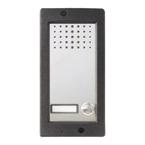
HPC/1÷4 VR
HPV/0÷2 VR
07.2001/2405-5000
BPT S.p.A.
30020 Cinto Caomaggiore
Venezia/Italy
ISTRUZIONI PER
I
L'INSTALLAZIONE
POSTO ESTERNO HPC/1÷4 VR
Togliere la piastrina fermacavi (fig. 6).
Inserire il gruppo audio in alto, vicino
alla testata del telaio (fig. 1-2).
Nel caso di impianti dove può insor-
gere l'effetto Larsen, il microfono può
essere montato in posizione remota,
come indicato nelle figure 3 e 4.
Per scrivere i dati desiderati sul car-
tellino portanome, estrarre il ferma
cartellino e quindi il cartellino (fig. 5).
NOTA. Si possono utilizzare cartellini
portanome personalizzati fino ad un
massimo di 2 mm di spessore.
Effettuare i collegamenti e rimettere la
piastrina fermacavi (fig. 6).
Fissare il telaio alla placca tramite le
due viti in dotazione (fig. 6).
Per montare la placca sulla scatola
incasso avvitare le due viti di fissag-
gio tramite la chiave in dotazione (fig.
7).
Caratteristiche tecniche
• Potenza massima commutabile del
microcontatto: 24V 1A.
• Assorbimento del gruppo di illumi-
nazione: 30mA, 17,5V.
• Temperatura di funzionamento: da
-15 °C a +50 °C.
POSTO ESTERNO HPV/0÷2 VR
Togliere la piastrina fermacavi (fig.
12).
Inserire il gruppo audio-video in alto,
vicino alla testata del telaio (fig. 8-9).
Nel caso di impianti dove può insor-
gere l'effetto Larsen, il microfono può
essere montato in posizione remota,
come indicato nelle figure 10 e 11.
Per scrivere i dati desiderati sul car-
tellino portanome, estrarre il ferma
cartellino e quindi il cartellino (fig. 5).
NOTA. Si possono utilizzare cartellini
portanome personalizzati fino ad un
massimo di 2 mm di spessore.
Effettuare i collegamenti e rimettere la
piastrina fermacavi (fig. 12).
Fissare il telaio alla placca tramite le
due viti in dotazione (fig. 12).
Per montare la placca sulla scatola
incasso avvitare le due viti di fissag-
gio tramite la chiave in dotazione (fig.
1
13).
Caratteristiche tecniche
• Potenza massima commutabile del
microcontatto: 24V 1A.
• Assorbimento del gruppo di illumi-
nazione: 30mA, 17,5V.
• Temperatura di funzionamento: da
-15 °C a +50 °C.
2
GB INSTALLATION
INSTRUCTIONS
HPC/1÷4 VR ENTRY PANEL
Remove the cable-clamp plate (fig.
6).
Insert the audio module at the top,
near to the top moulding of the chas-
sis (fig. 1-2).
In those installations liable to be
affected by the Larsen effect, the
microphone can be fitted in a remote
position, as indicated in figures 3 and
4.
The name card can be removed and
filled in with the relevant information
by removing the card clip followed by
the actual card itself (fig. 5).
NOTE: Personalized name cards can
be used up to a maximum of 2 mm
thick.
Perform the wiring and refit the cable-
clamp plate (fig. 6).
Secure the chassis to the front plate
using the two screws supplied (fig. 6).
In order to fit the front plate on the
embedding box, screw on the two
fastening screws using the screw-
driver supplied (fig. 7).
Technical features
• Max. switching capacity of the
micro-contact: 24V 1A.
• Current demand of the lighting
module: 30mA, 17.5V.
• Working temperature range: from -15
°C to +50 °C.
HPV/0÷2 VR ENTRY PANEL
Remove the cable-clamp plate (fig.
12).
Insert the audio-video module at the
top, near to the top moulding of the
chassis (fig. 8-9).
In those installations liable to be
affected by the Larsen effect, the
microphone can be fitted in a remote
position, as indicated in figures 10
and 11.
The name card can be removed and
filled in with the relevant information
by removing the card clip followed by
the actual card itself (fig. 5).
NOTE: Personalized name cards can
be used up to a maximum of 2 mm
thick.
Perform the wiring and refit the cable-
clamp plate (fig. 12).
Secure the chassis to the front plate
using the two screws supplied (fig. 12).
In order to fit the front plate on the
embedding box, screw on the two
fastening screws using the screw-
driver supplied (fig. 13).
Technical features
• Max. switching capacity of the
micro-contact: 24V 1A.
• Current demand of the lighting
module: 30mA, 17.5V.
• Working temperature range: from -15
°C to +50 °C.
1
Werbung

Verwandte Anleitungen für Bpt HPC/1-4 VR


Inhaltszusammenfassung für Bpt HPC/1-4 VR
- Seite 1 HPC/1÷4 VR ISTRUZIONI PER GB INSTALLATION L’INSTALLAZIONE INSTRUCTIONS HPV/0÷2 VR BPT S.p.A. POSTO ESTERNO HPC/1÷4 VR HPC/1÷4 VR ENTRY PANEL 30020 Cinto Caomaggiore Togliere la piastrina fermacavi (fig. 6). Remove the cable-clamp plate (fig. Venezia/Italy Inserire il gruppo audio in alto, vicino alla testata del telaio (fig.
- Seite 2 INSTALLATIONS- INSTRUCTIONS ANLEITUNG POUR L’INSTALLATION POSTE EXTERIEUR HPC/1÷4 VR AUSSENSTATION HPC/1÷4 VR Enlever la plaquette serre-câbles (fig. Kabelhalterplättchen abnehmen (Abb. 6). Introduire le groupe audio en haut, à Audio oben, an der Stirnseite der côté de l’embout du châssis (fig. 1- Chassis einsetzen (Abb.
- Seite 3 INSTRUCCIONES INSTRUÇÕES PARA LA INSTALACION PARA A INSTALAÇÃO PLACA BOTONEIRA HPC/1÷4 VR PLACA EXTERIOR HPC/1÷4 VR Quitar la plaqueta sujeta-cables (fig. Tirar a placa detentora dos cabos (fig. 6). Inserir o grupo áudio em cima, próxi- Introducir el grupo audio en la parte mo à...