Bpt HPV/1 Installationsanleitung
Aussenstation für videosprechanlagen
- up-ausführung
Quicklinks
1
2
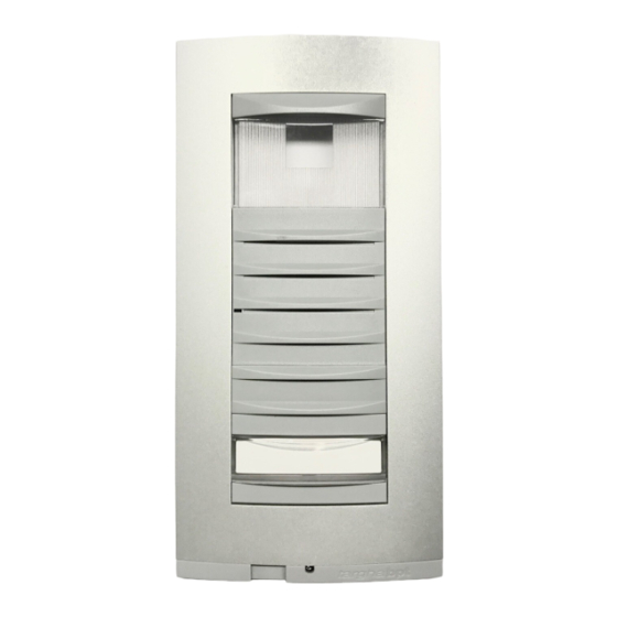
1)Placca/Plate/Tableau/Platine/Placa/
Placa.
2)Microcontatto/Micro-contact/Mikro-
kontakt/Micro-contact/Microcon-
tacto/Micro contacto.
3)Gruppo di illuminazione/Lighting
module/Beleuchtungseinheit/Grou
pe d'éclairage/Grupo de ilumina-
ción/Grupo de iluminação.
11.2000/2403-9411
3
4
4)Piastrina fermacavi/Cable-clamp
plate/Kabelhalterplättchen/Plaque
tte serre-câbles/Plaquita sujetado-
ra/Braçadeira fixa cabos.
HPV/1
BPT S.p.A.
30020 Cinto Caomaggiore
Venezia/Italy
ISTRUZIONI PER
I
L'INSTALLAZIONE
POSTO ESTERNO VIDEOCITOFO-
NICO VERSIONE DA INCASSO
Inserire il gruppo audio-video in alto,
vicino alla testata del telaio (fig. 1).
Nel caso di impianti dove può insor-
gere l'effetto Larsen, il microfono può
essere montato in posizione remota,
come indicato nelle figure 2 e 3.
Applicare il microcontatto (in basso a
destra) nell'apposita sede (fig. 4).
Inserire il gruppo d'illuminazione nel-
l'apposita sede (fig. 5).
Togliere i due bollini di protezione dei
fori filettati nella scatola incasso e fis-
sare il telaio tramite le due viti in dota-
zione (fig. 6). Effettuare i collegamen-
ti e bloccare i cavi utilizzando la pia-
strina fermacavi (fig. 6).
Sulla placca è possibile installare un
ulteriore pulsante; per il suo montag-
gio seguire le istruzioni in dotazione
allo stesso pulsante.
Per scrivere i dati desiderati sul car-
tellino portanome, estrarre il ferma
1
cartellino e quindi il cartellino (fig. 7).
NOTA. Si possono utilizzare cartellini
portanome personalizzati fino ad un
massimo di 2 mm di spessore.
Per montare la placca inserire prima
la parte superiore nella testata e
quindi, tramite una chiave maschio
esagonale s 2,5, avvitare la vite di
bloccaggio (fig. 8).
POSTO ESTERNO VIDEOCITOFO-
NICO VERSIONE DA PARETE
Inserire il gruppo audio-video in alto,
vicino alla testata della base (fig. 9).
Nel caso di impianti dove può insor-
gere l'effetto Larsen, il microfono può
essere montato in posizione remota,
come indicato nelle figure 10 e 11.
Applicare il microcontatto (in basso a
destra) nell'apposita sede (fig. 12).
Inserire il gruppo d'illuminazione nel-
l'apposita sede (fig. 13). Effettuare i
collegamenti e bloccare i cavi utiliz-
zando la piastrina fermacavi (fig. 13).
Sulla placca è possibile installare un
ulteriore pulsante; per il suo montag-
gio seguire le istruzioni in dotazione
allo stesso pulsante.
Per scrivere i dati desiderati sul car-
2
tellino portanome, estrarre il ferma
cartellino e quindi il cartellino (fig. 7).
NOTA. Si possono utilizzare cartellini
portanome personalizzati fino ad un
massimo di 2 mm di spessore.
Per montare la placca inserire prima
la parte superiore nella testata e
quindi, tramite una chiave maschio
esagonale s 2,5, avvitare la vite di
bloccaggio (fig. 14).
Caratteristiche tecniche
• Potenza massima commutabile del
microcontatto: 24V 1A.
• Assorbimento del gruppo di illumi-
nazione: 40mA, 17,5V.
• Temperatura di funzionamento: da
-15 °C a +50 °C.
GB INSTALLATION
INSTRUCTIONS
RECESSED VIDEO ENTRY PANEL
Insert the audio-video module at the
top, near to the top moulding of the
chassis (fig. 1). In those installations
liable to be affected by the Larsen
effect, the microphone can be fitted
in a remote position, as indicated in
figures 2 and 3.
Apply the micro-contact (bottom
right) in the relevant seat (fig. 4).
Insert the lighting module in the rele-
vant seat (fig. 5).
Remove the two plugs protecting the
threaded holes in the embedding box
and secure the chassis using the two
screws supplied (fig. 6).
Perform the wiring and secure the
wires in place using the cable-clamp
plate (fig. 6).
An additional pushbutton can be
installed on the front plate: follow the
instructions supplied with the actual
button for its assembly.
The name card can be removed and
filled in with the relevant information
by removing the card clip followed by
the actual card itself (fig. 7).
NOTE: Personalized name cards can
be used up to a maximum of 2 mm
thick.
In order to fit the front plate, first
insert the upper part in the top moul-
ding and then, using a Allenkey s 2.5,
tighten the lock screw (fig. 8).
SURFACE-MOUNTED VIDEO ENTRY
PANEL
Insert the audio-video module at the
top, near to the top moulding of the
base (fig. 9). In those installations lia-
ble to be affected by the Larsen
effect, the microphone can be fitted
in a remote position, as indicated in
figures 10 and 11.
Apply the micro-contact (bottom
right) in the relevant seat (fig. 12).
Insert the lighting module in the rele-
vant seat (fig. 13).
Perform the wiring and secure the
wires in place using the cable-clamp
plate (fig. 13).
An additional pushbutton can be
installed on the front plate: follow the
instructions supplied with the actual
button for its assembly.
The name card can be removed and
filled in with the relevant information
by removing the card clip followed by
the actual card itself (fig. 7).
NOTE: Personalized name cards can
be used up to a maximum of 2 mm
thick.
In order to fit the front plate, first
1

Verwandte Anleitungen für Bpt HPV/1


Inhaltszusammenfassung für Bpt HPV/1
- Seite 1 HPV/1 cartellino e quindi il cartellino (fig. 7). NOTA. Si possono utilizzare cartellini portanome personalizzati fino ad un massimo di 2 mm di spessore. Per montare la placca inserire prima la parte superiore nella testata e quindi, tramite una chiave maschio esagonale s 2,5, avvitare la vite di bloccaggio (fig.
- Seite 2 insert the upper part in the top moul- Innensechskantschlüssel s 2,5 fest- ding and then, using a Allenkey s 2.5, schrauben (Abb. 14). tighten the lock screw (fig. 14). Technische Daten Technical features • Max. Schaltkapazität des Mikro- • Max. switching capacity of the kontakt: 1A bei 24V.
- Seite 3 Caractéristique techniques • Consumo del grupo de ilumina- • Pouvoir de coupure du micro-con- ción: 40mA, 17,5V. tact: 24V 1A maxi. • Temperatura de funcionamiento: • Consommation du groupe d’éclai- de -15 °C a +50 °C. rage: 40mA, 17,5V. • Température de fonctionnement: de -15 °C à...