Bpt HPV/2 VR Installationsanleitung
Quicklinks
HPC/1÷4 VR
HPV/0÷2 VR
12.2003/2405-5011
BPT S.p.A.
30020 Cinto Caomaggiore
Venezia/Italy
ISTRUZIONI PER
I
L'INSTALLAZIONE
POSTO ESTERNO HPC/1÷4 VR
Togliere la piastrina fermacavi (fig. 6).
Inserire il gruppo audio in alto, vicino
alla testata del telaio (fig. 1-2).
Nel caso di impianti dove può insor-
gere l'effetto Larsen, il microfono può
essere montato in posizione remota,
come indicato nelle figure 3 e 4.
Per scrivere i dati desiderati sul car-
tellino portanome, estrarre il ferma
cartellino e quindi il cartellino (fig. 5).
NOTA. Si possono utilizzare cartellini
portanome personalizzati fino ad un
massimo di 2 mm di spessore.
Effettuare i collegamenti e rimettere la
piastrina fermacavi (fig. 6).
Fissare il telaio alla placca tramite le
due viti in dotazione (fig. 6).
Per montare la placca sulla scatola
incasso avvitare le due viti di fissag-
gio tramite la chiave in dotazione (fig.
7).
Caratteristiche tecniche
• Potenza massima commutabile del
microcontatto: 24V 1A.
• Assorbimento del gruppo di illumi-
nazione: 30mA, 17,5V.
• Temperatura di funzionamento: da
-15 °C a +50 °C.
POSTO ESTERNO HPV/0÷2 VR
Togliere la piastrina fermacavi (fig.
12).
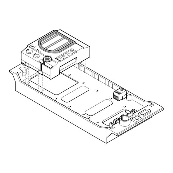
Inserire il gruppo audio-video in alto,
vicino alla testata del telaio (fig. 8-9).
Nel caso di impianti dove può insor-
gere l'effetto Larsen, il microfono può
essere montato in posizione remota,
come indicato nelle figure 10 e 11.
Per scrivere i dati desiderati sul car-
tellino portanome, estrarre il ferma
cartellino e quindi il cartellino (fig. 5).
NOTA. Si possono utilizzare cartellini
portanome personalizzati fino ad un
massimo di 2 mm di spessore.
Effettuare i collegamenti e rimettere la
piastrina fermacavi (fig. 12).
Fissare il telaio alla placca tramite le
due viti in dotazione (fig. 12).
Per montare la placca sulla scatola
incasso avvitare le due viti di fissag-
gio tramite la chiave in dotazione (fig.
1
13).
Caratteristiche tecniche
• Potenza massima commutabile del
microcontatto: 24V 1A.
• Assorbimento del gruppo di illumi-
nazione: 30mA, 17,5V.
• Temperatura di funzionamento: da
-15 °C a +50 °C.
SMALTIMENTO
Assicurarsi che il materiale d'imbal-
laggio non venga disperso nell'am-
biente, ma smaltito seguendo le
norme vigenti nel paese di utilizzo del
prodotto.
Alla fine del ciclo di vita dell'apparec-
chio evitare che lo stesso venga
disperso nell'ambiente.
Lo smaltimento dell'apparecchiatura
deve essere effettuato rispettando le
norme vigenti e privilegiando il rici-
claggio delle sue parti costituenti.
Sui componenti, per cui è previsto lo
smaltimento con riciclaggio, sono
riportati il simbolo e la sigla del mate-
riale.
2
GB INSTALLATION
INSTRUCTIONS
HPC/1÷4 VR ENTRY PANEL
Remove the cable-clamp plate (fig.
6).
Insert the audio module at the top,
near to the top moulding of the chas-
sis (fig. 1-2).
In those installations liable to be affec-
ted by the Larsen effect, the micropho-
ne can be fitted in a remote position,
as indicated in figures 3 and 4.
The name card can be removed and
filled in with the relevant information
by removing the card clip followed by
the actual card itself (fig. 5).
NOTE. Personalized name cards can
be used up to a maximum of 2 mm
thick.
Perform the wiring and refit the cable-
clamp plate (fig. 6).
Secure the chassis to the front plate
using the two screws supplied (fig.
6).
In order to fit the front plate on the
embedding box, screw on the two
fastening screws using the screw-
driver supplied (fig. 7).
Technical features
• Max. switching capacity of the
micro-contact: 24V 1A.
• Current demand of the lighting
module: 30mA, 17.5V.
• Working temperature range: from -15
°C to +50 °C.
HPV/0÷2 VR ENTRY PANEL
Remove the cable-clamp plate (fig.
12).
Insert the audio-video module at the
top, near to the top moulding of the
chassis (fig. 8-9).
In those installations liable to be
affected by the Larsen effect, the
microphone can be fitted in a remote
position, as indicated in figures 10
and 11.
The name card can be removed and
filled in with the relevant information
by removing the card clip followed by
the actual card itself (fig. 5).
NOTE. Personalized name cards can
be used up to a maximum of 2 mm
thick.
Perform the wiring and refit the cable-
clamp plate (fig. 12).
Secure the chassis to the front plate
using the two screws supplied (fig. 12).
In order to fit the front plate on the
embedding box, screw on the two
fastening screws using the screw-
driver supplied (fig. 13).
Technical features
• Max. switching capacity of the
micro-contact: 24V 1A.
• Current demand of the lighting
module: 30mA, 17.5V.
• Working temperature range: from -15
°C to +50 °C.
DISPOSAL
Do not litter the environment with
packing material: make sure it is dis-
posed of according to the regulations
in force in the country where the
product is used.
When the equipment reaches the end
of its life cycle, take measures to
ensure it is not discarded in the envi-
ronment.
The equipment must be disposed of
in compliance with the regulations in
force, recycling its component parts
wherever possible.
1

Verwandte Anleitungen für Bpt HPV/2 VR


Inhaltszusammenfassung für Bpt HPV/2 VR
- Seite 1 HPC/1÷4 VR ISTRUZIONI PER GB INSTALLATION L’INSTALLAZIONE INSTRUCTIONS HPV/0÷2 VR BPT S.p.A. POSTO ESTERNO HPC/1÷4 VR HPC/1÷4 VR ENTRY PANEL 30020 Cinto Caomaggiore Togliere la piastrina fermacavi (fig. 6). Remove the cable-clamp plate (fig. Venezia/Italy Inserire il gruppo audio in alto, vicino alla testata del telaio (fig.
- Seite 2 Components that qualify as recy- Vorschriften des Bestimmungslan- clable waste feature the relevant des ordungsgemäß und umwelt- symbol and the material’s abbre-via- gerecht entsorgt wird. tion. Das nicht mehr benutzbare Gerät ist umweltgerecht zu entsorgen. Die Entsorgung hat den geltenden Vorschriften zu entsprechen und vorzugsweise das Recycling der INSTALLATIONS-...
- Seite 3 • Température de fonctionnement: los dos tornillos incluidos en el sumi- de -15 °C à +50 °C. nistro (fig. 12). Para montar la plancha a la caja hay ELIMINATION que enroscar los dos tornillos de fija- S'assurer que le matériel d’embal- ción con la llave que se entrega junto lage n’est pas abandonné...
- Seite 4 espelho que fixa o letreiro e em Ao fim do ciclo de vida do aparelho seguida o letreiro (fig. 5). evitar que o mesmo seja disperso no NOTA. Podem-se utilizar letreiros ambiente. porta-nome personalizados até um A eliminação da aparelhagem deve máximo de 2 mm de espessura.