Bpt HPC/1 Installationsanleitung
Quicklinks
HPC/1
BPT SpA
30020 Cinto Caomaggiore
Venezia - Italy
03.2004/2403-9311
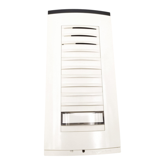
1
1)Placca/Plate/Tableau/Platine/Placa/Placa.
2)Microcontatto/Micro-contact/Mikrokontakt/Micro-
contact/Microcontacto/Micro contacto.
3)Comune chiamata/Common call/Gemeinsamer
Anruf/Appel commun/Común de llamada/Comum
chamada.
ISTRUZIONI
I
PER L'INSTALLAZIONE
POSTO ESTERNO CITOFONICO
VERSIONE DA INCASSO
Inserire il gruppo audio in alto, vicino alla testata del
telaio (fig. 1). Nel caso di impianti dove può insorge-
re l'effetto Larsen, il microfono può essere montato in
posizione remota, come indicato nelle figure 2 e 3.
Applicare il microcontatto (in basso a destra) nell'ap-
posita sede (fig. 4).
ATTENZIONE. La placca é dotata di un comune chia-
mata per i microcontatti, da utilizzare (fig. 5) qualora si
voglia installare altri pulsanti (massimo 4).
Per il montaggio di ulteriori pulsanti seguire le istru-
1
zioni in dotazione agli stessi.
Inserire il gruppo d'illuminazione nell'apposita sede
(fig. 6). Togliere i due bollini di protezione dei fori filet-
tati nella scatola incasso e fissare il telaio tramite le
due viti in dotazione (fig. 8).
Effettuare i collegamenti e bloccare i cavi utilizzando
la piastrina fermacavi (fig. 9). La piastrina va colloca-
ta vicino al gruppo audio.
Per scrivere i dati desiderati sul cartellino portanome,
estrarre il ferma cartellino e quindi il cartellino (fig. 7).
NOTA. Si possono utilizzare cartellini portanome per-
sonalizzati fino ad un massimo di 2 mm di spessore.
Per montare la placca inserire prima la parte superiore
nella testata e quindi, tramite una chiave maschio esa-
gonale s 2,5, avvitare la vite di bloccaggio (fig. 10).
POSTO ESTERNO CITOFONICO
VERSIONE DA PARETE
Inserire il gruppo audio in alto, vicino alla testata della
base (fig. 11). Nel caso di impianti dove può insorge-
re l'effetto Larsen, il microfono può essere montato in
posizione remota, come indicato nelle figure 12 e 13.
Applicare il microcontatto (in basso a destra) nell'ap-
2
posita sede (fig. 14).
ATTENZIONE. La placca é dotata di un comune chia-
mata per i microcontatti, da utilizzare (fig. 15) qualora
si voglia installare altri pulsanti (massimo 4).
Per il montaggio di ulteriori pulsanti seguire le istru-
zioni in dotazione agli stessi. Inserire il gruppo d'illu-
minazione nell'apposita sede (fig. 16).
Effettuare i collegamenti e bloccare i cavi utilizzando
la piastrina fermacavi (fig. 17). La piastrina va collo-
cata vicino al gruppo audio.
Per scrivere i dati desiderati sul cartellino portanome,
estrarre il ferma cartellino e quindi il cartellino (fig. 7).
NOTA. Si possono utilizzare cartellini portanome per-
sonalizzati fino ad un massimo di 2 mm di spessore.
Per montare la placca inserire prima la parte superio-
re nella testata e quindi, tramite una chiave maschio
esagonale s 2,5, avvitare la vite di bloccaggio (fig.
18).
Caratteristiche tecniche
• Potenza massima commutabile del microcontatto:
24V 1A.
• Assorbimento del gruppo di illuminazione: 50mA,
14Vca.
3
• Temperatura di funzionamento: da -15 °C a +50 °C.
2
3
4
4)Gruppo di illuminazione/Lighting module/Beleu-
chtungseinheit/Groupe d'éclairage/Grupo de ilu-
minación/Grupo de iluminação.
5)Piastrina fermacavi/Cable-clamp plate/Kabelhal-
terplättchen/Plaquette serre-câbles/Plaquita suje-
tadora/Braçadeira fixa cabos.
SMALTIMENTO
Assicurarsi che il materiale d'imballaggio non venga
disperso nell'ambiente, ma smaltito seguendo le
norme vigenti nel paese di utilizzo del prodotto.
Alla fine del ciclo di vita dell'apparecchio evitare che
lo stesso venga disperso nell'ambiente.
Lo smaltimento dell'apparecchiatura deve essere
effettuato rispettando le norme vigenti e privilegiando
il riciclaggio delle sue parti costituenti.
Sui componenti, per cui è previsto lo smaltimento con
riciclaggio, sono riportati il simbolo e la sigla del
materiale.
GB INSTALLATION
INSTRUCTIONS
RECESSED AUDIO ENTRY PANEL
Insert the audio module at the top, near to the top
moulding of the chassis (fig. 1). In those installations
liable to be affected by the Larsen effect, the
microphone can be fitted in a remote position, as indi-
cated in figures 2 and 3.
Apply the micro-contact (bottom right) in the relevant
seat (fig. 4).
WARNING: The front plate features a common call for
the micro-contacts, to be used (fig. 5) in the event
other buttons (maximum 4) are to be installed.
In order to fit additional buttons, follow the instructions
supplied with each.
Insert the lighting module in the relevant seat (fig. 6).
Remove the two plugs protecting the threaded holes
in the embedding box and secure the chassis using
the two screws supplied (fig. 8).
Perform the wiring and secure the wires in place
using the cable-clamp plate (fig. 9). The clamp plate
should be located near the audio module.
The name card can be removed and filled in with the
relevant information by removing the card clip fol-
lowed by the actual card itself (fig. 7).
NOTE. Personalized name cards can be used up to
a maximum of 2 mm thick.
In order to fit the front plate, first insert the upper part
in the top moulding and then, using a Allenkey s 2.5,
tighten the lock screw (fig. 10).
SURFACE-MOUNTED AUDIO ENTRY PANEL
Insert the audio module at the top, near to the top
moulding of the base (fig. 11). In those installations
liable to be affected by the Larsen effect, the
microphone can be fitted in a remote position, as indi-
cated in figures 12 and 13.
Apply the micro-contact (bottom right) in the relevant
seat (fig. 14).
WARNING: The front plate features a common call for
the micro-contacts, to be used (fig. 15) in the event
other buttons (maximum 4) are to be installed.
In order to fit additional buttons, follow the instructions
supplied with each.
Insert the lighting module in the relevant seat (fig. 16).
Perform the wiring and secure the wires in place
5
1

Verwandte Anleitungen für Bpt HPC/1


Inhaltszusammenfassung für Bpt HPC/1
- Seite 1 HPC/1 BPT SpA 30020 Cinto Caomaggiore Venezia - Italy 1)Placca/Plate/Tableau/Platine/Placa/Placa. 4)Gruppo di illuminazione/Lighting module/Beleu- 2)Microcontatto/Micro-contact/Mikrokontakt/Micro- chtungseinheit/Groupe d’éclairage/Grupo de ilu- contact/Microcontacto/Micro contacto. minación/Grupo de iluminação. 3)Comune chiamata/Common call/Gemeinsamer 5)Piastrina fermacavi/Cable-clamp plate/Kabelhal- Anruf/Appel commun/Común de llamada/Comum terplättchen/Plaquette serre-câbles/Plaquita suje- chamada. tadora/Braçadeira fixa cabos.
- Seite 2 using the cable-clamp plate (fig. 17). The clamp plate ANMERKUNG. Es können bis zu max. 2 mm dicke should be located near the audio module. Namenskärtchen verwendet werden. The name card can be removed and filled in with the Zur Tableaux-Montage ist zuerst der obere Teil in die relevant information by removing the card clip fol- Stirnseite einzufügen.
- Seite 3 Caractéristique techniques Caractéristicas técnicas • Pouvoir de coupure du micro-contact: 24V 1A • Potencia máxima conmutable del microcontacto: maxi. 24V 1A. • Consommation du groupe d’éclairage: 50mA • Consumo del grupo de iluminación: 50mA 14Vca. 12Vca. • Temperatura de funcionamiento: de -15 °C a +50 °C. •...
- Seite 4 • Consumo do grupo de iluminação: 50mA 14Vca. • Temperatura de funcionamento: de -15 °C a +50 °C. ELIMINAÇÃO Assegurar-se que o material da embalagem não seja disperso no ambiente, mas eliminado seguindo as normas vigentes no país de utilização do produto. Ao fim do ciclo de vida do aparelho evitar que o mesmo seja disperso no ambiente.