V2 CITY11 Bedienungsanleitung
Inhaltsverzeichnis
Verfügbare Sprachen
Verfügbare Sprachen
Quicklinks
Value moves the world
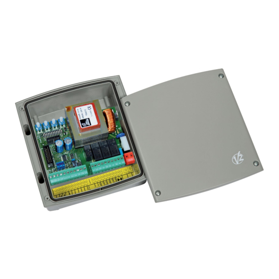
CITY11
CENTRALE DI COMANDO ANALOGICA
I
PER CANCELLI A BATTENTE
ANALOGUE CONTROL UNIT FOR
GB
SWING GATES
ARMOIRE DE COMMANDE ANALOGIQUE
F
POUR PORTAILS BATTANTS
CUADRO DE MANIOBRA ANALÓGICO
E
PARA CANCELAS A BATIENTE
QUADRO DE COMANDO ANALÓGICO
P
PARA PORTÕES DE BATENTE
ANALOGSTEUERUNG FÜR FLÜGELTORE
D
ANALOGE STUURCENTRALE VOOR
NL
HEKKEN MET VLEUGELS
ANALOGOWY PROGRAMATOR DO BRAM
PL
SKRZYDŁOWYCH
IL 353
EDIZ. 20/07/2015
Inhaltsverzeichnis

Verwandte Anleitungen für V2 CITY11


Inhaltszusammenfassung für V2 CITY11
-
Seite 33: Wichtige Hinweise
• Notwendige Vorsichtsmaßnahmen (Beispiel antistatisches 12.30 und von 12.30 bis 18.00 Uhr unter der Nummer Armband) beim Umgang mit Teilen ergreifen, die gegen +39-0172.812411 wenden. elektrostatische Ladungen empfindlich sind. Die Firma V2 behält sich das Recht vor, das Produkt ohne vorherige Ankündigungen abzuändern; die Übernahme der Haftung für Schäden an Personen oder Sachen, die KONFORMITÄTSERKLÄRUNG auf einen unsachgemäßen Gebrauch oder eine fehlerhafte V2 S.p.A. erklärt, dass die CITY11 Produkte mit den wesentlichen Installation zurückzuführen sind, wird abgelehnt. -
Seite 34: Empfindliche Rippen
BESCHREIBUNG DER STEUERUNG FOTOZELLEN Die Steuerung der CITY11 ist ein innovatives V2-Produkt, das Die Steuerung liefert eine 24VAC-Stromversorgung für Fotozellen Sicherheit und Zuverlässigkeit bei der Automation von Flügeltoren mit normal geschlossenem Kontakt und kann vor dem Beginn der garantiert. Toröffnung einen Funktionstest ausführen. Ziel der Planung der CITY11 war es, ein allen Anforderungen gerecht werdendes Produkt in Form einer Steuerung zu schaffen, Für die Fotozelle sind zwei Betriebseinstellungen möglich: die extrem vielseitig ist und alle Voraussetzungen erfüllt, die für 1. Fotozelle immer aktiv: eine funktionale und effiziente Installation erforderlich sind. Das Auslösen der Fotozelle während des Öffnens und • 230V- oder 120V-Versorgung, je nach Modell, für 2 Schließens verursacht den Stop des Tors. Einphasenmotore mit max. 700W. Bei Rückkehr der Fotozelle in den Normalzustand öffnet sich • Ausgang für Elektroschloss zu 12V. das Tor vollständig. • Eingang für Schlüsselwählschalter oder Druckknopf. 2. Fotozelle NICHT aktiv beim Öffnen: • Eingang für Sicherheitsfotozelle. - Seite 35 START FUSSGÄNGER ACHTUNG: der Rippenfunktionstest ist den Start Fußgänger verursacht bei geschlossenem Tor ein teilweises herkömmlichen Rippen vorbehalten (wenn diese mit einer Öffnen (ca. die Hälfte der Toröffnung) nur des an Motor 1 entsprechenden Steuerung ausgestattet sind). angeschlossenen Torflügels. Nachfolgende Befehle für Start Fußgänger funktionieren entsprechend der schrittweisen Logik. Die Testfunktion NICHT aktivieren, wenn Rippen aus leitendem Gummi oder herkömmliche Rippen verwendet Während eines Fußgängerzyklus verursacht der Startbefehl die werden, die mit einer entsprechenden Steuerung zur vollständige Öffnung beider Torflügel.
-
Seite 36: Elektrische Anschlüsse
ELEKTRISCHE ANSCHLÜSSE POWER WORK PAUSE DELAY 1 2 3 4 5 6 7 8 9 10 11 12 mains overload START STOP EDGE START P. PHOTO L1 L2 L3 L4 L5 L6 L7 L8 L9 L10 L11 K1 K2 K3 K4 K5 K6 K7 K8 K9 K10 N mains L Antennensteuerung K1 - K2... -
Seite 37: Montage Der Kabeldurchgänge
EINSTELLUNG DER LEISTUNG UND DER MONTAGE DER KABELDURCHGÄNGE Die Box ist zur Montage von 4 Kabeldurchgängen an den BETRIEBSZEITEN speziellen Punkten zum Herausbrechen vorgesehen. Der Typ des Leistung und Betriebszeiten sind mittels 4 an der Steuerung Kabeldurchgangs ist in der Abbildung dargestellt. vorhandenen Trimmern einstellbar: ACHTUNG: ACHTUNG: es wird empfohlen, die Einstellung der • Vor dem Lichen der Box die elektronische Platine abmontieren. Betriebszeit bei deaktivierter Verlangsamungsfunktion (DIP 5 OFF) vorzunehmen. • Die Box mit einer für die Abmessungen des Kabeldurchgangs angemessenen Fräse lochen. ACHTUNG: die Einstellung der Zeiten muss • Kabeldurchgänge mit den vorgesehenen Muttern befestigen. -
Seite 38: Programmierung Der Betriebslogik
PROGRAMMIERUNG DER BETRIEBSLOGIK Man kann unterschiedliche Betriebslogiken der Steuerung erhalten, indem man einfach die sich auf der Platine befindenden Dip-Switchs betätigt. Nachfolgend sind die jedem einzelnen Dip-Switch zugeordneten Funktionen aufgeführt. DIP FUNKTION EINSTELLUNG BESCHREIBUNG Das Blinklicht leuchtet für 3 s auf, bevor die Motoren gestartet werden (Öffnungsphase) . Aktivierte Vorblitz, 1 s nach dem Vorblitz wird der Wasserschlag für 2 s aktiviert. Nach 0,5 s des Wasserschlags Funktionen Wasserschlag, wird das Elektroschloss aktiviert. Vorzeit des Vorblitz deaktivert. Wasserschlag deaktiviert. Elektroschlosses 0,3 s Vorzeit des Elektroschlosses Das Tor wird automatisch nach der mit dem PAUSEN-Trimmer eingestellten Zeit Aktiviert geschlossen Automatisches Schließen Das Tor bleibt nach der Öffnungsphase geöffnet. Der Schließbefehl muss mit einem Deaktiviert anderen START-Befehl erteilt werden Ein START-Befehl wird während der Öffnungsphase nicht wahrgenommen Nicht akzeptiert Start beim Öffnen Ein START-Befehl wird während der Öffnungsphase akzeptiert Akzeptiert Start während des Öffnens verursacht Schließen.