Herunterladen Inhalt Inhalt Diese Seite drucken
V2 PD5 Handbuch

V2 PD5 Handbuch

Digitale steuerzentrale für flügeltoren
Vorschau ausblenden Andere Handbücher für PD5:
Inhaltsverzeichnis

Werbung

Verfügbare Sprachen
  • DE

Verfügbare Sprachen

  • DEUTSCH, seite 71
PD5 / PD5-120V / PD7 / PD7-120V
CENTRALE DI COMANDO DIGITALE PER CANCELLI A BATTENTE 230V / 120V
I
GB
DIGITAL CONTROL UNITS FOR SWING GATES (230V / 120V)
ARMOIRE DE COMMANDE DIGITALE POUR PORTAILS A BATTANT 230V /120V
F
D
DIGITALE STEUERZENTRALE FÜR FLÜGELTOREN (230V / 120V)
CUADRO DE MANIOBRAS DIGITAL PARA CANCELAS BATIENTES 230V / 120V
E
V2 ELETTRONICA SPA
Corso Principi di Piemonte, 65 / 67
12035 RACCONIGI (CN) ITALY
tel. +39 01 72 81 24 11
info@v2elettronica.com
IL n.020
EDIZ. 18/04/2005
fax +39 01 72 84 050
www.v2elettronica.com

Werbung

Inhaltsverzeichnis
loading

Inhaltszusammenfassung für V2 PD5

  • Seite 1 IL n.020 EDIZ. 18/04/2005 PD5 / PD5-120V / PD7 / PD7-120V CENTRALE DI COMANDO DIGITALE PER CANCELLI A BATTENTE 230V / 120V DIGITAL CONTROL UNITS FOR SWING GATES (230V / 120V) ARMOIRE DE COMMANDE DIGITALE POUR PORTAILS A BATTANT 230V /120V DIGITALE STEUERZENTRALE FÜR FLÜGELTOREN (230V / 120V)
  • Seite 3 PD5 / PD5-120V / PD7 / PD7-120V ISTRUZIONI ..........1 INSTRUCTIONS .
  • Seite 5: Inhaltsverzeichnis

    TABELLA FUNZIONI PD5 - PD7 ........
  • Seite 6: Avvertenze

    (collegato all’ingresso La centrale di comando PD5 - PD7 è destinata al STOP della scheda di comando) in modo che comando di uno o due attuatori elettromeccanici sia possibile l’arresto immediato del cancello per l'automazione di porte e cancelli a battente.
  • Seite 7: Descrizione Della Centrale

    Porre la massima attenzione al un'installazione funzionale ed efficiente. verso di innesto dei moduli estraibili. La PD5 - PD7 è dotata di un display il quale permette, oltre che una facile programmazione, il INNESTO MODULO RICEVITORE costante monitoraggio dello stato degli ingressi;...
  • Seite 8: Pannello Di Controllo

    UP e DOWN. PROGRAMMAZIONE • Premendo il tasto UP si scorre all’interno del La centrale PD5 - PD7 presenta una struttura di menù funzioni dal basso verso l’alto. programmazione a menù, ognuno dei quali •...
  • Seite 9: Caratteristiche Tecniche

    INTERPRETAZIONE DELLA È possibile definire il funzionamento della centrale PD5 - PD7 con due diverse modalità di LAMPADA SPIA (WARNING LIGHT) programmazione: PROGRAMMAZIONE PREDEFINITA (DEFAULT) La lampada spia (warning light), quando installata o PROGRAMMAZIONE PERSONALIZZATA. indica in tempo reale lo stato del cancello, il tipo...
  • Seite 10: Collegamenti Alla Morsettiera

    COLLEGAMENTI ALLA MORSETTIERA ATTENZIONE: si consiglia di utilizzare l'antenna esterna modello ANS433 o ANSGP433 per garantire la massima portata radio. 13.-14. Elettroserratura 12VAC Centrale antenna 14.-15. Lampada spia 24VAC - 3W Schermatura antenna 16.-17. Luce di cortesia 230V / 120V - 10A Comando di apertura per il collegamento di dispositivi tradizionali 18.-19.
  • Seite 11: Programmazione Standard (Default)

    Questo tipo di programmazione permette di caricare in memoria i dati di Default V2: i dati sono indicati nella tabella riassuntiva allegata al fondo (colonna DATI DI DEFAULT a pag. 21). Selezionare l'opzione desiderata tramite i tasti UP e DOWN, quindi premere MENU per confermare.
  • Seite 12: Tempo Chiusura Anta 1

    TEMPO CHIUSURA ANTA 1 Questo menù è regolabile da 0 a 120 secondi (±0,5) e determina il tempo per cui l’anta 1 si chiude. Per evitare che l’anta non si chiuda completamente, è consigliabile impostare un tempo più lungo (almeno di 1 sec.) di quello di apertura t.AP1.
  • Seite 13: Ritardo D'anta In Apertura

    RITARDO D’ANTA IN APERTURA Per evitare che le ante possano entrare in collisione durante l’apertura, è necessario introdurre il tempo di ritardo r.AP, regolabile da 0 a 120 secondi (±0,5). In questo modo l’apertura dell’anta 2 viene ritardata rispetto all’anta 1 del tempo impostato. RITARDO D’ANTA IN CHIUSURA Per evitare che le ante possano entrare in collisione o sovrapporsi durante la chiusura, è...
  • Seite 14: Tempo Colpo D'ariete

    Successivamente impostare il tempo di rallentamento (ad esempio 4.5 o 6 s). TEMPO CHIUSURA VELOCE DOPO RALLENTAMENTO IN CHIUSURA (solo PD5) Qualora venga impostato un tempo di rallentamento diverso da 0, è possibile che la velocità del cancello non sia sufficiente a far scattare la serratura durante la chiusura.
  • Seite 15: Potenza Dei Motori

    POTENZA DEI MOTORI Questo menù permette la regolazione della potenza dei motori da 30 a 100% con scansione ±5. SPUNTO Quando il cancello è fermo e si appresta ad entrare in movimento, viene contrastato dall'inerzia iniziale, di conseguenza se il cancello è molto pesante c'è il rischio che le ante non si muovano.
  • Seite 16: Start In Pausa

    START IN PAUSA Questo menù permette di selezionare le funzioni del comando di START durante la fase di pausa. ChiU il comando di START richiude il cancello. il comando di START non è sentito. Questa funzione non deve essere selezionata quando la chiusura automatica non è...
  • Seite 17: Chiusura Automatica

    CHIUSURA AUTOMATICA Permette la selezione tra funzionamento semiautomatico o automatico. Con il funzionamento semiautomatico il comando di START o START PEDONALE apre il cancello, ad apertura ultimata il cancello rimane fermo fino al successivo comando di apertura, che richiude. Diversamente, in modo automatico il comando di START o START PEDONALE inizia un ciclo: il cancello apre per il...
  • Seite 18: Luci Di Cortesia

    LUCI DI CORTESIA (solo PD5) Grazie all’uscita COURTESY LIGHT la centrale PD5 permette il collegamento di un utilizzatore (ad esempio la luce di cortesia o le luci da giardino), che viene comandato in modo automatico o tramite azionamento dall’apposito tasto trasmettitore.
  • Seite 19: Funzione Timer

    è attiva con un tempo aggiunto, in apertura o in chiusura, regolabile da 0 a 120 secondi.(±0,5) FUNZIONE DELL'INGRESSO START La centrale PD5 - PD7 oltre a permettere il collegamento dei tradizionali dispositivi di comando con contatto N.A., consente l'utilizzo del SELETTORE DIGITALE modello TTNC e del LETTORE DI PROSSIMITÀ...
  • Seite 20: Funzione Dell'ingresso Di Start Pedonale

    FUNZIONE DELL'INGRESSO START PEDONALE Come la precedente funzione, ma il collegamento del SELETTORE DIGITALE modello TTNC e del LETTORE DI PROSSIMITÀ modello VRD è fatto sull'ingresso di START PEDONALE. Cont l'ingresso START PEDONALE è abilitato per il collegamento di dispositivi tradizionali di comando con contatto N.A.
  • Seite 21: Ingresso Foto 1

    INGRESSO FOTO 1 (FOTOCELLULA INTERNA) Questo ingresso può essere abilitato per il collegamento di due sicurezze diverse: la fotocellula o la costa. La costa (contatto normalmente chiuso) è una sicurezza attiva in apertura e in chiusura (non attiva durante il colpo di ariete): il suo intervento durante l'apertura ferma il cancello, inverte il moto per 4 sec.
  • Seite 22: Modalità Rolling Code

    START PEDONALE. tEL3 STOP: trasmettendo il codice associato a tEL3, la centrale riceve un comando di STOP. tEL4 LUCI DI CORTESIA (solo PD5): trasmettendo il codice associato a tEL4, la centrale attiva l’uscita LUCI DI CORTESIA.
  • Seite 24: Inserimento In Memoria Dei Codici Desiderati

    (da 000 a 317 con modulo MEM200; da 000 a 999 con modulo MEM1000, solo PD5). I puntini della seconda e terza cifra indicano lo stato della zona di memoria: i puntini sono accesi se la zona di memoria selezionata è occupata, invece sono spenti se la zona di memoria è libera.
  • Seite 25: Tabella Funzioni Pd5 - Pd7

    0 ÷ 120 s Tempo rallentamento (solo PD5) t.CvE 0 ÷ 120 s Tempo chiusura veloce dopo rallentamento in chiusura (solo PD5) Pot. 30 ÷ 100% Potenza motori % SPUn no / Si Avvio dei motori al massimo della potenza St.AP...
  • Seite 26 Ingresso radio associato al comando START tEL 2 Ingresso radio associato al comando START PEDONALE tEL 3 Ingresso radio associato al comando STOP tEL 4 Ingresso radio associato alle luci di cortesia (solo PD5) Fine no / Si Fine programmazione...
  • Seite 27 FUNCTION TABLE PD5 - PD7 ........
  • Seite 28: Important Remarks

    • Always remember to connect the earth according to current standards (EN 60335-1, The PD5 - PD7 control unit can drive one or more EN 60204-1). electromechanical actuators for the automation of swing doors and swing gates. Any other utilization is not in specification.
  • Seite 29: Description Of The Control Unit

    DESCRIPTION OF THE CONTROL UNIT ATTENTION: it is necessary to turn off The digital control unit PD5 - PD7 is an innovative the control unit power before doing the V2 ELETTRONICA product that guarantees a operations mentioned here below. Please pay...
  • Seite 30: Control Panel

    On the other side, the function menu are used to activate the required functions (e.g. timed lights, The PD5 - PD7 unit can be set up in two different PHOTO1 active as a travelling edge, PHOTO2 program modes: DEFAULT PROGRAM MODE or inactive, etc.).
  • Seite 31: Warning Light Description

    MENU key the number 7.0 will be dispayed. Increase the number pressing UP or DOWN. Press MENU to display function t.ChP again. TECHNICAL SPECIFICATIONS Model PD5-120V PD7-120V Power supply 230VAC - 50Hz 120VAC - 60Hz 230VAC - 50Hz...
  • Seite 32: Terminal Connections

    TERMINAL CONNECTION WARNING: we suggest to use the external aerial (model ANS433 or ANSGP433) in order to guarantee the maximal range. 13.-14. Electric lock 12 VAC Antenna 14.-15. Warning light 24 VAC - 3W Antenna shield. 16.-17. Courtesy light 230V / 120V - 10A Opening control for the connection of control devices with N.O.
  • Seite 33: Standard Programming (Default)

    This type of programming allows loading the V2 ELETTRONICA default program in the memory: the standard data that will be inserted automatically are shown in the table below (in the column DEFAULT DATA on pag. 43). Set the wished function pressing the up or DOWN keys and press MENU key to confirm.
  • Seite 34: Closing Time Gate 1

    CLOSING TIME GATE 1 This menu is adjustable from 0 to 120 seconds (±0,5) which is the closing time for gate 1.To avoid the uncompleted closing of the gate, we suggest to set a longer opening time of t.AP1. CLOSING TIME GATE 2 This menu is adjustable from 0 to 120 seconds (±0.5) which is the closing time for gate 2.
  • Seite 35: Gate Delay During Opening

    GATE DELAY DURING OPENING In order to avoid any collision of the gate during the opening phase, the time of delay should be introduced r.AP, which is adjustable from 0 to 120 seconds (±0,5) .In such a case the opening time of gate 2 is delayed in comparison to the gate 1.
  • Seite 36: Backlash Time

    0 to 120 seconds (± 0,5). SLOWING DOWN TIME (Pd5 only) This menu permits the activation of the gate slowing down function for a time to be set between 0 and 120 s(±...
  • Seite 37: Motor Power

    MOTOR POWER This menu permits to adjust the motor power from 30 to 100% with a scanning of ±0,5. START OFF When the gate is at a standstill and is going to move, it is contrasted by the starting inertia. As a consequence of this, if the gate is very heavy the gates might not move.
  • Seite 38: Start In Pause

    START IN PAUSE This menu permits to select the functions of the command start during the standstill. ChiU the command START closes the gate. the command START is not available. This function cannot be selected until the automatic closing has been activated (menu Ch.AU).
  • Seite 39: Automatic Closing

    AUTOMATIC CLOSING Permits the selection between the semiautomatic or automatic functioning. By the semiautomatic functioning the command of START or PEDESTRIAN START opens the gate, when the opening is complete the gate remains still until the successive command of opening, which will reclose it.
  • Seite 40: Flashlight In Pause

    COURTESY LIGHTS (PD5 only) Thanks to the connection "courtesy light" the PD5 - PD7 control unit enables the connection of the courtesy lights (I.E. garden lights), which can work automatically (lights on for the whole cycle) or timed (lights on for a time adjustable from 0 to 999 seconds).
  • Seite 41: Timer Function

    START INPUT FUNCTION Besides enabling connection of control devices with normally open contact, the PD5 - PD7 station allows to employ a WIRED DIGITAL SELECTOR (TTNC) and a IDENTIFICATION UNIT (VRD). By selecting the Cod option, it is possible to...
  • Seite 42: Pedestrian Start Input Function

    PEDESTRIAN START INPUT FUNCTION This is the same as the preceding function, but the connection with the WIRED DIGITAL SELECTOR (TTNC) or the IDENTIFICATION UNIT (VRD) is made on the PEDESTRIAN START input. Cont the PEDESTRIAN START input is enabled for the connection of control devices with normally open contact.
  • Seite 43: Input Photo 1

    INPUT PHOTO 1 (INTERNAL PHOTOCELLS) This input can be activated for the connection of two different safety devices: the photocell or the rib. The rib (contact normally closed) is an active safety device in opening and closing (now active during the backlash): its intervention during the opening phase stops the gate, inverts the motion for 4 s, without offsetting the doors.
  • Seite 44: Rolling Code Mode

    PEDESTRIAN START tEL3 STOP: transmitting the code associated to tEL3, the control unit receives a STOP tEL4 COURTESY LIGHTS (PD5 only) : transmitting the code associated to tEL4, the control unit activates the COURTESY LIGHTS output.
  • Seite 46: Storing New Codes

    (from 000 to 317 with module MEM200; from 000 to 999 with module MEM1000, PD5 only). The dots after the second and the third digits show the status of the zone of memory: they are on if the selected zone is busy, and off if the zone is free.
  • Seite 47: Function Table Pd5 - Pd7

    Pre-flashing time t.rAL 0 ÷ 120 s Slowing down time (PD5 only) t.CvE 0 ÷ 120 s Fast closing time after slowing down during closing (PD5 only) Pot. 30 ÷ 100% Motor power SPUn no / Si Start off St.AP...
  • Seite 48 Radio input associated to START command tEL 2 Radio input associated to Ped. START command tEL 3 Radio input associated to STOP command tEL 4 Radio input associated to courtesy light (PD5 only) Fine no / Si End of programming...
  • Seite 49 TABLEAU FONCTIONS PD5 - PD7 ........
  • Seite 50: Conseils Importants

    CONFORMITÉ AUX NORMATIFS EN 60204-1 (Sécutité de la machinerie. V2 ELETTRONICA SPA déclare que la centrale Équipement électriquedes machines, PD5 - PD7 est conforme aux qualités requises partie 1: régles générales). par les Directives: 93/68/EEC, 73/23/EEC Ils ont EN 12445 (Sécutité...
  • Seite 51: Description De La Centrale

    V2 ELETTRONICA, qui garantit sécurité superhétérodyne de haute sensibilité. et fiabilité pour l'automation de portails à un ou à deux volets. La conception de projet de la PD5 - PD7 a visé réalisation d'un produit qui soit en ATTENTION: Avant de faire ces mesure de correspondre à...
  • Seite 52: Panneau De Contrôle

    DOWN. PROGRAMMATION • En appuyant sur la touche UP l'on défile à La centrale PD5 - PD7 présente une structure de l'intérieur du menu fonctions de bas en haut. programmation par menus, chacun desquels • En appuyant sur la touche DOWN l'on défile à...
  • Seite 53: Interpretation Du Voyant (Warning Light)

    éteinte Dans les pages suivantes se trouve le diagramme EN PAUSE la lumière est toujours allumée des fonctions de la PD5 - PD7 et sa description. EN OUVERTURE la lumière clignote lentement (2Hz) Pour lire le diagramme suivre les instructions EN FERMETURE la lumière clignote...
  • Seite 54: Branchements Au Borniere

    BRANCHEMENTS AU BORNIERE ATTENTION: on conseille d'utiliser l'antenne externe model ANS433 ou ANSGP433 pour pouvoir garantir la portée maximal 13.-14. Electro-blockage 12VAC Centrale antenne Blindage antenne 14.-15. Voyant 24VAC - 3W Commande d'ouverture pour le 16.-17. Lumière de service 230V /120V - 10A branchement de: commande 18.-19.
  • Seite 55: Programmation Predefinie (Default)

    Ce type de programmation permet de charger dans la mémoire le programme de Default prédéfini par V2 ELETTRONICA: les données standard qui seront insérés automatiquement sont indiquées sur le tableau récapitulatif ci-dessous (colonne DONNÉES DE DEFAULT). Appuyer sur la touche UP ou DOWN pour sélectionner la fonction désirée et appuyer sur la...
  • Seite 56: Duree De Fermeture Du Battant 1

    DUREE DE FERMETURE DU BATTANT 1 Permet un réglage de 0 à 120 secondes (±0,5) de la durée nécessaire à la fermeture du battant 1. Pour éviter que le battant ne reste ouvert, il est conseillé d'insérer une durée plus élevée que celle de l'ouverture t.AP1.
  • Seite 57: Delai Du Battant Pendant La Phase D'ouverture

    DELAI DU BATTANT PENDANT LA PHASE D'OUVERTURE Pour éviter que les battant n'entrent en collision pendant l'ouverture, il est nécessaire d'introduire le délai r.AP, réglable de 0 a 120 secondes (±0,5). De cette manière l'ouverture du battant 2 est retardée contrairement à...
  • Seite 58: Duree Coups De Belier

    à l'ouverture qu'à la fermeture : la durée de pré- clignotement est réglable de 0 a 120 secondes ±0,5. TEMPS DE RALENTISSEMENT (seul PD5) Ce menu permet de conférer la fonction de ralentissement du portail pour un temps établi entre 0 et 120 seconde (±1,5 s).
  • Seite 59: Puissance Des Moteurs

    PUISSANCE DES MOTEURS Ce menu permet de régler la puissance des moteurs de 30 a 100 % avec scansion ±5. DEMARRAGE RAPIDE Quand le portail est arrêté et s'apprête à entrer en mouvement, il entre en opposition avec l'inertie initiale, par conséquent, si le portail est très lourd, il existe un risque que les battants ne bougent pas.
  • Seite 60: Demarrage En Pause

    DEMARRAGE EN PAUSE Ce menu permet de sélectionner les fonctions de la commande de démarrage pendant la phase de pause. ChiU la commande de démarrage referme le portail. la commande de démarrage n'est pas captée. Cette fonction ne doit pas entre sélectionne quand la fermeture automatique n'est pas activée menu Ch.AU.
  • Seite 61: Fermeture Automatique

    FERMETURE AUTOMATIQUE Elle permet de choisir entre fonctionnement semi-automatique et automatique. Avec le fonctionnement semi-automatique, la commande de démarrage ou de démarrage piéton ouvre le portail; lorsque l'ouverture est complète, le portail reste ouvert jusqu'à la commande d'ouverture suivante qui le referme. En mode automatique, en revanche, la commande de démarrage ou de démarrage...
  • Seite 62: Clignotant En Pause

    LUMIERES DE SERVICE (seul PD5) Grâce à la sortie "courtesy light" la centrale PD5 permet de brancher des points lumineux (ex: lumières de jardin ou lumière de service), qui peuvent fonctionner de façon automatique ou de façon émetteur. Dans le premier cas, la fermeture du contact N.A. est rendue possible grâce à une commande de démarrage ou de démarrage piéton (aussi bien avec clé...
  • Seite 63: Fonction Timer

    0 a 120 secondes. FONCTION DE L' ENTRÉE START La centrale PD5 - PD7 en plus de permettre le raccordement des dispositifs de commande traditionnels avec contact normalement ouvert, permet l'utilisation du CLAVIER CABLE (TTNC) et du LECTEUR DE PROXIMITE (VRD).
  • Seite 64: Fonction De L'entrée Start Piétonnier

    FONCTION DE L'ENTRÉE START PIÉTONNIER Comme la précédente fonction, mais le raccordement du sélecteur électronique à clavier numérique ou du récepteur RÉPONDEUR se fait sur l'entrée de START PIÉTONNIER. l'entrée START PIÉTONNIER est autorisée pour le raccordement du clavier câblé (TTNC) ou le lecteur de proximité...
  • Seite 65: Entree Cellule 1

    ENTREE CELLULE 1 (PHOTOCELLULES INTERNE) Cette entrée peut être activée pour le branchement de deux sécurités différentes: la photocéllule ou la cellule mobile. La cellule mobile (contact norm. fermé) est une sécurité active en ouverture et en fermeture (inactive pendant le coups du bélier): son intervention pendant l'ouverture immobilise le portail, inverti le mouvement sans décalage des battants.
  • Seite 66: Modalité Rolling Code

    STOP: avec la transmission du code associé à tEL3, la centrale reçoit une commande de STOP. tEL4 SORTIE LUMIERES DE SERVICE (seul PD5) : avec la transmission du code associé à tEL4, la centrale active la sortie LUMIERES DE...
  • Seite 68: Insertion Dans La Memoire Des Codes Souhaités

    (de 000 à 317 avec module MEM200; de 000 à 999 avec module MEM1000, seul PD5). Les petits points du deuxième et du troisième chiffre signalent l'état de la zone de mémoire: les petits points sont allumés si la zone de mémoire sélectionnée est occupée, ils sont éteints par contre si la zone de mémoire est libre.
  • Seite 69: Tableau Fonctions Pd5 - Pd7

    Durée pré- clignotement t.rAL 0 ÷ 120 s Durée de ralentissement (seul PD5) t.CvE 0 ÷ 120 s Durée fermeture rapide après ralentissement en fermeture (seul PD5) 0.0 Pot. 30 ÷ 100% Puissance moteur SPUn no / Si Démarrage rapide St.AP...
  • Seite 70 Entrée radio associée à la commande START tEL 2 Entrée radio associée à la commande START P. tEL 3 Entrée radio associée à la commande STOP tEL 4 Entrée radio associée aux lumières de service (seul PD5) Fine no / Si Fin programmation...
  • Seite 71 FUNKTIONSÜBERSICHT PD5 - PD7 ........
  • Seite 72: Wichtige Hinweise

    NORMEN EN 12453 (Nutzungssicherheit kraftbetätigter Die V2 ELETTRONICA SPA erklärt die EC- Tore Anforderungen) Konformität der Steuerung PD5 - PD7 mit der durch die EG-Richtlinie 93/68/EEC, 73/23/EEC, • Der Installateur muss eine Vorrichtung (z.B. festgelegten wesentlichen Erfordernissen. Für die thermomagn. Schalter) anbringen, die die Konformität-skontrolle wurden die folgenden...
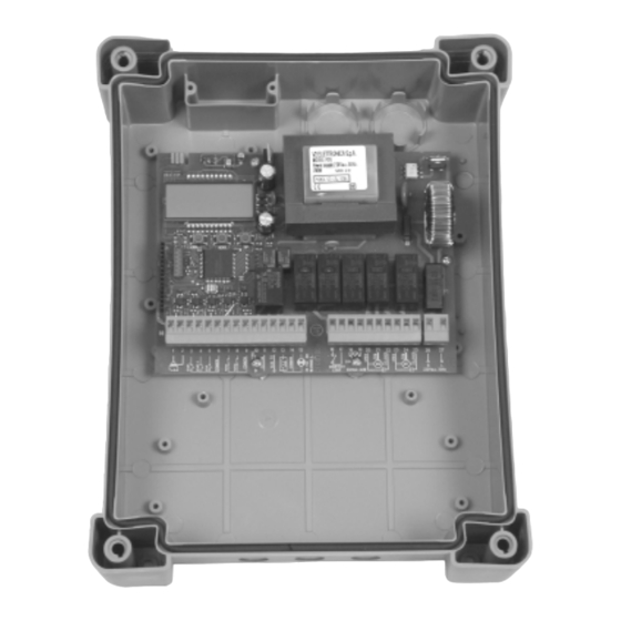
  • Seite 73: Beschreibung Der Steuerzentrale

    Das Vorhandensein einer Buchse mit chnellsteckverbindung gestattet den Anschluss STEUERZENTRALE eines Empfängermoduls der Serie MT433 mit Die digitale Zentrale PD5 - PD7 ist ein innovatives hochsensiblem Überlagerungsempfang. Produkt der V2 ELETTRONICA, welches Sicherheit und Zuverlässigkeit für die Automatisierung von Toren mit einem oder zwei Flügeln garantiert.
  • Seite 74: Steuertafel

    Menü vor oder zurück PROGRAMMIERUNG bewegen (für einen schnellen Vorlauf halten Sie Die Zentrale PD5 - PD7 ermöglicht die bitte die Taste gedrückt). Drücken Sie die Taste Programmierung mit Menüstruktur, wobei jedes MENÜ, um auf die jeweiligen Einstellungen Menü...
  • Seite 75: Interpretation Der Leuchtanzeige (Warning Light)

    Weise kann der Installateur die Prüfung und an, durch die Art des jeweiligen Blinksignals Feinregulierung vornehmen. werden die vier verschiedenen Zustände unterschieden: Die Funktion der Zentrale PD5 - PD7 kann in zwei verschiedenen Modalitäten definiert werden: STOP Anzeige ausgeschaltet VOREINGESTELLTE PROGRAMMIERUNG...
  • Seite 76: Anschlüsse Am Klemmenbrett

    ANSCHLÜSSE AM KLEMMENBRETT ACHTUNG: um die maximale Funkübertragung zu versichern, ist es ratsam, die äußere Antenne ANS433 und ANSGP433 zu benutzen. 13.-14. Elektrosperre 12 VAC Zentrale Antenne. 14.-15. Leuchtanzeige 24VAC - 3W Entstörung Antenne. Öffnungsbefehl für die Anschlüsse der Kontakt für Beleuchtung 230V / 120V - 16.-17.
  • Seite 77: Voreingestellte Programmierung (Default)

    Diese Art der Programmierung gestattet, das vordefinierte Programm der V2 ELETTRONICA in den Speicher zu laden: Die automatisch eingegebenen Standarddaten sind in der zusammenfassenden Übersicht in der Anlage unten aufgezählt (Spalte DEFAULT-DATEN). • Drücken Sie die Taste MENU, auf dem Display erscheint no.
  • Seite 78: Zeit Des Schliessens Flügel 1

    ZEIT DES SCHLIESSENS FLÜGEL 1 Dieser Wert ist von 0 bis 120 Sekunden einstellbar (±0,5) und bestimmt die Zeit in der sich der Flügel 1 schließt. Um zu verhindern, dass der Flügel nicht vollständig schließt, sollte die eingestellte Zeit länger als die der Öffnung t.AP1 sein. ZEIT DES SCHLIESSENS FLÜGEL 2 Dieser Wert ist von 0 bis 120 Sekunden einstellbar (±0,5) und bestimmt die Zeit, in der sich der Flügel...
  • Seite 79: Verzögerung Des Flügels Beim Öffnen

    VERZÖGERUNG DES FLÜGELS BEIM ÖFFNEN Um ein Zusammenstoßen der Flügel in der Öffnungsphase zu vermeiden, ist die Verzögerungszeit r.AP einzustellen. Der Wert ist von 0 bis 120 Sekunden (±0,5) regulierbar. Auf diese Weise wird die Öffnung von Flügel 2 im Vergleich zu Flügel 1 um die eingestellte Zeit verzögert.
  • Seite 80: Zeiteinstellung Widderstoss

    öffnet und schließt. Anschließend stellen Sie die Bremszeit ein (zum Beispiel 5 oder 6 Sekunden). ZEIT FÜR SCHNELLES SCHLIESSEN NACH DEM BREMSEN IN DER SCHLIESSPHASE (nur PD5) Wird eine Bremszeit mit einem Wert ≠ 0 eingestellt, könnte die Geschwindigkeit des Tores u.U. nicht ausreichend sein, um die Sperre beim Schließen...
  • Seite 81: Motorenleistung

    MOTORENLEISTUNG Dieses Menü gestattet die Regulierung der Motorleistung von 30 bis 100% mit einem Takt von ±5 %. ANLAUF Beim Übergang des Tores vom Stillstand zur Bewegung muss eine gewisse Anfangsträgheit überwunden werden. Ist das Tor sehr schwer, kann dies dazu führen, dass die Bewegung nicht möglich ist.
  • Seite 82: Start Im Modus Pause

    START IM MODUS PAUSE Mithilfe dieses Menüs können die Funktionen des Befehls START im Modus Pause festgelegt werden. ChiU der Befehl START schließt das Tor. der Befehl START wird ignoriert. Diese Einstellung darf nicht ausgewählt werden, wenn die Funktion des automatischen Schließens nicht aktiv ist (Menü...
  • Seite 83: Automatisches Schliessen

    AUTOMATISCHES SCHLIESSEN Diese Funktion gestattet die Auswahl zwischen halb und vollautomatischem Arbeitsmodus. Im halbautomatischen Modus verursacht der Befehl START oder START FUSSGÄNGER die Öffnung des Tors, nach vollständiger Öffnung bleibt das Tor unbeweglich bis zum nächsten Startbefehl, der es wieder schließt. Im vollautomatischen Modus beginnt mit dem Befehl START oder START FUSSGÄNGER ein...
  • Seite 84: Beleuchtung

    BELEUCHTUNG (nur PD5) Der Ausgang COURTESY LIGHT der Zentrale PD5 gestattet den Anschluss einer Zusatzanwendung (zum Beispiel die Beleuchtung der Auffahrt oder des Gartens) die automatisch durch Druck auf die dafür vorgesehene Taste auf der Fernbedienung aktiviert wird. Im ersten Fall kann das Schließen des Kontaktes N.a. durch den Befehl START oder START FUSSGÄNGER (sowohl mittels Schlüssel, als auch mit der Fernbedienung) erfolgen.
  • Seite 85: Timer

    Zusatzzeit in der Öffnungs- oder Schließphase aktiv. FUNKTION DES EINGANGS START Außer der Nutzung traditioneller Steuervorrichtungen mit Öffnungskontakt, gestattet die Zentrale PD5 - PD7 die Befehlsgebung über verkabelter Digitalwähler (TTNC) und über ein einer Identifikationseinheit (VRD). Mit Aktivierung der Option Cod kann die elektronische Steuervorrichtung mit TTNC (verkabelter Digitalwähler) oder VRD (Identifikationseinheit) an den...
  • Seite 86: Funktion Des Eingangs Start Fussgängerdurchgang

    FUNKTION DES EINGANGS START FUSSGÄNGERDURCHGANG Die Funktion entspricht der oben beschriebenen, mit dem Unterschied, dass der Anschluss des elektronischen Wählers über VERKABELTER DIGITALWÄHLER (TTNC) oder des IDENTIFIKATIONSEINHEIT (VRD) am Eingang START FUSSGÄNGERDURCHGANG erfolgt. der Eingang START ist vorbereitet für den Anschluss des verkabelteren Digitalwählers (TTNC) oder der Identifikationseinheit (VRD).
  • Seite 87: Eingang Foto 1

    EINGANG FOTO 1 (INNENFOTOZELLEN) Dieser Eingang kann für den Anschluss von zwei verschiedenen Sicherheitsfunktionen verwendet werden: Eine Fotozelle oder Lichtschranke. Die Lichtschranke (Kontakt i.d.R. geschlossen) ist eine Sicherheitsfunktion, die während der Öffnungs und Schließphase des Tores aktiv ist (nicht aktiv beim Widderstoß): Bei Signalempfang in der Öffnungsphase wird das Tor gestoppt und die Laufrichtung der Motoren für eine Dauer von 4...
  • Seite 88: Modus Rolling Code

    Befehl an tEL2 übertragen, empfängt die Zentrale einen Befehl START FUSSGÄNGER. tEL3 STOP: Wird der zugehörige Befehl an tEL3 übertragen empfängt die Zentrale einen Befehl STOP. tEL4 BELEUCHTUNG (nur PD5): Wird der zugehörige Befehl an tEL4 übertragen, aktiviert die Zentrale den Ausgang BELEUCHTUNG.
  • Seite 90: Eingabe Der Gewünschten Codes In Den Speicher

    Speicherposition (von 000 bis 317 mit dem Speichermodul MEM200; von 000 bis 999 mit dem Speichermodul MEM 1000, nur PD5) an. Die Punkte der zweiten und dritten Ziffer zeigen den Status der Speicherposition an: Ist die jeweilige Speicherposition bereits belegt, leuchten die Punkte, sind sie inaktiv, ist die Position noch frei.
  • Seite 91: Display Daten

    PD5 - PD7 FUNCTION TABLE DEFAULT MEMO DISPLAY DATEN BESCHREIBUNG DATEN DATEN no / Si Laden der Standarddaten V2 ELETTRONICA t.AP1 0 ÷ 120 s Öffnungszeit Flügel 1 22.5 t.AP2 0 ÷ 120 s 22.5 Öffnungszeit Flügel 2 t.APP 0 ÷ t.AP1 Öffnungszeit Fußgängerdurchgang...
  • Seite 92 LÖSCHEN ALLER IM SPEICHER BEFINDLICHEN CODES tEL 1 Funkeingang für Befehl START tEL 2 Funkeingang für Befehl START P. tEL 3 Funkeingang für Befehl STOP tEL 4 Funkeingang für Befehl Beleuchtung (nur PD5) Fine no / Si Ende der Programmierung...
  • Seite 93 TABLA FUNCIÓN PD5 - PD7 ........
  • Seite 94: Advertencias Importantes

    únicamente por personal cualificado V2 ELETTRONICA TEL. (+39) 01 72 81 24 11 en grado de expedir la declaración de conformidad en la instalación (Directiva La V2 ELETTRONICA se reserva el derecho de máquinas 89/392 CEE, anexo IIA).
  • Seite 95: Descripcion Del Cuadro

    La proyectación del PD5 - PD7 se ha dirigido a la ATENCION: Antes de hacer estas realización de un producto que se adapta a todas...
  • Seite 96: Panel De Control

    PROGRAMACION • Pulsando la tecla DOWN se desplaza por el El cuadro PD5 - PD7 presenta una estructura de interior de los menús función de arriba hacia programación con menús, cada uno de los cuales abajo. corresponde a una función del cuadro (menú...
  • Seite 97: La Lámpara Piloto (Warning Ligth)

    EN PAUSA la luz está siempre encendida En las paginas siguientes se encuentra el EN APERTURA la luz destella lentamente (2Hz) diagrama de las funciones de la PD5 - PD7 y las EN CIERRE la luz destella rápidamente descriccion relativa. (4Hz) Hay que interpretar el diagrama de esta forma: •...
  • Seite 98: Conexiones De Las Regletas

    CONEXIONES DE LAS REGLETAS ATENCION: se aconseja el empleo de un'antena externa modelo ANS433 para poder garantizar el maximo alcance. 13.-14. Electrocerradura 12VAC Positivo antena. 14.-15. Lámpara piloto 24VAC - 3W Malla antena. Contacto para luces de garaje 230V / Comando de apertura para la 16.-17.
  • Seite 99: Programación Por Defecto (Default)

    Este tipo de programación permite cargar en memoria el programa de Default por defecto de la V2 ELETTRONICA: los datos standard que vienen insertados automáticamente están indicados en la tabla adjunta al final (columna DATOS POR DEFECTO). • Pulsar la tecla MENU, en el display aparece no •...
  • Seite 100: Tiempo Cierre Hoja 1

    TIEMPO CIERRE HOJA 1 Permite una regulación de 0 a 120 segundos (±0,5) del tiempo de cierre de la hoja 1. Para evitar que la hoja no se cierre completamente, es aconsejable programar un tiempo más largo que el de apertura t.AP1.
  • Seite 101: Retraso De La Hoja En Apertura

    RETRASO DE LA HOJA EN APERTURA Para evitar que las hojas puedan colisionar durante la apertura, es necesario introducir el tiempo de retraso r.AP, regulable de 0 a 120 segundos (±0,5). De este modo la apertura de la hoja 2 se retrasa respecto a la hoja 1 por el tiempo programado.
  • Seite 102: Tiempo Golpe De Inversión

    Seguidamente programar el tiempo de ralentización ( ej: 5 o 6 seg.). TIEMPO DE CIERRE RAPIDO DESPÚES DEL PARO SUAVE EN CIERRE (solo PD5) En el caso de que se programe un tiempo de ralentización diferente de 0 seg., cabe la posibilidad...
  • Seite 103: Potencia De Los Motores

    POTENCIA DE LOS MOTORES Este menú permite la regulación de la potencia de los motores del 30 al 100% (con intervalo ±5). ARRANQUE Cuando la cancela está parada y se dispone a entrar en movimiento, queda contrarrestada por la inercia inicial, por eso si la cancela es muy pesada, cabe el riesgo de que las hojas no se muevan.
  • Seite 104: Start En Pausa

    START EN PAUSA Este menú permite seleccionar las funciones del comando de START durante la fase de pausa. ChiU el comando de START vuelve a cerrar la cancela. el comando de START no lo acepta. Esta función no debe ser seleccionada cuando el cierre automático no está...
  • Seite 105: Cierre Automático

    CIERRE AUTOMÁTICO Permite la selección entre el funcionamiento semiautomático o automático. Con el funcionamiento semiautomático el comando de START o START PEATONAL abre la cancela, finaliza la apertura, la cancela permanece parada hasta el siguiente comando de apertura, que cierra. En cambio, en modo automático el comando de START o START PEATONAL inicia un ciclo: la cancela abre...
  • Seite 106: Lámpara De Señalización En Pausa

    LUCES DE GARAJE (solo PD5) Gracias a la salida "courtesy light" el cuadro PD5 permite la conexión de las luces de garaje (Ej. luces del jardín), que pueden funcionar en modo automático (luces encendidas durante toda la duración del ciclo) o temporizado (luces encendidas durante un tiempo regulable de 0 a 999 segundos).
  • Seite 107: Función Timer

    0 a 120 segundos. PROGRAMACION DE LA ENTRADA DE START El cuadro PD5 - PD7 además de permitir la conexión de los dispositivos tradicionales de comando normalmente abierto, permite la utilización del TECLADO CABLEADO (TTNC) y una...
  • Seite 108: Programación De La Entrada De Start Peatonal

    PROGRAMACION DE LA ENTRADA DE START PEATONAL Como la función anterior, pero la conexión del TECLADO CABLEADO (TTNC) y una unidad de identificación (VRD) se hace en la entrada de START PEATONAL. la entrada START PEATONAL está habilitada para la conexión del teclado cableado (TTNC) o la unidad de identificación (VRD).
  • Seite 109: Entrada Fotocélula 1

    ENTRADA FOTOCÉLULA 1 (FOTOCÉLULAS INTERNAS) Esta entrada puede ser habilitada para la conexión de dos seguridades diferentes: la fotocélula o la banda neumática. La banda neumática (contacto normalmente cerrado) es una seguridad activa en apertura y en cierre (no activa durante el golpe de inversión): su intervención durante la apertura para la cancela, invierte el movimiento durante 4 seg.
  • Seite 110: Modalidad Rolling Code

    START PEATONAL. tEL3 STOP: transmitiendo el código asociado a tEL3, el cuadro recibe un comando de STOP. tEL4 SALIDA LUCES DE GARAJE (solo PD5) : transmitiendo el código asociado a tEL4, el cuadro activa la salida LUCES DE GARAJE.
  • Seite 112: Inserción En Memoria De Los Códigos Deseados

    (de 000 a 317 con módulo MEM200; de 000 a 999 con módulo MEM 1000, solo PD5). Los puntitos de la segunda y tercera cifra indican el estado de la zona de memoria: los puntitos están encendidos si la zona de memoria seleccionada está ocupada, en cambio, están apagados si la zona de memoria está...
  • Seite 113: Tabla Función Pd5 - Pd7

    0 ÷ 120 s Paro suave (solo PD5) t.CvE 0 ÷ 120 s Tiempo de cierre rápido después del paro suave en cierre (solo PD5) 0.0 Pot. 30 ÷ 100% Potencia motores SPUn no / Si Arranque de los motores al máximo de la potencia St.AP...
  • Seite 114 Entrada radio asociada al comando START tEL 2 Entrada radio asociada al comando START P. tEL 3 Entrada radio asociada al comando STOP tEL 4 Entrada radio asociada a las luces de garaje (solo PD5) Fine no / Si Fin programación...
  • Seite 116 V2 ELETTRONICA SPA Corso Principi di Piemonte, 65 / 67 12035 RACCONIGI (CN) ITALY tel. +39 01 72 81 24 11 fax +39 01 72 84 050 info@v2elettronica.com www.v2elettronica.com...

Diese Anleitung auch für:

Pd5-120vPd7Pd7-120v

Inhaltsverzeichnis