Herunterladen Inhalt Inhalt Diese Seite drucken

Werbung

Verfügbare Sprachen
  • DE

Verfügbare Sprachen

  • DEUTSCH, seite 14
MANUAL DE INSTRUCCIONES
OPERATING INSTRUCTIONS
MODE D' EMPLOI
GEBRAUCHSANWEISUNG
MANUALE D'ISTRUZIONI
MANUAL DE INSTRUÇÕES
EB25
Aplacadora de cantos preencolados
Edgebander
Plaqueuse de chants
Kantenleimmaschinen
Bordatrice
Orladora

Werbung

Inhaltsverzeichnis
loading

Inhaltszusammenfassung für Virutex EB25

  • Seite 1 MANUAL DE INSTRUCCIONES OPERATING INSTRUCTIONS MODE D’ EMPLOI GEBRAUCHSANWEISUNG MANUALE D’ISTRUZIONI MANUAL DE INSTRUÇÕES EB25 Aplacadora de cantos preencolados Edgebander Plaqueuse de chants Kantenleimmaschinen Bordatrice Orladora...
  • Seite 2 MANUAL DE INSTRUCCIONES OPERATING INSTRUCTIONS MODE D'EMPLOI GEBRAUCHSANWEISUNG MANUALE D'ISTRUZIONI MANUAL DE INSTRUÇÕES página/page seite/pagina ESPAÑOL Aplacadora de cantos preencolados EB25 ENGLISH EB25 Edgebander FRANÇAIS Plaqueuse de chants EB25 DEUTSCH Kantenleimmaschinen EB25 ITALIANO Bordatrice EB25 PORTUGUÉS Orladora EB25 Fig. 1 Fig.
  • Seite 3 Fig. 4 Fig. 5 Fig. 6 Fig. 7 Fig. 8 Fig. 9 Fig. 11 Fig. 10...
  • Seite 4 Fig. 12 Fig. 13 Fig. 14 Fig. 15 CORTE 2 CORTE 1 Fig. 16 Fig. 16 bis Fig. 17 Fig. 18...
  • Seite 5 Fig. 19 1. Aplacadora de cantos preencolados EB25 E S P A Ñ O L 2. Cjto. soporte desplazable 3. Cjto. lateral derecho APLACADORA DE CANTOS 4. Cjto. lateral izquierdo PREENCOLADOS EB25 5. Caja conteniendo: - Cargador cinta 1. INSTRUCCIONES DE SEGURIDAD...
  • Seite 6 Para montar este conjunto soporte desplazable se procede U (Fig. 9), y lo desplazamos sobre el rodillo grafilado, para de la forma siguiente (Fig. 4): comprobar el buen deslizamiento de la cinta entre sus guías. - Extraer de la guía soporte desplazable J, el tornillo K que Si no se han observado obstáculos, retroceder la cinta fija el turrión L en uno de sus extremos.
  • Seite 7 3. En el recorrido que efectúa el tablero, pasa por el perfi- (Fig. 18). lador motorizado, en el cual obtendremos el recortado del Sustituir la correa L1 por otra original VIRUTEX, comprobando sobrante de cinta de las dos caras del tablero. su correcto engrane con todas las poleas dentadas. Tensar 4.
  • Seite 8 Para cualquier reparación, dirigirse al Servicio Oficial de Asistencia Técnica VIRUTEX. 5. ASSEMBLY AND START UP VIRUTEX se reserva el derecho de modificar sus productos 1. MOUNTING OF UPPER SIDES OF MACHINE sin previo aviso. Each side has four M6x15 screws and two locating pegs.
  • Seite 9: Temperature Control

    llowing procedure should be observed (Fig. 4): and thus damaging the pre-glued tape. Start the heater by - Remove from the sliding support guide J, screw K which moving switch F (Fig. 6) to position 1. holds the peg L at one of its ends. To raise the temperature more quickly, turn the electronic - Position the sliding support S and reassemble to its control G, (Fig.
  • Seite 10 Remove the used toothed belt and replace it with a new were taken during the trimming and end cutting process, VIRUTEX original spare lining it up correctly with the teeth with a 1 mm edge. The noise level at the work station may on the pulley without forcing it, (Fig.
  • Seite 11 - Rallonge prise of incorrect use or of natural wear and tear on the machine. - Jeu de clés All repairs should be carried out by the official VIRUTEX 6. Documentation technical assistance service. 4. DIMENSIONS DE LA PLAQUEUSE VIRUTEX reserves the right to modify its products without L'espace occupé...
  • Seite 12: Réglage De La Température

    Près du chargeur B, (Fig. 5), se trouve le reste des com- Une fois qu'elle arrive à 300°C, tourner le bouton jusqu'au mandes de la machine, (Fig. 6), celle-ci étant pourvue d'un point 5 de l'échelle, et lorsque l'aiguille se stabilise, ajuster interrupteur d'arrêt d'urgence C, un interrupteur de mise la température au niveau approprié...
  • Seite 13 5. Enfin, l'opération est terminée quand on a un panneau si besoin est, (Fig. 18). avec la bande préencollée coupée dans sa totalité et avec Remplacer la courroie L1 par une d'origine VIRUTEX, en les chants coupés avec précision. s'assurant qu'elle est bien engrenée sur toutes les poulies dentées.
  • Seite 14: Garantie

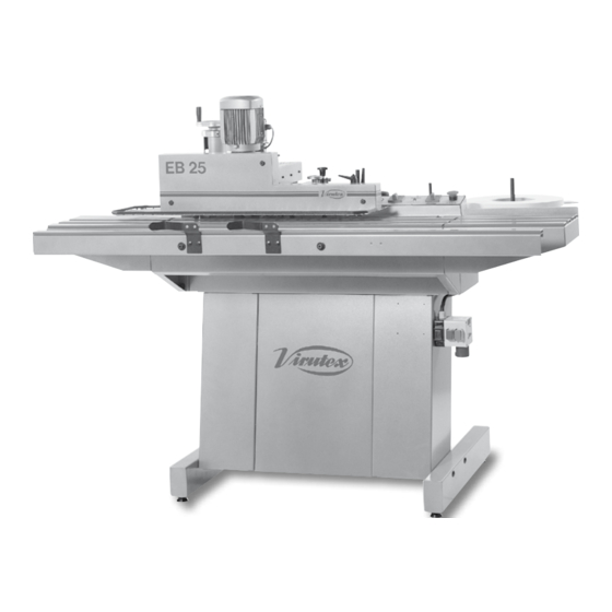
    Pour toute réparation, s'adresser au Service Officiel d'Assistance Technique VIRUTEX. 4. ABMESSUNGEN DER KANTENANLEIMMASCHINE VIRUTEX se réserve le droit de modifier ses produits sans Auf (Abb. 1) sieht man den Raum, den die Kantenanleim- avis préalable. maschine einnimmt.
  • Seite 15: Temperaturregelung

    mit den Schrauben U1. das Band mit der Hand bis zur Messerschneide und legen Sie - Setzen Sie die Bandladevorrichtung B ein, und überprüfen dann ein Brett auf den Tisch. Stützen Sie das Brett auf der Sie, daß sie sich frei drehen kann. Vorderseite des Steuerkastens U (Abb.
  • Seite 16 Position an. Wenn Sie beim Auswechseln der Bürsten abgesprungene Stellen oder Beschädigungen amLäuferschleifring festste- llen, raten wir Ihnen, ihn beim VIRUTEX-Kundendienst auf 11. REGULIERUNG DER TRIMMERMESSER der Drehbank nacharbeiten zu lassen, ehe Sie neue Bürsten Heben Sie mit dem Knauf M den oberen Messerhalter an, einsetzen.
  • Seite 17: Dotazione Standard

    4. Gruppo lato sinistro 19. GARANTIE 5. Scatola contenente: - Caricatore nastro Alle maschinen von VIRUTEX haben eine Garantie von 12 - Supporto caricatore Monaten ab dem Lieferdatum. Hiervon ausgeschlossen sind - Gruppo di pressione alle Eingriffe oder Schäden aufgrund von unsachgemäßem - Prolunga elettrica Gebrauch oder natürlicher Abnutzung des Geräts.
  • Seite 18: Regolazione Della Temperatura

    Ciascun lato è dotato di quattro viti M6 x 15 e di due spine occorrerà premere previamente il termointerruttore N1 e di riferimento; per procedere al montaggio, realizzare le ripetere le operazioni procedenti. seguenti operazioni (Fig. 2): L'arresto di emergenza è stato progettato in modo tale che, - Estrarre le quattro viti A dal banco e sistemare corretta- se viene azionato, tutte le funzioni della macchina vengano mente il lato P1 rispetto al lato del banco mediante le due...
  • Seite 19: Regolazione Guida Allungabile

    Sollevare le molle C1 (Fig. 16 bis) che premono sulle spazzole fissano i coltelli (Fig. 15). Togliere i coltelli. e sostituirle con nuove spazzole originali VIRUTEX, contro- I coltelli tagliano da entrambi i lati del dente (filo 1 e filo 2), llando che scorrano senza difficoltà...
  • Seite 20: Garanzia

    La VIRUTEX si riserva il diritto di modificare i propri prodotti 16. SOSTITUZIONE DELLA senza preavviso. CINGHIA DI TRASCINAMENTO Estrarre le tre viti J1 (Fig. 11) e togliere il coperchio. Allentare la puleggia di tensione K1, mollando la cinghia P O R T U G U É S se necessario, (Fig.
  • Seite 21: Regulação Da Temperatura

    O espaço ocupado pela Orladora, encontra-se representado motor alimentador D, de um indicador luminoso E do estado na (Fig. 1). da máquina (parada ou em funcionamento) e de um botao regulador G para adaptar a temperatura do aquecedor. A manobra para a entrada em funcionamento da máquina 5.
  • Seite 22 Retirar igualmente os parafusos A1 que sujeitam as na- Levantar as molas C1 (Fig. 16 bis) que exercem pressão nas valhas, (Fig. 15). escovas e substituir estas por outras originais VIRUTEX, Retirar as navalhas. assegurando-se de que elas deslizem suavemente pelo As navalhas têm gume pelos dois lados do dente (cortes 1...
  • Seite 23 Tirar os três parafusos J1, (Fig. 11), e retirar também a tampa. Afrouxar a polia tensora K1, destensando, se fosse A VIRUTEX reserva para si o direito de poder modificar os necessário, a correia, (Fig. 18). seus produtos, sem a necessidade de aviso prévio.
  • Seite 24 Accès à toute l’information technique. Zugang zu allen technischen Daten. Accedere a tutte le informazioni tecniche. Aceso a todas as informações técnicas. Dostęp do wszystkich informacji technicznych. Доступ ко всей технической информации. 6396058 042013 Virutex, S.A. Antoni Capmany, 1 08028 Barcelona (Spain) www.virutex.es...

Inhaltsverzeichnis