Werbung
Verfügbare Sprachen
Verfügbare Sprachen
Quicklinks
E N GLI SH
INSTALLATION AND MAINTENANCE INSTRUCTIONS
TC809EA1035 Monitor Module
SPECIFICATIONS
Communications Loop
Nominal Operating Voltage:
Average Operating Current:
Maximum Alarm Current
Monitoring Line
EOL Resistance:
Maximum Wiring Resistance:
Maximum Voltage to EOL:
Maximum Short Circuit Current:
BEFORE INSTALLING
This information is included as a quick reference installation guide. Refer
to the control panel installation manual for detailed system information.
If the modules will be installed in an existing operational system, inform
the operator and local authority that the system will be temporarily out
of service. Disconnect power to the control panel before installing the
modules.
NOTICE: This manual should be left with the owner/user of this
equipment.
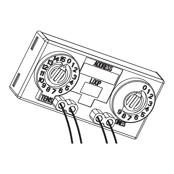
GENERAL DESCRIPTION
The TC809EA1035 monitor module can be installed in a single gang
junction box directly behind the monitored unit. Its small size and light
weight allow it to be installed without rigid mounting (see Figure 1). The
TC809EA1035 is intended for use in intelligent, two-wire systems where
the individual address of each module is selected using rotary decade
switches. It provides a two-wire initiating circuit for normally open
contact fire alarm and security devices.
COMPATIBILITY REQUIREMENTS
To ensure proper operation, this module should only be connected to a
compatible control panel.
FIGURE 1:
HW-460-019
15-32 VDC
400 µA, 1 comm. every 5 seconds,
(Standard 47K EOL)
600 µA
47K Ohms Standard
1.5K Ohms
11 Volts
217 µA
C01063-00
General
Temperature Range:
Humidity:
Dimensions:
Wire Length:
MOUNTING AND WIRING
NOTE: This module is intended to be wired and mounted without rigid
connections inside a standard electrical box. All wiring must conform to
applicable local codes and regulations.
1.
Connect the red (+) and black ( – ) wires to the positive and negative
leads of the communication loop.
2.
Connect the violet (+) and yellow ( – ) wires to a two-wire, normally
open monitoring line.
3.
Install the specified EOL resistor value to terminate the monitoring
line. The EOL resistor for standard use is 47K Ohms – the other
resistors are for special use only.
4.
Set the address on the module per job drawings.
5.
Install the module in the desired mounting location.
FIGURE 2. TYPICAL CIRCUIT CONFIGURATION:
COMPATIBLE
FIRE DETECTION AND
CONTROL
ALARM SYSTEM LOOP
PANEL
(+)
(–)
ALL WIRING
SHOWN IS
SUPERVISED AND
POWER LIMITED
MONITORING LINE
0359
13
System Sensor de México S.A. de C.V.
Ave. Valle del Cedro No. 1681, Parque Industrial Intermex
Ciudad Juárez, Chihuahua, CP 32574, Mexico
1
Honeywell Building Solutions
Honeywell House, Arlington Business Park
Bracknell, Berkshire
-10°C to 55°C
10% to 93% Non-condensing
33mm H x 71mm W x 15mm D
150mm minimum
COMMUNICATION LOOP
(–)
(+)
)
( +
)
( –
6 7 8 9
6
7 8
9
5
5
10
4
11
4
3
3
12
13
2
2
1
14
1
0
0
15
VIOLET
YELLOW
EN 54-18: 2005
DOP-IOD005
Input Output Device
TC809EA1035
RG12 1EB, UK
TO
NEXT
DEVICE
EOL
RESISTOR
INCLUDED
(47K OHMS
47k EOL
STANDARD
INCLUDED
- ELR-47K)
(ELR-47k)
C0614-05
I56-3992-004
Werbung

Verwandte Anleitungen für Honeywell TC809EA1035


Inhaltszusammenfassung für Honeywell TC809EA1035
-
Seite 4: Spezifikationen
Dank der kompakten Abmessungen und des geringen Gewichts kann die Installation des Moduls ohne starre Verbindungen erfolgen ABBILDUNG 2 – TYPISCHE SCHALTKREISKONFIGURATION (siehe Abbildung 1). Das TC809EA1035 Modul ist für den Einsatz in intelligenten Zweileitungssystemen vorgesehen, in denen die individuelle KOMPATIBLE BRANDMELDER- Adresse jedes Moduls über Dekaden-Drehschalter gewählt wird.