Werbung
Verfügbare Sprachen
Verfügbare Sprachen
Quicklinks
94 mm
83 mm
1
2
3
4
A B
5
1
6
7
0
8
9
10
8 9
8 9
11
6 7
6 7
10
11
5
5
12
4
4
12
3
3
13
2
2
14
1
1
0
15
0
A
x10
B
x1
C
1:1 M200E-SMB
a
b
-
c
+
-
d
+
e
+
(-) (+)
g
(-)
f
M200E-EOL-C
Fig./Abb. 3
H200-92-01
Honeywell Building Solutions, Honeywell House, Arlington Business Park, Bracknell, Berkshire, RG12 1EB, UK
TC841E1019
23 mm
93
mm
110 g
M200E-SMB
1:3 M200E-PMB
1:2 M200E-DIN
Fig./Abb. 1
TC841E1019
8 9
6 7
10
5
11
4
12
3
13
2
14
1
0
15
A
x10
B
i
(+)
h
Fig./Abb. 2
DOP-IOD036
EN54-17: 2005
EN54-18: 2005
Honeywell Control Systems Ltd
Honeywell House
Arlington Business Park
Bracknell, Berkshire
RG12 1EB, UK
EN
This manual is intended as a quick reference installation guide. Please refer to the
control panel manufacturers installation manual for detailed system information.
60°C
The Honeywell modules are a family of microprocessor controlled interface devices
permitting the monitoring and/or control of auxiliary devices.The TC841E1019
-20°C
provides an interface between a zone of System Sensor manufactured conventional
type fire detection devices and an intelligent signalling loop.
A single tri-colour LED indicates the status of the module. In normal conditions, the
LED can be set by command from the control panel to blink green when the module
is polled. In the case of a fire alarm on the conventional zone, the LED is switched
on constant red by panel command. If a fault is detected on the conventional zone or
the zone supply voltage drops below 18V, or a fault with the external power supply is
signalled, the LED will blink yellow if enabled on the control panel. When a short circuit
is detected on the loop to either side of the module, the LED is switched to show a
145 g
constant yellow light.
SPECIFICATIONS
Intelligent Loop
Operating Voltage Range with Isolator: 15 to 28VDC (Min 17.5VDC for LED operation)
Op. Volt. Range (Isolator Disabled): 15 to 30VDC (Min 17.5VDC for LED operation)
Max. Standby Current (µA @24 V and 25
No Communication:
Communication LED blink enabled - 5 secs:
Read 16 sec. LED blink 8 sec:
Max. Standby Current (mA @24 V and 25
Capacitive EOL only, Loop Powered Conventional Zone:
No Communication:
Communication LED blink enabled - 5 secs:
Read 16 sec. LED blink 8 sec:
LED Current (Red):
LED Current (Yellow):
Maximum rated continuous current with the
Maximum rated isolator switching current (under short circuit) (I
Maximum leakage current (I
Maximum series impedance with the isolator closed (Z
Conventional Zone
Supply Voltage:
Maximum Standby Load Current: 3mA for detectors
Maximum Zone Load:
Maximum Conventional Line Resistance: 50 Ohms (both legs)
8 9
End of Line Capacitor:
6 7
5
4
General
3
2
1
0
Humidity:
x1
C
Ingress protection:
Maximum Wire Gauge:
INSTALLATION
Note: These modules must only be connected to control panels using compatible
proprietary analogue addressable communication protocols for monitoring and control.
Honeywell modules can be mounted in several ways (See Figure 1):
1:1 An M200E-SMB custom low profile surface-mounting box. The SMB Base is
affixed to mounting surface, and then the module and cover are screwed onto
the base using the two screws supplied. Box dimensions: 132mm(H) x 137mm(W)
x 40mm(D)
1:2 An M200E-DIN Adaptor allows mounting onto standard 35mm x 7.5mm "Top Hat"
DIN rail inside a control panel or other suitable enclosure. Push module into adaptor
bracket until it clips into place. Locate top clip over DIN rail and rotate bottom down
to clip into place. To remove, lift up, then rotate top away from the rail.
1:3 An M200E-PMB Panel Mount Bracket allows the module to be mounted directly
into a panel or other suitable enclosure. Adaptor bracket is mounted directly into
panel using 2 x M4 Pan head screws. Module is pushed into adaptor until it clips
into place.
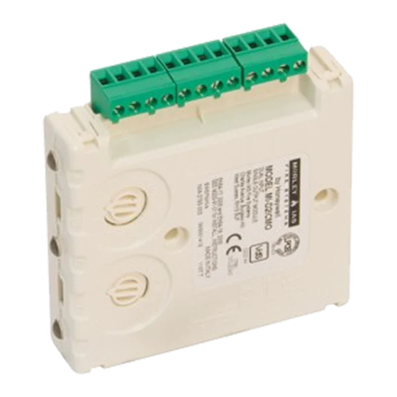
Wiring to all Honeywell modules is via plug in type terminals capable of supporting
conductors up to 2.5mm²
Disconnect loop power before installing modules or sensors.
The module address is selected by means of rotary decade address switches (see
2831
Figure 3). A screwdriver should be used to rotate the wheels to select the desired
08
address, either from the front or the top of the module.
Note: The number of addresses available will be dependent on panel capability,
check the panel documentation for information on this.
Short Circuit Isolators
All Honeywell modules are provided with short circuit monitoring and isolators on the
intelligent loop. If required the isolators may be wired out of the loop to facilitate the
use of the modules on high current loaded loops, for example if sounders are used.
To achieve this, the loop out positive should be wired to terminal 5 rather than terminal
2. See Figure 2 for details.
INSTALLATION INSTRUCTIONS - TC841E1019
CONVENTIONAL ZONE INTERFACE MODULE
18 to 32VDC if conventional zone is loop powered
18 to 32VDC if conventional zone is loop powered
C) External Supply Conventional Zone:
o
C) Conventional Zone connected to
o
2.2mA
8.8mA
isolator
max) with the isolator open (isolated state): 15mA
L
18 to 32 VDC (either from loop or external supply)
15mA (Limited internally)
47μF non-polarised. M200E-EOL-C supplied
5% to 95% relative humidity (non-condensing)
IP50 (Mounted in M200E-SMB)
2.5mm²
CAUTION
I 56- 2127- 021
288
500
388
1.3
1.5
1.6
closed (I
max): 1A
c
max): 1A
s
max): 170 m ohm at 15Vdc
c
I56-2127-021
Werbung

Verwandte Anleitungen für Honeywell TC841E1019


Inhaltszusammenfassung für Honeywell TC841E1019
- Seite 1 2 x M4 Pan head screws. Module is pushed into adaptor until it clips Fig./Abb. 2 into place. M200E-EOL-C Wiring to all Honeywell modules is via plug in type terminals capable of supporting conductors up to 2.5mm² CAUTION Disconnect loop power before installing modules or sensors.
- Seite 2 Protezione ingressi: IP50 (montato su M200E-SMB) TC841E1019 Wiring Massimo calibro del filo: 2.5mm² The TC841E1019 can be wired so as to power the conventional zone either from INSTALLAZIONE an external supply, or directly from the communications loop provided it can supply Nota: Questi moduli possono essere collegati esclusivamente a pannelli di controllo sufficient current.
- Seite 3 Conexiones TC841E1019 Un único LED tricolor indica el estado del módulo. En condiciones normales, el El TC841E1019 se puede conectar para que la zona convencional se alimente LED se puede ajustar desde la central de incendios para que parpadee en verde externamente o directamente del lazo de comunicaciones si éste puede suministrar...
- Seite 4 (siehe Abbildung 3). Dieser kann von der vorne oder der rechten Seite des Moduls erreicht werden. Anmerkung: Einige Brandmelderzentralen können nur 99 Adressen benutzten. H200-92-01 Honeywell Building Solutions, Honeywell House, Arlington Business Park, Bracknell, Berkshire, RG12 1EB, UK I56-2127-021...