
Verwandte Anleitungen für SCS PTC-IIIusb


Inhaltszusammenfassung für SCS PTC-IIIusb
- Seite 1 PTC-IIIusb Installationsanleitung Installation Guide Deutsch / English c Copyright 2003 – 2012 SCS GmbH & Co. KG...
- Seite 3 fitness for any particular purpose. Further, SCS reserves the right to revise this publication, hardware, and software, and to make changes from time to time in the content thereof without the obligation of SCS to notify any persons of such revisions or changes.
- Seite 4 Special Communications Systems Federal Communications Commission (FCC) Statement This equipment has been tested by a FCC accredited testing facility and found to comply with the limits for Class B Digital Device, persuant to Part 15 of the FCC rules. These rules are designed to provide reasonable protection against harmful interference in a residential installation.
- Seite 5 Deutsch Seite 1 English Page 27...
- Seite 7 Software auf der beiliegenden SCS CD-ROM. 1.6 Die SCS CD-ROM Auf der beiliegenden CD finden Sie die Software und Tools, die Sie für den Betrieb des PTC-IIIusb be- nötigen und weitere wertvolle Tipps und Informationen rund um den PTC-IIIusb. Außerdem befindet...
- Seite 8 - Nicht möglich mit diesem Programm. Tabelle 1: Programm Übersicht Immer wieder werden wir gefragt: „Was ist das beste Programm für den PTC-IIIusb?“. Diese Frage können wir eigentlich nicht beantworten, denn es ist ungefähr genauso, als würden Sie fragen „Was ist das beste Auto?“...
-
Seite 9: Die Scs Cd-Rom
Keines der Programme (ausgenommen SCSupdate, SCSmail und EasyTransfer) wurde von SCS entwickelt! Bei Problemen wenden Sie sich bitte an den jeweiligen Autor! Die SCS CD-ROM wird in der Regel zweimal im Jahr neu aufgelegt. Prüfen Sie trotzdem ob nicht neuere Programmversionen im Internet zur Verfügung stehen! - Seite 10 • CCIR 491-Nummern-Selcals (4- und 5-stellig), sowie WRU-Erkennung und Answerback für kom- fortablen Zugriff auf SITOR-Küstenfunkstellen. Für den dauerhaften Betrieb der Professional-Firmware benötigen Sie eine Lizenz (im PTC-IIIusb schon enthalten!). Preise sowie ein ausführliches Handbuch der Professional-Firmware, finden Sie auf der SCS-Homepage im Internet.
-
Seite 11: Die Pactor-Ip-Bridge
"Overhead" der Protokolle TCP/IP und PPP, die für breitbandige Datenleitungen ausgelegt sind, schrumpft auf das absolut nötige Minimum zusammen. Durch die lokale Abwicklung des PPP- Protokolles zwischen dem PC und dem PTC-IIIusb ergibt sich ein weiterer entscheidender Vorteil: PPP war bisher aufgrund der sehr kurzen "Timeouts" kaum über langsame Kommunikationsstrecken mit relativ großen Verzögerungen einsetzbar - diese "Timeout"-Problematik entfällt gänzlich durch... - Seite 12 Starten Sie SCSupdate und folgen Sie den Anweisungen von oben beginnend nach unten. Als erstes stellen Sie den COM-Port ein, mit welchem der PTC-IIIusb verbunden ist. SCSupdate findet das Mo- dem an dieser Schnittstelle und schaltet das Feld "Browse" frei. Hiermit leiten Sie SCSupdate zu dem Verzeichnis, in welchem Sie vorher die dekomprimierte Firmware-Datei (.p3u) abgespeichert haben.
- Seite 13 Sollten Sie doch einmal ein SCS-Produkt zur Reparatur einschicken müssen, beachten Sie bitte fol- gende Hinweise: • Nehmen Sie grundsätzlich immer Kontakt mit SCS per E-Mail auf bevor Sie ein Modem zur Reparatur einsenden. Sie werden wichtige Sendungsinstruktionen erhalten, die Sie befolgen müssen, damit sichergestellt werden kann, dass ihr Gerät gut bei uns ankommt.
- Seite 14 3.2 USB Der PTC-IIIusb ist ein USB 1.1 Device, kann aber problemlos auch an USB 2.0 Schnittstellen betrie- ben werden. Der Anschluss erfolgt über das mitgelieferte Kabel. Für den Betrieb des PTC-IIIusb muß ein passender USB-Treiber installiert werden. Dieser Treiber befindet sich auf der mitgelieferten SCS CD-ROM.
- Seite 15 Der PTC-IIIusb kann zusätzlich mit Bluetooth ausgerüstet werden. Bluetooth dient der Überbrückung kleiner Distanzen mittels einer hochfrequenten (2.4 GHz) Funkstrecke sehr kleiner Leistung und kann damit als Ersatz für eine Kabelverbindung dienen. In Fall des PTC-IIIusb kann damit die in ei- ner Kurzwellen-Umgebung störungsanfällige USB-Kabelverbindung zwischen Modem und PC durch Bluetooth ersetzt werden.
- Seite 16 Sie die "Paarung" gestartet haben, werden Sie nach einem "Schlüssel" oder Passwort gefragt. Hierzu dienen die letzten 8 Ziffern der Seriennummer des PTC-IIIusb. Sie finden die Seriennummer auf der Geräteunterseite. Tippen Sie die letzten 8 Zeichen der Seriennummer (Zahlen oder Buchstaben) als Schlüssel bzw.
- Seite 17 Diese Schalter haben zur Zeit keine Funktion und dienen für spätere Erweiterungen. 3.5 Funkgeräte-Anschluss Aufgrund der Vielfalt der Funkgeräte ist der Anschluss des PTC-IIIusb an das Funkgerät unter Um- ständen etwas komplizierter. Doch keine Panik! Für viele gängige Funkgeräte gibt es fertige Kabel in unserem Zubehörsortiment (siehe Abschnitt...
- Seite 18 Über diesen Eingang können Sie Ihren PTC-IIIusb mit Strom versorgen. Dies ist besonders praktisch, falls das Funkgerät an seiner AUX-Buchse auch die Betriebsspannung bereitstellt. Der PTC-IIIusb benötigt ca. 10 bis 20 V Gleichspannung bei max. 500 mA, typ. 200 mA. Pin 6: Nicht belegt...
- Seite 19 3.5. Funkgeräte-Anschluss Pin Farbe Pin Farbe Lila (violet) Blau (blue) Weiß (white) Rot (red) Gelb (yellow) Schwarz (black) Grün (green) Braun (brown) Tabelle 2: Kabelfarben: 8-pol DIN-Kabel Die 8-polige DIN-Buchse ist wie folgt belegt (Ansicht von hinten auf den PTC): Pin 1: Audio-Ausgang vom PTC zum Funkgerät Pin 2: Masse (GND) Pin 3: PTT-Ausgang...
- Seite 20 3. Installation 3.5.1 Verbindung PTC – ICOM Die folgende Anschlussbelegung passt eigentlich bei fast allen ICOM-Geräten die über eine 8-polige DIN-Buchse (ACC) verfügen: Signal Farbe ICOM 8-pol Pin 2 Weiß Pin 2 Pin 3 Gelb Pin 3 NF-OUT Pin 1 Lila Pin 4 NF-IN Pin 4 Grün...
- Seite 21 3.5. Funkgeräte-Anschluss 3.5.2 Verbindung PTC – KENWOOD Fast alle KENWOOD-Geräte können über die 13-polige ACC2-Buchse angeschlossen werden: Signal Farbe KENWOOD Pin 2 Weiß Pin 4,8,12 Pin 3 Gelb Pin 9 NF-OUT Pin 1 Lila Pin 11 NF-IN Pin 4 Grün Pin 3 Auch als fertiges Kabel erhältlich! Siehe Abschnitt...
- Seite 22 Tabelle 11: YAESU 6-pol Mini-DIN 3.5.4 Einstellen der Amplituden Die Ausgangsamplitude des PTC-IIIusb muß sehr sorgfältig auf das verwendete Funkgerät angepaßt werden. Wird hier die nötige Sorgfalt nicht beachtet, so führt dies zu einem unnötig breitem Signal! Die Ausgangsamplituden werden für die FSK-Betriebsarten (PACTOR-I, AMTOR, RTTY usw.) und für die PSK-Betriebsarten (PACTOR-II / PACTOR-III) getrennt eingestellt.
- Seite 23 TRX mit 100 W maximaler Ausgangsleistung handelt. 3.6 Transceiver Steuerung Der SCS PTC-IIIusb ist mit einem Anschluss zur Steuerung vieler gängiger Transceiver ausgestattet. Über eine Fernsteuermöglichkeit verfügen heute fast alle modernen Funkgeräte der Hersteller KEN- WOOD, ICOM, YAESU, SGC und R&S. Über den Fernsteuereingang lassen sich, je nach Typ und Hersteller, fast alle Funkgeräteparameter abfragen und natürlich auch verändern.
- Seite 24 Die neuere Gerätegeneration (ab TS-570) besitzt am Gerät einen D-Sub-Stecker und arbeitet mit V24- Pegel. Sie ist zum direkten Anschluss an die serielle Schnittstelle eines PC gedacht. Auch diese Geräte kann der PTC-IIIusb problemlos ansteuern. Löten Sie einfach eine 9-polige D-Sub- Buchse nach folgendem Schema an das mitgelieferte Kabel.
- Seite 25 3.6. Transceiver Steuerung Signal PTC Farbe KENWOOD Pin 3 Gelb Pin 3 Pin 8 Pin 2 Pin 4 Grün Pin 8 Pin 2 Weiß Pin 7 Pin 13 Orange Pin 5 Auch als fertiges Kabel erhältlich! Siehe Abschnitt auf Seite Tabelle 14: KENWOOD V24 3.6.2 Verbindung PTC –...
- Seite 26 Die neuere Gerätegeneration (z. B. FT-920, FT-847, FT-1000MP) besitzt am Gerät eine D-Sub-Buchse und arbeitet mit V24-Pegel. Sie ist zum direkten Anschluss an die serielle Schnittstelle eines PC gedacht. Auch diese Geräte kann der PTC-IIIusb problemlos ansteuern. Löten Sie einfach einen 9-poligen D-Sub-Stecker nach folgendem Schema an das mitgelieferte Kabel. Signal PTC...
- Seite 27 3.7. GPS 3.7 GPS Der PTC-IIIusb besitzt eine dreipolige Schraubklemme zum Anschluss des GPS-Empfängers. Der Eingang verkraftet sowohl TLL- als auch RS232-Pegel. Die Anschlussbelegung ist wie folgt: Shield Abbildung 6: GPS Anschluss...
-
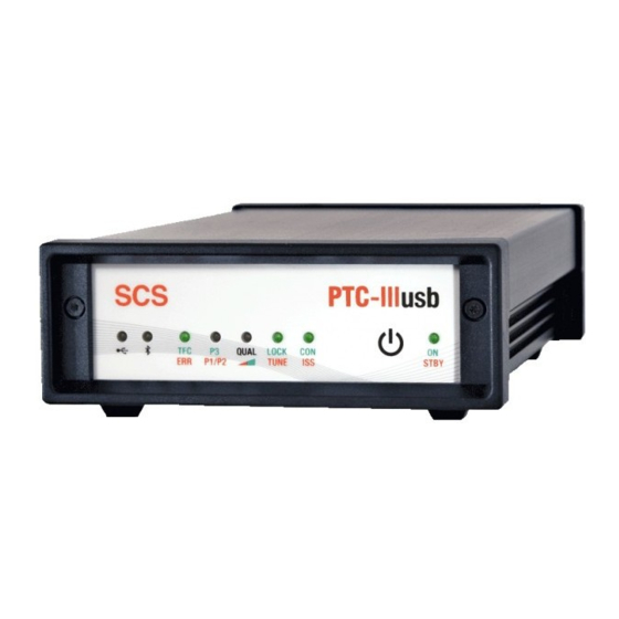
Seite 28: Die Leuchtdioden
USB-LED: Die USB-LED zeigt Aktivität auf der USB-Schnittstelle. Die LED leuchtet rot für Daten die der PTC- IIIusb an den PC sendet und grün für Daten der PC an den PTC-IIIusb sendet. Bluetooth-LED: Die LED leuchtet blau bei Datenverkehr über Bluetooth. - Seite 29 "die Tasten hat". ON /STBY: Die LED leuchtet grün (ON) wenn der PTC-IIIusb eingeschaltet ist. Sie leuchtet rot (STBY) wenn sich der PTC-IIIusb im Stand-By-Zustand befindet, d.h. der PTC-IIIusb ist ausgeschaltet, wird aber immer noch mit Strom versorgt. Im Stand-By-Zustand kann der PTC-IIIusb durch eine kurze Berührung des Sensor-Schalters eingeschaltet werden.
- Seite 30 5. Zubehör 5 Zubehör Für die SCS PTC Serie ist folgendes Zubehör erhältlich: • ICOM 8-pol Kabel ICOM Audio Kabel, PTC 8-pol DIN auf ICOM 8-pol DIN (z. B. für M-710, IC-735, IC-765, IC-802, usw.). Bestell-Nr.: 8090 • ICOM 13-pol Kabel ICOM Audio Kabel, PTC 8-pol DIN auf ICOM 13-pol DIN (z.
- Seite 31 5. Zubehör gesteckt. Bestell-Nr.: 2370 Abgeschirmte Verbindungskabel mit angespritztem Stecker und flexibler Zugentlastung. Das andere Kabelende ist offen. Jede Ader ist abisoliert und verzinnt. Kabellänge ca. 1,5 Meter. • Kabel mit 5-pol DIN Stecker Bestell-Nr.: 8010 • Kabel mit 8-pol DIN Stecker Bestell-Nr.: 8020 •...
-
Seite 32: Technische Daten
6. Technische Daten 6 Technische Daten NF-Eingangsimpedanz: 47 k NF-Eingangspegel: 10 mV – 2 V NF-Ausgangsimpedanz: NF-Ausgangspegel: max. 3 V (Leerlauf) einstellbar in 1 mV Schritten NF-Verarbeitung: Digitaler Signalprozessor DSP56303 mit 100 MHz 768 kByte zusätzliches DSP-RAM für Daten und Programm Prozessor: Motorola MC68360 QUICC 32 Bit CMOS CPU getaktet mit 25 MHz... -
Seite 33: Packaging List
PC. Your service provider typically distributes the email client software. The client software performs most of the configurations and modem settings to get you on the air. You will find many popular software packages on the SCS CD-ROM supplied with your PTC. - Seite 34 Windows programs usually need Windows 98 or higher. EasyTransfer, SCSmail, and SCSupdate are the only programs that have been developed by SCS. The SCS CD-ROM is usually updated twice the year. Always check if there is a newer version of your selected program available from the Internet.
- Seite 35 Not possible with this software. Professional solutions SCS has developed a Professional version of the firmware which enables new modes for the PTC. The “Professional Firmware” meets many special requirements for mobile and maritime users and services. It also provides the high-speed PACTOR-III mode.
- Seite 36 Fully backwards compatible to existing PACTOR-I/II networks. 1.7.2 PACTOR-IP-Bridge The PACTOR-IP-Bridge (PIB) is a new Network-Integration-Protocol developed by SCS. The dominant protocols of the Internet like TCP/IP, as well as the Point-to-Point Protocol (PPP), which have become standard for establishment of links between Internet applications, are combined with the PACTOR modes.
- Seite 37 Usually it will be a compressed file (-zip) which you need to unzip before you use it. Unzip and store the file in a certain folder, for the PTC-IIIusb, the firmware file will have the ending “.p3u”.
- Seite 38 SCS-Update server. If available, beta firmware versions will also be offered in addition. Of course it is still possible for locally saved firmware data to be installed on your SCS modem using SCSupdate 2.0 as before. The program is dialog based and guides you step by step through the update procedure for your SCS modem.
- Seite 39 PACTOR and the PTC automatically by email. Repairs If a problem occurs and it’s necessary to send your SCS product to maintenance, please take care of the following: Always contact SCS by email before sending a modem. You will be supplied with return instructions which are important for receiving modems from outside the EU.
-
Seite 40: Installation
The inputs are also protected by a self-resetting fuse. The PTC-IIIusb is a USB 1.1 device and can be operated in an USB 2.0 environment as well. The connection to the computer is done with the attached USB cable. - Seite 41 Bluetooth Sticks of various brands are available from computer stores. The installation should be done in accordance with the instructions of the Bluetooth Stick vendor (driver and software, etc.). SCS does not supply Bluetooth stick software on the SCS-CD. Please use the CD from the Bluetooth Stick manufacturer for the installation! After installation (or after the first connection with the PTC modem), a virtual COM port is generated (just like with USB) which can be accessed by any terminal or PTC program.
- Seite 42 Now you need to “pair” the PTC-IIIusb with the PC, so that both will recognize each other next time. Usually the manager offers you the pairing option when you double-click on the symbol, or by right clicking the symbol.
- Seite 43 To archive this, the rear dip switch #1 (labeled with ON) must be set. In this condition the PTC-IIIusb is always on when it has supply power. It cannot be switched off any more with the sensor. The modem can only be switched off by cutting the external power supply.
- Seite 44 3. Installation modulator to generate the HF signal. This is of no disadvantage, providing the transceiver is not overdriven. Some useful hints to properly setup the transceiver: If possible use a 500 Hz IF-filter for PACTOR-II. Never use a IF-filter with a smaller bandwidth than 500 Hz! IF filters (SSB-filters) with wider bandwidths won´t cause problems at all.
- Seite 45 3. Installation If you do not find a matching cable there, then use the attached 8 pin DIN cable and complete it to connect the PTC to the transceiver: Color Color Violet Blue White Yellow Black Green Brown Table 2: Cable Colors: 8 pin DIN cable The socket is wired as follows (seen from the rear of the PTC).
- Seite 46 3. Installation 3.5.1 Connection PTC – ICOM Most ICOM transceivers that use 8 pin DIN plug (ACC) can be connected this way: Signal Color ICOM 8 pin PIN 2 white PIN 2 PIN 3 yellow PIN 3 AF-OUT PIN 1 violet PIN 4 AF-IN...
- Seite 47 3. Installation 3.5.2 Connection PTC – Kenwood Most Kenwood transceivers that use 13 pin DIN plug (ACC2) can be connected this way: Signal Color Kenwood PIN 2 white PIN 4, 8, 12 PIN 3 yellow PIN 9 AF-OUT PIN 1 violet PIN 11 AF-IN...
- Seite 48 3. Installation - For HF and 1k2 Packet-Radio: Signal Color YAESU PIN 2 white PIN 2 PIN 3 yellow PIN 3 AF-OUT PIN 1 violet PIN 1 AF-IN PIN 4 green PIN 5 This cable is available completely assembled. Refer to chapter on page 49.
- Seite 49 With radio equipment that is digitally controlled, the list of functions is almost unlimited. The PTC-IIIusb uses this features mainly to set and readout the frequency of the transceiver. You find more about the transceiver remote control in chapter TRX in the main manual.
- Seite 50 3. Installation TxD V24 Transmit data from the PTC to the transceiver. V24 level! RxD V24 Receive data from the transceiver to the PTC. V24 level! CTS V24 Handshake signal from the transceiver to the PTC. V24 level! RTS V24 Handshake signal from the PTC to the transceiver.
- Seite 51 V24 levels for transceiver control. It´s intended for direct connection to a COM port of a PC. Also these transceivers can easily be controlled by the PTC-IIIusb. Just solder a 9 pin connector to the attached cable as shown in the table below.
- Seite 52 Newer YAESU’s (FT-920, FT-847, FT-1000MP) use a 9 pin SUB-D connector and V24 levels for control, intended for connection to a COM port of a PC. Also these radios can be controlled by the PTC-IIIusb. Solder a 9 pin connector to the attached cable as shown in the table 16. Signal...
- Seite 53 4 LED's Figure 8: The PTC-IIIusb front The SCS PTC-IIIusb is equipped with 7 dual-colour LED´s to display the most essential status information and a blue single-colour LED to show Bluetooth activity. The meaning of the LED´s is explained as follows. Described from left to right.
- Seite 54 4. LED’s Lock/Tune: In unconnected/STBY state (e. g. while receiving RTTY, PACTOR Unproto, etc.): Forms a 2-LED tuning indicator together with the QUAL LED. Bright green indicates best tuning of the RX signal, very dim red or un-lit LED indicates poorest frequency tuning of the RX signal.
- Seite 55 5 Accessories 5 Accessories For the SCS PTC series the following accessories are available: ICOM 8 pin cable ICOM audio cable, PTC 8 pin DIN to ICOM 8 pin DIN (e.g. for M710, IC-735, IC765, IC-M802 and more). Order-No.: 8090 ICOM 13 pin cable ICOM audio cable, PTC 8 pin DIN to ICOM 13 pin DIN (e.g.
- Seite 56 Cable with 5 pin DIN connector Order-No.: 8010 Cable with 8 pin DIN connector Order-No.: 8020 Cable with 13 pin DIN connector Order-No.: 8070 For additional accessories and prices please refer to our homepage http://www.scs-ptc.com call for a recent pricelist.
-
Seite 57: Technical Data
6 Technical Data 6 Technical Data Audio input impedance: 47 k Audio input level: 10 mVp-p... 2Vp-p Audio output impedance: Audio output level: Max. 3 Vp-p (open circuit), adjustable in 1 mV steps Audio processing: Digital signal processor DSP56303 clocked at 100 MHz 768 kByte additional DSP-RAM for data and program Central processor: Motorola MC68360 QUICC 32 bit CMOS CPU clocked at 25 MHz...