Telos Alliance xNode Serie Bedienungsanleitung
Inhaltsverzeichnis
Quicklinks
Inhaltsverzeichnis

Inhaltszusammenfassung für Telos Alliance xNode Serie
- Seite 1 xNode Installation & User’s Guide Manual Rev 2.0.1 - February 2017 p/n 1490-00081-004...
- Seite 2 If the equipment is used in a manner not specified by the manufacturer, the protection provided by the equipment may be impaired. © 2017 Telos Alliance - Rev 2.0.1...
- Seite 3 Gerät nicht auf einem Teppich, Poster oder andere Materialien welche die Lüftungsöffnungen beeinträchtigen könnten. Wird das Gerät anders als in der, vom Hersteller angegebenen Weise verwendet, kann der, durch das Gerät gegebene Schutz beeinträchtigt werden. © 2017 Telos Alliance - Rev 2.0.1...
- Seite 4 This device complies with the requirements of the EEC council directives: • 93/68/EEC (CE MARKING) • 73/23/EEC (SAFETY – LOW VOLTAGE DIRECTIVE) • 89/336/EEC (ELECTROMAGNETIC COMPATIBILITY) Conformity is declared to those standards: EN50081-1, EN50082-1. © 2017 Telos Alliance - Rev 2.0.1...
- Seite 5 The operation of Fusion is determined largely by software. We routinely release new versions to add features and fix bugs. Check the Telos Alliance web site for the latest. We encourage you to sign-up for the email notification service offered on the site.
- Seite 6 • All other questions, please email inquiry@telosalliance.com. VIA WORLD WIDE WEB: The Telos Alliance web site has a variety of information which may be useful for product selection and support. The url is telosalliance.com. REGISTER YOUR PRODUCT Did you know that all Telos Alliance products come with a 5-Year Warranty? Take a moment to activate your coverage online at telosalliance.com/product-registration/...
-
Seite 7: Inhaltsverzeichnis
Chapter Five: AES xNode . . . . . . . . . . . . . . . . 27 Appendix D: Telos Alliance Limited Warranty . . . . . 55 Rear Panel . - Seite 8 Dear Valued Customer, It’s with great pride and a tip of the hat to an incredible team that I congratulate you on your new Telos Alliance product. Everything we do here at the radio division of the Telos Alliance is with one end goal in mind: To help broadcasters declare victory in extremely competitive environments.
-
Seite 9: Chapter One: Introducing The Xnode
Dual 100BT Ethernet ports, usable as mirroring redundant ports or as a single Livewire port and separate management port. • Thermal sensor monitors temperature and provides notification of over-temp condition. • IEEE 1588 synchronization support • Ravenna stream routing support © 2017 Telos Alliance - Rev 2.0.1... -
Seite 10: The Front Panel
The Front Panel Figure 1-1: xNode Front Panel The xNode uses the OLED display on the left hand side to provide status information and assist with initialsetup. Figure 1-2: xNode OLED Display © 2017 Telos Alliance - Rev 2.0.1... -
Seite 11: Rear Panel
Chapter 4. AES/EBU Four AES-3 inputs and four AES-3 outputs are available in parallel through the RJ45 ports or the DB-25 ports. Pin- out information is available in Chapter 5. © 2017 Telos Alliance - Rev 2.0.1... -
Seite 12: Microphone
192.168.1.15 255.255.255.0 defines the network prefix (subnet) as 192.168.1 and defines the host number as 15. So two devices within the same subnet would have the same prefix, but required to have different host numbers. 192.168.1.15 and 192.168.1.25 for example. © 2017 Telos Alliance - Rev 2.0.1... - Seite 13 (UI). This UI is presented on the screen of iProbe and is the HTML interface as mentioned here. Authentication is the same through iProbe as with a web browser. © 2017 Telos Alliance - Rev 2.0.1...
-
Seite 14: Chapter Two: Configuration
(an IP address of 10.216.0.100 would be suitable) • Open a browser and type in the IP address of the xNode (10.216.0.101) into the URL field. • Default Authentication is: Username: user Password: (there is no password) © 2017 Telos Alliance - Rev 2.0.1... - Seite 15 You’re done! These steps were designed to get you up and running quickly, but if you need more details on other configuration options, please continue to read this chapter. For additional information on a particular xNode, look at the following chapters which are dedicated to each model. © 2017 Telos Alliance - Rev 2.0.1...
-
Seite 16: Assigning An Ip Address Manually
Number ranges of 100-319 (abc) support large networks with up to 2299 nodes. When the 3 digit ID is being used, a second level identifier becomes available with range of d=<0-9>. The node ID determines IP address in range: 10.216.ab.1cd. Channel numbers: abcd1-abcd8. © 2017 Telos Alliance - Rev 2.0.1... -
Seite 17: Iprobe Configuration
The setup page will vary based on what xNode you are configuring. If it is an audio xNode, there will be a section for Sources and a section for Destinations. If GPIO (General Purpose Input/Output) functionality is on the xNode, there will be section for GPIO. © 2017 Telos Alliance - Rev 2.0.1... -
Seite 18: Restoring Defaults
Disconnect all power from the xNode, then press and hold the two front panel buttons. • Apply power to the xNode while continuing to press the buttons. • xNode will show a countdown timer for factory reset. When the timer reaches 0, release the two buttons. © 2017 Telos Alliance - Rev 2.0.1... -
Seite 19: Chapter Three: The Xnode In Depth
The brackets secure to the side of the xNode, towards the front panel. There are four holes which are used for secur- ing metal work to the xNode. Figure 3-1 Secure the bracket to the xNode with included screws in the desired configuration. Figure 3-2 Outward configuration Figure 3-3: Inward configuration © 2017 Telos Alliance - Rev 2.0.1... -
Seite 20: Optional Rack Mount Kit
Optional Rack Mount kit The optional rack mount kit (p/n 2011-00076) provides the ability to secure the xNode into an equipment rack. Figure 3-4: Short rack ear Figure 3-5: Long rack ear Figure 3-6: Spacer © 2017 Telos Alliance - Rev 2.0.1... - Seite 21 The method of mounting two xNodes together will depend on the revision of chassis you have. The easy indicator is to identify the keyholes in revision 2 If no keyholes are present on the right side, when looking from the front, please skip to Revision 1 section. © 2017 Telos Alliance - Rev 2.0.1...
-
Seite 22: Revision 2
Place the second xNode, so that the shoulder screws of the bracket fit into the keyholes. Slide the xNode into place. NOTE: The shoulder screws may require adjustment for better fit. Lock the xNode in place with a screw secured to the back. © 2017 Telos Alliance - Rev 2.0.1... -
Seite 23: Revision 1
Use the four(4) screws provided to secure the two nodes together. Figure 3-9b Replace the lids on the xNodes. Secure the short rack ears to either side of the two xNodes. Figure 3-10 © 2017 Telos Alliance - Rev 2.0.1... -
Seite 24: Home
4x4 or Mono 8x8 options disable the matrix mixer functionality (explained later in this chapter) and configure the device for those modes. The Mix/Custom mode enables the matrix mixer and allows for customization of mono, stereo, and mixing configurations. Figure 3-11 © 2017 Telos Alliance - Rev 2.0.1... -
Seite 25: Web Interface (Advanced Options)
Specify the sync server if using NTP as the synchronization source. This mode of sync is only good for NTP server: Standard streams and used for unique applications. : Define system location for SNMP System location : Define system contact for SNMP System contact © 2017 Telos Alliance - Rev 2.0.1... -
Seite 26: Qos (Audio Xnodes)
PTP grand master but a master to the Livewire network. This permits the xNode to behave as a gateway of sorts for network synchronization between AES67 devices and legacy Livewire devices. NTP slave is for special applications that synchronize from an NTP source. (Live streams are not supported under NTP mode.) © 2017 Telos Alliance - Rev 2.0.1... -
Seite 27: Ptp Characterizations
These options define the tagging of the packet for Live Audio and clock. Don’t Live Audio / Clock Streams: modify these settings unless instructed to do so by Telos Alliance Support. These options define the tagging of the packet for streams that are not the AES67 / Standard Audio Streams: Live Audio streams. -
Seite 28: Meters (Audio Xnodes)
The meter page shows a stereo channel or a mono channel based on the configuration of the xNode and the amount of channels enabled. The meters are represented in dBFS. Below the meters are gain adjustment buttons which allow for 1dB adjustment (Large button) and 0.1dB adjustment (Small button). Figure 3-12 © 2017 Telos Alliance - Rev 2.0.1... -
Seite 29: Mixer (Audio Xnodes)
In the case of an AES/EBU input on port 1 of the AES/EBU xNode turning into the first network stream source of the xNode, the mixer will show the following view (without the arrows, which are added for clarity). Figure 3-14 © 2017 Telos Alliance - Rev 2.0.1... -
Seite 30: Destinations (Audio Xnode)
The historical use of network inputs being turned into physical outputs will still be more common, but it is important to point out this new distinction in order for you to understand the mixer functionality of 2.0. Figure 3-16 © 2017 Telos Alliance - Rev 2.0.1... -
Seite 31: Sources (Audio Xnode)
When the connection is successful, the icons turn green and Stream active / RTSP OK status is displayed. The Setup interface allow you to save six presets, which can be different remote nodes. Selecting a preset is a fast way of changing the link destination. © 2017 Telos Alliance - Rev 2.0.1... - Seite 32 If the triangle is blinking, the port is configured for Unicast, but there is no active connection. • When the triangle is displayed solid on, there is a Unicast Link established to that port. © 2017 Telos Alliance - Rev 2.0.1...
-
Seite 33: Chapter Four: Analog Xnode
The top 4 RJ-45 style ports are line level analog inputs. The bottom 4 RJ-45 style ports are line level analog outputs. The pinout of an RJ-45 port FUNCTION Left Channel Input/Output + Left Channel Input/Output - Right Channel Input/Output + Ground Not Used Right Channel Input/Output - Not Used Not Used © 2017 Telos Alliance - Rev 2.0.1... - Seite 34 Channel 4a/7 + Channel 4a/7 Gnd Channel 3b/6 - Channel 3a/5 + Channel 3a/5 Gnd Channel 2b/4 - Channel 2a/3 + Channel 2a/3 Gnd Channel 1b/2 - Channel 1a/1 + Channel 1a/1 Gnd © 2017 Telos Alliance - Rev 2.0.1...
-
Seite 35: Chapter Five: Aes Xnode
The top 4 RJ-45 style ports are AES/EBU inputs. The bottom 4 RJ-45 style ports are AES/EBU outputs. The pinout of an RJ-45 port FUNCTION AES Input/Output + AES Input/Output - Not Used Not Used Not Used Not Used Not Used Not Used © 2017 Telos Alliance - Rev 2.0.1... - Seite 36 AES Ch1 - Not Used Not Used Not Used Not Used Not Used Not Used Not Used AES Ch4 - AES Ch3 + AES Ch3 Gnd AES Ch2 - AES Ch1 + AES Ch1 Gnd © 2017 Telos Alliance - Rev 2.0.1...
-
Seite 37: Chapter Six: Microphone Xnode
The top 4 RJ-45 style ports are analog, mono inputs. The bottom 4 RJ-45 style ports are line level analog outputs. The pinout of an RJ-45 port FUNCTION MIC + MIC - Not Used Ground Not Used Not Used Not Used Not Used shld © 2017 Telos Alliance - Rev 2.0.1... - Seite 38 Not Used Not Used MIC Ch4 + MIC Ch4 Gnd Not Used MIC Ch3 + MIC Ch3 Gnd Not Used MIC Ch2 + MIC Ch2 Gnd Not Used MIC Ch1 + MIC Ch1 Gnd © 2017 Telos Alliance - Rev 2.0.1...
- Seite 39 Channel 4a/7 + Channel 4a/7 Gnd Channel 3b/6 - Channel 3a/5 + Channel 3a/5 Gnd Channel 2b/4 - Channel 2a/3 + Channel 2a/3 Gnd Channel 1b/2 - Channel 1a/1 + Channel 1a/1 Gnd © 2017 Telos Alliance - Rev 2.0.1...
-
Seite 40: Chapter Seven: Gpio Xnode
Figure 7-1: GPIO xNode Rear Panel The illustration below shows the connector pinouts; 5 inputs and associated common return, 5 output relays and as- sociated common, a +5 volt power source, and power source ground. Figure 7-2 © 2017 Telos Alliance - Rev 2.0.1... - Seite 41 Figure 7-4 Telos Alliance GPIO accessory modules are designed to interface directly to the GPIO port. The DA-15 connector on the back of an accessory module is a direct pin-to-pin match to the GPIO port of the xNode. Premade cables of this configuration are commonly available through companies that specialize in interconnect cable assembly prod- ucts.
- Seite 42 Figure 7-6 The Telos Alliance accessory modules use the 5vDC supply to illuminate LED based buttons. So a one-to-one pin connection is all that is needed between any accessory modules and a GPIO port. Note that all of the inputs and outputs on a specific GPIO port are “grouped together”. The 5 “Outputs” are on 5 separate output pins, however, they share the same “Common Return”...
-
Seite 43: Simple Setup
– The Pathfinder series of products has the ability to observe GPIO activity as well as Pathfinder control trigger GPO activity. Nothing is required to configure in the GPIO xNode, all the configuration is done in Pathfinder. Please refer to Pathfinder documentation for detailed information. © 2017 Telos Alliance - Rev 2.0.1... -
Seite 44: Other Web Interfaces
GPIO xNode is not an audio device and therefore does not require audio synchronization. System The system page provides access to IP settings, logging options, password change, and software control. The system page is covered in more detail in chapter 3, section Web Interface. © 2017 Telos Alliance - Rev 2.0.1... -
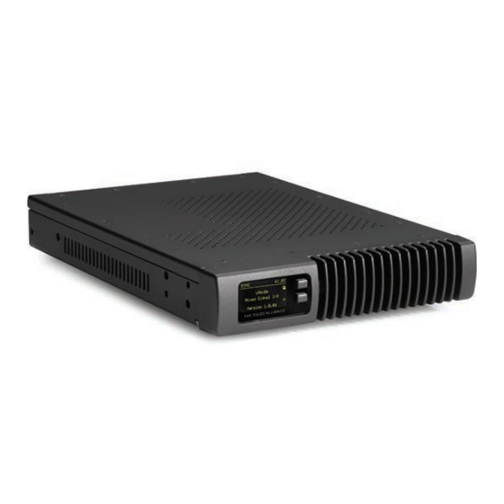
Seite 45: Chapter Eight: Mixed Signal Xnode
Negative The pinout of an RJ-45 port FUNCTION Left Channel /AES Input/Output + Left Channel /AES Input/Output - Right Channel Input/Output + Ground Not Used Right Channel Input/Output - Not Used Not Used © 2017 Telos Alliance - Rev 2.0.1... - Seite 46 INPUT External Series Resistor 680 @ 1/4 watt 1.8k @ 1/2 watt 3.9k @ 1 watt Using external power supplies is the recommended method to avoid possible ground loops between equipment. Figure 8-3 © 2017 Telos Alliance - Rev 2.0.1...
- Seite 47 Figure 8-4 Telos Alliance GPIO accessory modules are designed to interface directly to the GPIO port. The DA-15 connector on the back of an accessory module is a direct pin-to-pin match to the GPIO port of the xNode. Premade cables of this configuration are commonly available through companies that specialize in interconnect cable assembly prod- ucts.
-
Seite 48: Simple Setup
The Telos Alliance accessory modules use the 5vDC supply to illuminate LED based buttons. So a one-to-one pin connection is all that is needed between any accessory modules and a GPIO port. Note, all of the inputs and outputs on a specific GPIO port are “grouped together”. The 5 “Outputs” are on 5 separate output pins, however, they share the same “Common Return”... -
Seite 49: Appendix A: Gpio Logic Table Samples
Input Common Common for all 5 inputs Connect to power supply of source device or to Pin 9 NOT CONNECTED GPIO v.”ZA” 4/2009 © 2017 Telos Alliance - Rev 2.0.1... -
Seite 50: Gpio Control Room Guest Microphone Logic
Source Supply Common for all 5 inputs Connect to power supply of source device or to Pin 9 NOT CONNECTED GPIO v.”ZA” 4/2009 © 2017 Telos Alliance - Rev 2.0.1... -
Seite 51: Gpio Producer's Microphone Logic
Source Supply Common for all 5 inputs Connect to power supply of source device or to Pin 9 NOT CONNECTED GPIO v.”ZA” 4/2009 © 2017 Telos Alliance - Rev 2.0.1... -
Seite 52: Gpio Line Input Logic
Source Supply Common for all 5 inputs Connect to power supply of source device or to Pin 9 NOT CONNECTED GPIO v.”ZA” 4/2009 © 2017 Telos Alliance - Rev 2.0.1... -
Seite 53: Gpio Codec Logic
Source Supply Common for all 5 inputs Connect to power supply of source device or to Pin 9 NOT CONNECTED GPIO v.”ZA” 4/2009 © 2017 Telos Alliance - Rev 2.0.1... -
Seite 54: Gpio Telephone Hybrid Logic
Source Supply Common for all 5 inputs Connect to power supply of source device or to Pin 9 NOT CONNECTED GPIO v.”ZA” 4/2009 © 2017 Telos Alliance - Rev 2.0.1... -
Seite 55: Gpio Control Room Monitor Logic
Source Supply Common for all 5 inputs Connect to power supply of source device or to Pin 9 NOT CONNECTED GPIO v.”ZA” 4/2009 © 2017 Telos Alliance - Rev 2.0.1... -
Seite 56: Gpio Computer Playback Device Logic
Source Supply Common for all 5 inputs Connect to power supply of source device or to Pin 9 NOT CONNECTED GPIO v.”ZA” 4/2009 © 2017 Telos Alliance - Rev 2.0.1... -
Seite 57: Appendix B: Xnode Specifications
• Any input to any output: +/- 0.5 dB, 20 Hz to 20 kHz Latency • Analog Input to Analog Output, 2.75ms including network, converters, and mixing process • Digital Input to Digital Output, 1.75ms including network mixing engine (ASRC off) © 2017 Telos Alliance - Rev 2.0.1... -
Seite 58: Dynamic Range
• 8.5” (22 cm) wide; two may be mounted side-by-side in a standard 1RU rack space (with accessory mounting kit) • 1.72” (4.4 cm) height, 11.75” (30 cm) depth • Shipping Weight: 7 lbs. (3.2 kg.) • Shipping Dimensions: 17” (43.2 cm) length, • 13” (33 cm) width, 7” (17.8 cm) height © 2017 Telos Alliance - Rev 2.0.1... -
Seite 59: Appendix C: Aes67
PTP clock priority1/priority2 numbers provide a control over master clock selection. Lower priority number makes the clock a preferred choice over devices with a higher number. The range is 0 255, and 128 is the default and middle value. © 2017 Telos Alliance - Rev 2.0.1... -
Seite 60: Aes67 Multicast Connection Setup
Surround 8 channel reception is set up by selecting Destination Type: Surround. Channel/Address field accepts optional UDP port number following IP address, separated with a “:”. This is useful option when the port number is different than RTP default 5004. © 2017 Telos Alliance - Rev 2.0.1... -
Seite 61: Aes67 Unicast Setup
Destination to be not configured (empty Channel/Address) field. In order to setup AES67 Unicast stream receive, enter the SIP URI stream address in Channel/Address field of a destination. Figure App-4: Example of unicast receive setup © 2017 Telos Alliance - Rev 2.0.1... - Seite 62 Channel/Address field accepts optional UDP port number in the URI, separated with a “:” from the address part. This is needed when the port number used by sender is different than SIP default 5060. © 2017 Telos Alliance - Rev 2.0.1...
-
Seite 63: Appendix D: Telos Alliance Limited Warranty
Appendix D: Telos Alliance Limited Warranty Telos Alliance Radio Division has an industry-leading five-year warranty. As a company, we are commited to our products and the pursuit of providing better quality to our customers. Find the Warranty online at www.telosalliance.com/warranty. - Seite 64 1241 Superior Ave. • Cleveland, Ohio, 44114, USA • +1.216.241.7225 • TelosAlliance.com © 2017 TLS Corp. The Telos Alliance®. All Rights Reserved. F17/2/16018...