Jacobsen Super LF 1880 Ersatzteile
Mäher fairway mit rops
Inhaltsverzeichnis
Quicklinks
Parts & Maintenance Manual
Ersatzteil- und Wartungshandbuch
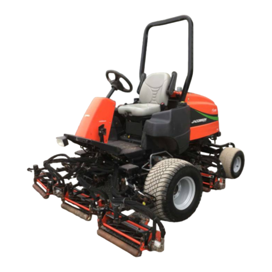
Super LF 1880™ Fairway Mower with ROPS
Super LF 1880™ Mäher Fairway mit ROPS
67955 – Kubota D1105-E3B, 2WD
67956 – Kubota D1105-E3B, 4WD
67957 – Kubota D1105-T-E3B, 4WD
If incorrectly used, this machine can cause severe injury. Those who use
and maintain this machine should be trained in its proper use, warned of its
dangers and should read the entire manual before attempting to set up,
operate, adjust or service the machine
Wenn diese Maschine nicht ordnungsgemäß verwendet wird, können ernsthafte
Verletzungen verursacht werden. Personen, die diese Maschine verwenden und warten,
müssen in ihrer richtigen Verwendung ausgebildet sein, auf die Gefahren aufmerksam
gemacht worden sein und die Anleitung ganz gelesen haben, bevor sie versuchen,
die Maschine aufzustellen, zu bedienen, einzustellen oder zu warten.
DE
GB
German
WARNING
ACHTUNG
4160164-DE
6
5
9
1 1
1 6
1 5
1 3
7
8
1 8
1 7
1 - I N C L U D E S I T E M S 3 - 1 6
1 9
3
1 0
4
When Performance Matters.
™
Kapitel
Inhaltsverzeichnis
Fehlerbehebung

Verwandte Anleitungen für Jacobsen Super LF 1880


Inhaltszusammenfassung für Jacobsen Super LF 1880
- Seite 1 1 - I N C L U D E S I T E M S 3 - 1 6 Parts & Maintenance Manual Ersatzteil- und Wartungshandbuch Super LF 1880™ Fairway Mower with ROPS Super LF 1880™ Mäher Fairway mit ROPS 67955 – Kubota D1105-E3B, 2WD 67956 –...
-
Seite 2: Service Parts
Jacobsen Dealer. Suggested Stocking Guide To Keep your Equipment fully operational and productive, Jacobsen suggests you maintain a stock of the more commonly used maintenance items. We have included part numbers for additional support materials and training aids. To order any of the following material: 3. -
Seite 3: Inhaltsverzeichnis
Table of Contents Safety Maintenance Operating Safety ..........4 General .............. 16 Important Safety Notes .........5 Engine ..............16 Specifications Engine Oil ............16 Product Identification..........6 Air Filter ..............17 Kubota D1105-E Engine ........6 Fuel ..............17 Kubota D1105-TE Engine ........6 Fuel System ............17 Cutting Units: ............7 Battery ..............18 Tractor ..............7... -
Seite 4: Safety
(vertically), not across the face (horizontally). the job. Only use accessories and attachments approved by Jacobsen. 21. To prevent tipping or loss of control, do not start or stop suddenly on slopes. Reduce speed when making sharp Stay alert for holes in the terrain and other hidden turns. -
Seite 5: Important Safety Notes
Adjustments and maintenance should always be performed by a qualified technician. If additional information or service is needed, contact your Authorized Jacobsen Dealer, who is kept informed of the latest methods to service this equipment, and can provide prompt and efficient service. Use of other than original or... -
Seite 6: Specifications
SPECIFICATIONS SPECIFICATIONS PRODUCT IDENTIFICATION _________________________________________________ 67955 ......Super LF 1880 2WD with ROPS 67956 ......Super LF 1880 4WD with ROPS ® 67957 ......Super LF 1880 Turbo 4WD with A Textron Company ROPS CHARLOTTE, NC MADE IN U.S.A. YEAR OF Serial Number .... -
Seite 7: Cutting Units
ACCESSORIES & SUPPORT LITERATURE _____________________________________ Contact your area Jacobsen Dealer for a complete listing of accessories and attachments. CAUTION Use of other than Jacobsen authorized parts and accessories may cause personal injury or damage to the equipment and will void the warranty. Accessories Reels Air Blow Gun ............ -
Seite 8: Adjustments
ADJUSTMENTS ADJUSTMENTS GENERAL________________________________________________________________ adjustment cannot be made, contact an authorized Jacobsen Dealer. WARNING 2. Replace, adjust, worn damaged To prevent injury, lower implements to the ground, components. disengage all drives, engage parking brake, stop 3. Long hair, jewelry or loose fitting clothing may get engine, and remove key from ignition switch before tangled in moving parts. -
Seite 9: Neutral Switch And 4Wd Cut-Out Switch
ADJUSTMENTS NEUTRAL SWITCH AND 4WD CUT-OUT SWITCH________________________________ The traction pedal is designed to return to neutral 2. Adjust switch (I) as required to position the sensing whenever the forward or reverse foot pedals are area under the return arm as shown with pump in released. -
Seite 10: Traction Pedal Speed Limiter
ADJUSTMENTS TRACTION PEDAL SPEED LIMITER __________________________________________ Cutting quality is better at speeds well below the Transport Position Mow Position transport speed of the mower. An initial mow speed of 6 mph is set at the factory and should be satisfactory for most cutting conditions. -
Seite 11: Steering Adjustments
ADJUSTMENTS STEERING ADJUSTMENTS__________________________________________________ Turn wheels to straight ahead position. 2. Loosen jam nuts (Q) on both sides of tie rod (R). 3. Turn tie rod (R) to provide proper toe-in. Toe-in must not exceed +1/16” (1.5 mm) (S). Align ball joints and tighten jam nuts. -
Seite 12: Bedknife-To-Reel
ADJUSTMENTS 3.11 BEDKNIFE-TO-REEL _______________________________________________________ (Pre-adjustment Check) Check the reel bearings for end play or radial play. The reel must be parallel to the bedknife. An There should be no end play or radial play. See Section improperly adjusted reel will lose its sharp edges 3.14. -
Seite 13: Cutting Height
ADJUSTMENTS 3.13 CUTTING HEIGHT _________________________________________________________ Note: Always make the reel to bedknife adjustment 6. Repeat Steps 4 and 5 on opposite end. Complete before adjusting height of cut. (Sections 3.11 and 3.12). adjustment to one end before adjusting opposite end. 7. -
Seite 14: Flash Attach
ADJUSTMENTS 3.15 FLASH ATTACH___________________________________________________________ Installing Cutting units Remove cap (M) on lift arm. Unfasten retaining clip (K) from pin (L) and remove pin. Place each cutting unit in front of its respective lift arm. Raise lift arm and position cutting unit so that yoke (R) is Carefully raise arm until cutting unit can be removed. -
Seite 15: Torque Specification
All torque values included in these charts are approximate and are for reference only. Use of these torque values is at your sole risk. Jacobsen is not responsible for any loss, claim, or damage arising from the use of these charts. -
Seite 16: Maintenance
Keep the equipment clean. ENGINE _________________________________________________________________ IMPORTANT: A separate Engine Manual, prepared by During the break-in period, Jacobsen recommends the the engine manufacturer, is supplied with this mower. following: Read the engine manual carefully until you are familiar During the first 50 hours of operation, a new engine with the operation and maintenance of the engine. -
Seite 17: Air Filter
MAINTENANCE AIR FILTER _______________________________________________________________ Check the service indicator daily. If red band appears in the Check all hoses and air ducts. Tighten hose clamps. window (A) replace the element. Do not remove the element for inspection or cleaning. Unnecessary removal of the filter increases the risk of injecting dust and other impurities into the engine. -
Seite 18: Battery
MAINTENANCE BATTERY ________________________________________________________________ Make absolutely certain the ignition switch is OFF and the When installing the battery, always assemble the RED, positive (+) battery cable first, and the ground, BLACK, key has been removed before servicing the battery. negative (-) cable last. When removing the battery, always remove the ground, CAUTION BLACK, negative (-) cable first, and the RED, positive... -
Seite 19: Hydraulic Hoses
Remove drain plug from bottom of main tank. Check hydraulic oil level and fill to full mark on gauge. After oil has drained install drain plug and fill with Jacobsen Hydraulic oil. Purge air from system. To prevent reels from overheating, disconnect motors from reels. -
Seite 20: Electrical System
3 Not Used the problem cannot be corrected, contact an authorized 4 Ignition Relay (K17) 11 12 13 14 Jacobsen Dealer. 5 Lift Relay (K14) 6 Lift Hold Relay (K13) 7 Horn Relay (K22) Keep the wire harness and all individual wires away... -
Seite 21: Muffler And Exhaust
MAINTENANCE 4.13 MUFFLER AND EXHAUST___________________________________________________ To protect from carbon monoxide poisoning, inspect the complete exhaust system regularly and always replace a WARNING defective muffler. Exhaust fumes contain carbon monoxide that is toxic and If you notice a change in the color or sound of the exhaust, can be fatal when inhaled. -
Seite 22: Care And Cleaning
Check and tighten the fan belt annually. Replace clamps and hoses every two years. If you have to add coolant more than once a month, or add more than one quart at a time, have a authorized Jacobsen Dealer check the cooling system. -
Seite 23: Backlapping
MAINTENANCE 4.19 BACKLAPPING____________________________________________________________ 4. Adjust the reel valves located under the operator platform, to the desired speed. WARNING 5. Apply lapping compound with a long handle brush To prevent injury, keep hands, feet, and clothing away to high spots first then along entire length of the from rotating reels. -
Seite 24: Storage
MAINTENANCE 4.20 STORAGE________________________________________________________________ General 4. If storing indoors, drain fuel from tank. 5. Close fuel shut off valve. Wash the mower thoroughly and lubricate. Repair and paint damaged or exposed metal. Cutting Units Inspect the mower, tighten all hardware, replace worn Wash the cutting units thoroughly, then repair and paint or damaged components. -
Seite 25: Troubleshooting
TROUBLESHOOTING TROUBLESHOOTING GENERAL TROUBLESHOOTING _____________________________________________ The troubleshooting chart below lists basic problems that may occur during start-up and operation. For more detailed information regarding the hydraulic and electrical systems contact your area Jacobsen Dealer. Symptoms Possible Causes Action Engine will not start. -
Seite 26: Maintenance & Lubrication Charts
MAINTENANCE & LUBRICATION CHARTS MAINTENANCE & LUBRICATION CHARTS GENERAL________________________________________________________________ 2. Lubricate with grease that meets or exceeds NLGI Grade 2 LB specifications. Apply grease with a WARNING manual grease gun and fill slowly until grease begins to seep out. Do not use compressed air guns. Before you clean, adjust, or repair this equipment, disengage all drives, lower implements to the ground, 3. -
Seite 27: Maintenance Charts
- Manual grease gun with NLGI Grade 2 (Service Class LB). - Engine Oil - See Section 4.3. III - Use Jacobsen GreensCare 68 hydraulic fluid: Capacity: 8 gallons (30 Liters). Order Part No. 5003102, containing 55 gal. (208 liter) drum or Part No. 5003103 containing 5 gal. -
Seite 28: Parts Catalog
Transportation 4. Order by the quantity desired, the part number, and charges must be prepaid. description of the part as given in the parts list. Use of other than Jacobsen authorized parts will void the warranty. -
Seite 30: Empfohlener Lagerbestand
Für zusätzliche Information wenden Sie sich bitte an Ihren Jacobsen-Händler. Empfohlener Lagerbestand Damit Ihre Ausrüstung voll einsatzfähig und produktiv bleibt, empfiehlt Jacobsen, daß Sie einen Lagerbestand der häufiger verwendeten Wartungsteile erhalten. Wir haben die Teilnummern für zusätzliches Unterstützungsmaterial und Ausbildungshilfen hinzugefügt. - Seite 31 Inhalt SICHERHEIT WARTUNG Betriebssicherheit..........4 Allgemeines............19 Wichtige Hinweise Zur Sicherheit .......5 Motor ..............19 Motoröl ............. 20 TECHNISCHE DATEN Luftfilter ............20 Produktkennzeichnung........6 Kraftstoff ............21 Kubota D1105-E3B Motor ........6 Kraftstoffsystem ..........22 Kubota D1105-T-E3B Motor .......6 Batterie ............. 22 Schneidvorrichtungen .........7 Mit Starthilfe Anlassen ........
-
Seite 32: Sicherheit
Straßen auf den Verkehr achten. Zubehör und Zusatzgeräte zur ordnungsgemäßen und 19. Örtliche Bestimmungen können eine Altersgrenze für den sicheren Durchführung der Arbeit notwendig sind. Nur von Bediener vorschreiben. Jacobsen genehmigtes Zubehör Zusatzgeräte verwenden. 20. Die Maschine an Hängen (vertikal) auf- und abwärts und Auf Löcher im Boden und andere versteckte Gefahren... -
Seite 33: Wichtige Hinweise Zur Sicherheit
Wenn zusätzliche Informationen oder Dienstleistungen erforderlich sind, wenden Sie sich bitte an Ihren zugelassenen Vertragshändler von Jacobsen, der über die neuesten Methoden zum Instandhalten dieser Ausrüstung informiert wird und einen prompten und effizienten Dienst bereitstellen kann. Bei Verwendung von Teilen, die keine Originalteile oder von... -
Seite 34: Technische Daten
TECHNISCHE DATEN TECHNISCHE DATEN PRODUKTKENNZEICHNUNG ________________________________________________ 67955......Super LF 1880 2WD 67956......Super LF 1880 4WD ® 67957......Super LF 1880 Turbo 4WD A Textron Company CHARLOTTE, NC MADE IN U.S.A. Seriennummer ....Ein Typenschild wie das in der YEAR OF... -
Seite 35: Schneidvorrichtungen
Breite: Rad ..............1886 Wendekreis ..............457 ZUBEHÖR & BEGLEITLITERATUR____________________________________________ Eine komplette Aufstellung des Zubehörs und der Geräte von Jacobsen ist von Ihrem Händler erhältlich. WARNUNG Nur Originalersatzteile und -zubehör von Jacobsen verwenden. Das Mißachten dieses Hinweises kann zu Personenschäden und Beschädigungen am Gerät führen, wobei die Garantie ausgeschlossen ist. -
Seite 36: Einstellungen
Wenn es nicht möglich ist, die richtige Einstellung vorzunehmen, wenden Sie sich an einen Durchführung Einstellungen oder zugelassenen Vertragshändler von Jacobsen. Wartungsarbeiten die Vorrichtungen auf den Boden Verschlissene oder beschädigte Komponenten nicht senken, alle Antriebe lösen, die Feststellbremse einstellen, sondern auswechseln. -
Seite 37: Schalter Für Neutral Und Schalter Zum Abstellen Des Vierradantriebs
EINSTELLUNGEN SCHALTER FÜR NEUTRAL UND SCHALTER ZUM ABSTELLEN DES VIERRADANTRIEBS ________________________________________ Das Fahrpedal ist so konstruiert, dass es immer dann, wenn Stellen Sie den Schalter (I) so nach, dass der die Fußpedale für Vorwärts oder Rückwärts losgelassen Messbereich wie dargestellt unter dem Rückholarm werden, in die Stellung Neutral zurückgeht. -
Seite 38: Geschwindigkeitsbegrenzer Fahrpedal
EINSTELLUNGEN GESCHWINDIGKEITSBEGRENZER FAHRPEDAL _______________________________ Die Schnittqualität ist bei Geschwindigkeiten deutlich Transportposition Mähposition unterhalb Transportgeschwindigkeit Traktors Transport Position Mow Position besser. Eine anfängliche Mähgeschwindigkeit von ca. 10 km/h wurde im Werk eingestellt und dürfte für die meisten Schnittbedingungen ausreichend sein. Die örtlichen Rasenbedingungen können jedoch... -
Seite 39: Einstellungen Der Lenkung
EINSTELLUNGEN EINSTELLUNGEN DER LENKUNG ____________________________________________ 1. Drehen Sie die Räder gerade nach vor. 2. Lösen Sie die Kontermuttern (Q) auf beiden Seiten der Spurstange (R). 3. Drehen Sie die Spurstange (R) entsprechend für die benötigte Spur. Die Spur darf 1,5 mm (S) nicht überschreiten. -
Seite 40: Trommel-Untermesser
EINSTELLUNGEN 3.11 TROMMEL-UNTERMESSER _________________________________________________ (Prüfung vor der Einstellung) Lager Schneidzylinder Längs- oder Schäden an der Trommel und am Untermesser führen Radialspiel überprüfen. Es darf kein Längs- oder kann. Radialspiel vorhanden sein (siehe Abschnitt 3.14). Für die richtige Einstellung spielt die Grasbeschaffenheit ebenfalls eine entscheidende Rolle. -
Seite 41: Schnitthöhe
EINSTELLUNGEN 3.13 SCHNITTHÖHE ____________________________________________________________ Hinweis: Die Einstellung von Schneidzylinder zu 6. Schritt 4 und 5 am gegenüberliegenden Ende Untermesser muß vor der Einstellung der Schnitthöhe wiederholen. Die Einstellung an einem Ende fertig- durchgeführt werden (siehe Abschnitt 3.11 und 3.12). stellen, bevor gegenüberliegende Ende... -
Seite 42: Flash Attach
EINSTELLUNGEN 3.15 FLASH ATTACH___________________________________________________________ Einbau der Schneidvorrichtungen Komponenten zu verhindern, den Hohlraum des Lagergehäuses abdecken oder mit einer Kappe Jede Schneidvorrichtung vor ihren entsprechenden schützen. Hebelarm plazieren. Den Hebelarm anheben und die Die Kappe (M) vom Hebelarm entfernen. Die Befesti- Schneidvorrichtung so positionieren, daß... -
Seite 43: Drehmomentdaten
Alle Drehmomente in diesen Tabellen sind ungefähre Wert und nur als Anhaltspunkt gedacht. Sie verwenden diese Drehmomente auf Ihr eigenes Risiko. Jacobsen übernimmt keine Verantwortung für Verluste, Ansprüche oder Schäden, die sich aus der Verwendung dieser Tabellen ergeben. Bei Verwendung eines Drehmomentwertes ist immer äußerste Vorsicht anzuwenden. -
Seite 44: Wartung
Drehzahlreglers arbeitet und schneidet. Die Einstellungen Wenn Einspritzpumpe, Einspritzdüsen oder des Drehzahlreglers nicht ändern und den Motor nicht mit zu Kraftstoffsystem gewartet werden müssen, wenden Sie sich hoher Geschwindigkeit betreiben. bitte an einen zugelassenen Vertragshändler von Jacobsen. Für Einfahrzeit gibt Jacobsen folgenden Empfehlungen: MOTORÖL _______________________________________________________________ Zu Beginn eines jeden Tages vor dem Anlassen des Motors Nur Motoröl mit der API-Klassifizierung CD/CE verwenden. -
Seite 45: Luftfilter
WARTUNG LUFTFILTER ______________________________________________________________ Die Wartungsanzeige täglich prüfen. Das Luftreiniger- Die Kappe wieder anbringen und sicherstellen, daß sie element sofort austauschen, wenn der rote Streifen sichtbar das Filtergehäuse vollkommen abdichtet. Der Staubab- wird (A). scheider (C) muß nach unten zeigend angebracht sein. Alle Schläuche Luftkanäle... -
Seite 46: Batterie
WARTUNG BATTERIE _______________________________________________________________ Unbedingt sicherstellen, daß der Zündschalter auf OFF Die Polarität der Batterie prüfen, bevor die Batteriekabel (AUS) ist und der Zündschlüssel abgezogen ist, bevor angeschlossen oder getrennt werden. man an der Batterie arbeitet. Beim Anbringen der Batterie immer zuerst das ROTE positive (+) Batteriekabel und zuletzt das SCHWARZE WARNUNG negative (-) Erdungskabel anbringen. -
Seite 47: Hydraulikschläuche
Die Ölablaßschraube vom Boden des Haupttanks entfernen. Wenn das Öl abgelaufen ist, die Ölablaßschraube wieder anbringen Hydrauliköl Jacobsen einfüllen. Die Luft vom System ablassen. Um ein Überhitzen der Trommeln zu verhindern, ist der Motor von den Trommeln zu trennen. Minuten... -
Seite 48: Elektrisches System
Sie sich an einen zugelassenen 10 Reel REV Rotation Relay (K6) 10 Relais für Rückwärtsdrehung der trommel (K6) 11 Neutral Relay (K3) Vertragshändler von Jacobsen. 11 Relais Neutral (K3) 12 Brake Relay (K2) 12 Bremsrelais (K2) 13 Glow Plug Relay (K1) 13 Glühkerzenrelais (K1) -
Seite 49: Geräuschdämpfer Und Auspuff
WARTUNG 4.13 GERÄUSCHDÄMPFER UND AUSPUFF ________________________________________ Um eine Vergiftung durch Kohlenmonoxid zu verhindern, das komplette Auspuffsystem regelmäßig prüfen und einen ACHTUNG fehlerhaften Geräuschdämpfer immer auswechseln. Auspuffgase enthalten Kohlenmonoxid, das giftig ist und Wenn festgestellt wird, daß sich die Farbe oder der Ton des Auspuffs verändert, ist der Motor sofort abzustellen. -
Seite 50: Pflege Und Reinigung
1. Zum Reinigen des Motors und der Kühlerlamellen Zur Brandverhinderung Gras und Abfälle von den Druckluft verwenden. Eine Spezialspritzvorrichtung Schneidvorrichtungen, Antrieben, Schalldämpfern ist vom Vertragshändler von Jacobsen erhältlich. und vom Motor entfernen. 2. Zur Reinigung der Ausrüstung nur frisches Wasser verwenden. -
Seite 51: Rückläppen
WARTUNG 4.19 RÜCKLÄPPEN ____________________________________________________________ 6. Weiterhin Läppen und gleichzeitig kleine Einstel- ACHTUNG lungen am Schneidzylinder vornehmen, bis ein gleichmäßiger Abstand quer über die gesamte Länge der Schneidkanten vorhanden ist. Hände, Füße und Kleidungsstücke von rotierenden Schneidzylindern fernhalten. 7. Sind die Messer gleichmäßig nachgeschliffen, sind alle Rückstände des Schleifmittels sorgfältig und Wenn Rückläppschalter... -
Seite 52: Lagerung
WARTUNG 4.20 LAGERUNG ______________________________________________________________ Allgemeine Informationen 4. Bei Lagerung im Gebäude Kraftstoff aus dem Tank ablassen. 1. Den Traktor gründlich waschen und schmieren. Beschädigtes und freigelegtes Metall reparieren und 5. Kraftstoffabsperrhahn schließen. lackieren. Schneidvorrichtungen 2. Den Traktor überprüfen, alle Schrauben anziehen, 1. -
Seite 53: Fehlersuche
FEHLERSUCHE FEHLERSUCHE ALLGEMEINES ____________________________________________________________ Die folgende Fehlersuchtabelle listet die grundsätzlichen Probleme auf, die beim Anlassen und Betrieb entstehen können. Ausführlichere Informationen über das Hydraulik- und elektrische System erhalten Sie vom Vertragshändler von Jacobsen an Ihrem Ort. Symptome Mögliche Ursachen Maßnahme Der Motor springt nicht Die Feststellbremse ist geöst, das... -
Seite 54: Wartungs- Und Schmierpläne
WARTUNGS- UND SCHMIERPLÄNE WARTUNGS- UND SCHMIERPLÄNE ALLGEMEINES ___________________________________________________________ Handschmierpresse auftragen und langsam füllen, ACHTUNG bis die Schmiere herauszusickern beginnt. Keine Druckluftschmierpressen verwenden. Vor dem Reinigen, Einstellen oder Reparieren dieser 3. Regelmäßig eine kleine Menge Schmiere auf Ausrüstung alle Antriebe lösen, die Vorrichtungen auf Lithiumbasis auf die Sitzschienen auftragen. -
Seite 55: Wartungspläne
- Handbuch Schmierpistole mit NLGI Stufe 2 (Serviceklasse LB). - Motoröl - siehe Kapitel 4.3. III - Flüssigkeit GreensCare 68 von Jacobsen verwenden: Fassungsvermögen: 30 Liter. Teil Nr. 5003102 mit 208 Litern im Eimer oder Teil Nr. 5003103 mit 19 Litern im Faß... -
Seite 56: Ersatzteilkatalog
8. Bei der Bestellung die gewünschte Menge, die Brief beizulegen, Teile aufführt, Artikelnummer, den Farbcode und eine Beschreibung zurückgesandt werden. Das Porto muß im voraus des Teils wie in der Stückliste angegeben, aufführen. bezahlt werden. Die Verwendung von nicht durch Jacobsen zugelassenen Teilen macht die Garantie ungültig. - Seite 57 PARTS CATALOG PARTS CATALOG TABLE OF CONTENTS______________________________________ 1.1 ..Decals ..............30 28.1..Rear Reel Hydraulics ........75 2.1 ..Body Components ..........32 29.1..Tank Hydraulics ..........76 3.1 ..Seat and Suspension........34 30.1..Cooler and Filter Hydraulics ......77 4.1 ..
-
Seite 58: Decals
LF 1880 Serial No. All 1.1 Decals 4181865 23 / 24... - Seite 59 3008521 Decal, Traction Pedal 4181865 Decal, Instruction 3008930 Decal, Flash Attach 4117791 Pad, Step 4118842 Decal, Super LF 1880 4WD Remove 4WD Portion for 2WD Units 3006516 Pad, L.H. Platform 3006517 Pad, R.H. Platform 3006515 Pad, Center Platform 3006512 Pad, Center Floorboard 3006513 Pad, L.H.
-
Seite 60: Body Components
LF 1880 Serial No. All 2.1 Body Components... - Seite 61 LF 1880 Item Part No. Qty. Description Serial Numbers/Notes 3005638 Floorboard 409812 Screw, 5/16-18 x 3/4” Thread Cut 403770 Screw, 5/16-18 x 3/4” Hex Flange 445781 Nut, 5/16-18 Whiz-Lock 3005650 Seat Pan 3007798 Lock Pin 4126102 Hood Assembly Includes Green Stripe Decals 3006571 Extrusion, Hood Closure 4116780...
-
Seite 62: Seat And Suspension
LF 1880 Serial No. All 3.1 Seat and ROPS... - Seite 63 LF 1880 Item Part No. Qty. Description Serial Numbers/Notes 4139433 Seat Assembly Suspension 4139450 • Switch, Seat REFERENCE SW5, See 49.1 5003769 • Wire Assembly 4139169 Bracket, Rear Seat 4139170 Bracket, Front Seat 523356 Adjuster, Latching 523357 Adjuster, Slave Seat Pan 4139436 Kit, Arm Rest (V5300) 4139434...
-
Seite 64: Instrument Panel
LF 1880 Serial No. All 4.1 Instrument Panel... - Seite 65 LF 1880 Item Part No. Qty. Description Serial Numbers/Notes 1002677 Throttle Handle 1002858 Throttle Cable 1004290 Joystick, 1 Axis REFERENCE SW12, See 49.1 162720 Temperature Gauge REFERENCE U4, See 49.1 447002 • Lockwasher, #6 External Tooth 444304 • Nut, #6-32 447206 •...
-
Seite 66: Traction Pedal And Linkage
LF 1880 Serial No. All 5.1 Traction Pedal and Linkage... - Seite 67 LF 1880 Item Part No. Qty. Description Serial Numbers/Notes 2810214 Arm, Neutral Return 461383 Roll Pin, 3/16 x 1” 2809632 Bracket, Neutral Return 4121563 Rod, Neutral Return 2809634 Spring, Compression 2809635 Spacer 2809856 Guide, Spring 452008 Flat Washer, 3/8 3005971 Spacer 366974 Rod End, 3/8-24...
-
Seite 68: Parking Brake
LF 1880 Serial No. All 6.1 Parking Brake N / S N / S N / S... - Seite 69 LF 1880 Item Part No. Qty. Description Serial Numbers/Notes 1003872 Pedal, Brake 2811143 Brake Caliper, Left Side 2811144 Brake Caliper, Right Side 503660 • Replacement Pad Set 557823 • Pivot Pin 557824 • Pad, Support 557825 • Spring, Lever Retainer 557826 •...
-
Seite 70: Frame And Front Axle
LF 1880 Serial No. All 7.1 Frame and Front Axle... - Seite 71 LF 1880 Item Part No. Qty. Description Serial Numbers/Notes 1003536 Channel, Bumper 4182425 Motor, Front Wheel See 40.1 554780 • Key 554779 • Nut 1004245 Mount, Bumper 2809907 Nut, M10 Spiralock Flange 2811692 Frame 453011 Flat Washer, 3/8 4108620 Tire 5002574 360111 Inflation Valve...
-
Seite 72: Steering Tower
LF 1880 Serial No. All 8.1 Steering Tower... - Seite 73 LF 1880 Item Part No. Qty. Description Serial Numbers/Notes 5002918 Actuator, Gas Spring 5002919 Cable, Actuator 2811346 Tower, Steering 4101283 Valve, Steering See 42.1 443828 • Nut, 5/8-18 Hex Jam 3010651 Cover, Steering Tower 3005934 Bolt, Shoulder 3005981 Bracket, Steering Pump 445245 Tinnerman Nut 400192...
-
Seite 74: 2Wd Steering
LF 1880 Serial No. All 9.1 2WD Steering... - Seite 75 LF 1880 Item Part No. Qty. Description Serial Numbers/Notes 1003027 Axle, Steering 3005596 • Bushing 319867 • Bushing 471226 • Grease Fitting 4100800 Tie Rod 1002031 Ball Joint, L.H. Threaded Tie Rod 445647 • Nut, 3/8-24 Slotted Hex 471214 • Grease Fitting, Straight 4100641 Steering Arm, Left Side 4100643...
-
Seite 76: 4Wd Steering
LF 1880 Serial No. 67956 All 10.1 4WD Steering Serial No. 67957 All... - Seite 77 LF 1880 Item Part No. Qty. Description Serial Numbers/Notes 1003027 Axle, Steering 3005596 • Bushing 319867 • Bushing 471226 • Grease Fitting 4100800 Tie Rod 1002031 Ball Joint, L.H. Threaded Tie Rod 445647 • Nut, 3/8-24 Slotted Hex 471214 • Grease Fitting, Straight 4100840 Steering Arm, Left Side 4100647...
-
Seite 78: Steering Axle Mounting
LF 1880 Serial No. All 11.1 Steering Axle Mounting Item Part No. Qty. Description Serial Numbers/Notes 3005667 Shaft, Steering Axle Mount 3005668 Plate, Mounting 461202 Groove Pin, 1/4 x 1-3/4” 445710 Nut, 1-14 Slotted Hex 460068 Cotter Pin, 1/4 x 2” 452022 Flat Washer, 1”... -
Seite 79: Air Cleaner
Serial No. All 12.1 Air Cleaner 67955 Units 67956 Units 67957 Units Item Part No. Qty. Description Serial Numbers/Notes 445781 Nut, 5/16-18 Whiz-Lock 365398 Indicator, Air Cleaner Service 3001388 Bracket, Air Filter 3006096 Hose, Air Cleaner Inlet 3006097 Hose, Engine Air Intake 67955 and 67956 4166481 Hose, Turbo Engine Air Intake... -
Seite 80: Radiator And Oil Cooler
LF 1880 Serial No. All 13.1 Radiator and Oil Cooler... - Seite 81 LF 1880 Item Part No. Qty. Description Serial Numbers/Notes 1002547 Shroud, Fan 452004 Flat Washer, 1/4 446130 Lockwasher, 1/4 Heavy 400106 Screw, 1/4-20 x 5/8” Hex Head 1002548 Radiator 550863 • Radiator Pressure Cap 162479 • Drain Cock 3006257 Hose, Upper Radiator 3006258 Hose, Lower Radiator 367458...
-
Seite 82: Engine
LF 1880 Serial No. All 14.1 Engine Fuel Solenoid... - Seite 83 LF 1880 Item Part No. Qty. Description Serial Numbers/Notes Kubota D1105-E 67955 and 67956 Kubota D1105-TE 67957 2810346 • Engine Oil Filter 366879 Isolator, Engine 446146 Lockwasher, 7/16 363996 Switch, Temp Warning REFERENCE SW4, See 49.1 364501 Temp Sender REFERENCE U7, See 49.1 362263 Screw, M10-1.25 x 25 MM Hex Head 452004...
-
Seite 84: Engine Exhaust
LF 1880 Serial No. 67955 - All 15.1 Engine Exhaust Serial No. 67956 - All... - Seite 85 LF 1880 Item Part No. Qty. Description Serial Numbers/Notes 363586 Screw, M8-1.25 x 20 MM Hex Head 3005936 Muffler 3006027 Tail Pipe 400192 Screw, 5/16-18 x 1-1/2” Hex Head 5003476 Gasket, Exhaust Included with Engine 4145890 Fuel Filter Included with Engine 2810640 •...
-
Seite 86: Turbo Engine Exhaust
LF 1880 Serial No. 67957 - All 16.1 Turbo Engine Exhaust... - Seite 87 LF 1880 Item Part No. Qty. Description Serial Numbers/Notes 3008220 Bracket, Muffler Support 3006979 Muffler, Turbo Engine 3008221 Tail Pipe, Turbo Engine 48540-01 Clamp, Hose 363586 Screw, M8-1.25 x 20 mm Hex Head 446136 Lockwasher, 5/16 Heavy 4145890 Fuel Filter Included with Engine 2810640 •...
-
Seite 88: Front Lift Arms
LF 1880 Serial No. All 17.1 Front Lift Arms 19 20... - Seite 89 LF 1880 Item Part No. Qty. Description Serial Numbers/Notes 2811191 Lift Arm 471214 • Grease Fitting 2811198 • Bushing 4174061 Spring, Extension 4116814 Spring Arm 363539 • Bushing 2811203 Pin, Cylinder Float 2811244 Yoke, Pivot 2811246 Yoke, Lift Front Left and Center 2811247 Yoke, Lift Front Right...
-
Seite 90: Rear Lift Arms
LF 1880 Serial No. All 18.1 Rear Lift Arms 19 20... - Seite 91 LF 1880 Item Part No. Qty. Description Serial Numbers/Notes 2811191 Lift Arm 471214 • Grease Fitting 2811198 • Bushing 4174061 Spring, Extension 4116814 Spring Arm 363539 • Bushing 2811203 Pin, Cylinder Float 2811244 Yoke, Pivot 2811246 Yoke, Lift Rear Left 2811247 Yoke, Lift Rear Right...
-
Seite 92: Hydraulic And Fuel Tanks
LF 1880 Serial No. All 19.1 Hydraulic and Fuel Tanks... - Seite 93 LF 1880 Item Part No. Qty. Description Serial Numbers/Notes Fuel Tank Assembly, Diesel 1004265 • Fuel Tank 3007111 • • Drop Tube 350677 • • O-Ring 3005996 • Float, Fuel Level 5000869 • • Bushing 2721806 • Cap, Diesel Fuel 361117 •...
-
Seite 94: Hydraulic Valve Mounting
LF 1880 Serial No. All 20.1 Hydraulic Valve Mounting Item Part No. Qty. Description Serial Numbers/Notes 4135565 Lift Valve See 44.1 4135576 Reel Valve See 43.1 365466 Fitting, Diagnostic 363030 Cover, Dust 400258 Screw, 3/8-16 x 3/4” Hex Head 446142 Lockwasher, 3/8 Heavy 339990 Adapter, 10-12 Straight... -
Seite 95: Hydraulic Filter And 4Wd Valve
Serial No. All 21.1 Hydraulic Filter and 4WD Valve Item Part No. Qty. Description Serial Numbers/Notes 1002807 Filter, Return 5002892 • Element, Filter 403769 Screw, 1/4-20 x 1/2” Hex Flange 1003142 4WD Valve See 45.1 2811860 Bracket, 4WD Valve mounting 408858 Screw, 5/16-18 x 3/4 Thread Form 400184... -
Seite 96: Steering Hydraulics
LF 1880 Serial No. All 22.1 Steering Hydraulics To Pump From Pump To Steering Cylinder Item Part No. Qty. Description Serial Numbers/Notes 339974 Adapter, 4-6 Straight 339979 Adapter, 6-6 Straight 4100844 Hose, Pump to Steering Valve 4100845 Hose, Steering Valve to Cylinder 1004541 Bracket, Hose Retaining 403770... -
Seite 97: 2Wd Traction Hydraulics
Serial No. All 23.1 2WD Traction Hydraulics Item Part No. Qty. Description Serial Numbers/Notes 339989 Adapter, 10-10 Straight 340337 Adapter, 10-10-10 Union Tee 4101040 Hose, Left Wheel Motor 4101033 Hose, Right Wheel Motor 4108361 Tube, Traction Pump 4108360 Tube, Traction Pump 339988 Adapter, 10-8 Straight >... -
Seite 98: 4Wd Hydraulics
LF 1880 Serial No. All 24.1 4WD Hydraulics... - Seite 99 LF 1880 Item Part No. Qty. Description Serial Numbers/Notes 339985 Adapter, 8-10 Straight 339989 Adapter, 10-10 Straight 340066 Adapter, 8-8 90° 340337 Adapter, 10-10-10 Union Tee 4101032 Hose, Rear Wheel Motor 4WD Valve Port M2 4101033 Hose, Front Wheel Motor 4108361 Tube, Traction Pump 4108360...
-
Seite 100: Front Lift Hydraulics
LF 1880 Serial No. All 25.1 Front Lift Hydraulics Item Part No. Qty. Description Serial Numbers/Notes 339974 Adapter, 4-6 Straight 4100225 Hose, Center Cylinder to Valve Lift Valve Port 2 340057 Adapter, 4-6 90° 4108182 Hose, Left Cylinder to Valve Lift Valve Port 3 4100224 Hose, Valve to Left Cylinder... -
Seite 101: Rear Lift Hydraulics
Serial No. All 26.1 Rear Lift Hydraulics Item Part No. Qty. Description Serial Numbers/Notes 339979 Adapter, 6-6 Straight 340057 Adapter. 4-6 90° 4100223 Hose, Right Cylinder to Left Tee 4110942 Hose, Right Tee to Right Cylinder 340215 Adapter, 6-6-6 Bulkhead Run Tee 4108600 Tube, Lift Valve to Right Tee Lift Valve Port 6... -
Seite 102: Front Reel Hydraulics
LF 1880 Serial No. All 27.1 Front Reel Hydraulics Item Part No. Qty. Description Serial Numbers/Notes 339961 Locknut, 11/16-16 Bulkhead 2822505 Motor, Reel 5001068 • O-Ring, Mount 5002651 • Seal Kit 5003688 • Kit, Front Cover 339985 Adapter, 8-10 Straight 340066 Adapter, 90°... -
Seite 103: Rear Reel Hydraulics
Serial No. All 28.1 Rear Reel Hydraulics Item Part No. Qty. Description Serial Numbers/Notes 339962 Locknut, 13/16-16 Bulkhead 2822505 Motor, Reel 5001068 • O-Ring, Mount 5002651 • Seal Kit 5003688 • Kit, Front Cover 339985 Adapter, 8-10 Straight 340066 Adapter, 90° 8-8 340240 Union, 8-8 Bulkhead 4101027... -
Seite 104: Tank Hydraulics
LF 1880 Serial No. All 29.1 Tank Hydraulics Item Part No. Qty. Description Serial Numbers/Notes 4100773 Tube, Manifold 4100765 Hose, Formed Gear Pump Suction 4100766 Hose, Charge Pump Suction 4100764 Hose, Suction 4100763 Fitting, Beaded 367458 Clamp, Hose 108094-02 Clamp, Hose 326799 Clamp, Hose 3007699... -
Seite 105: Cooler And Filter Hydraulics
Serial No. All 30.1 Cooler and Filter Hydraulics Item Part No. Qty. Description Serial Numbers/Notes 4100778 Tube, Front Reel Valve Return 4100777 Tube, Return Manifold 4100776 Tube, Rear Reel Valve Return 4100768 Hose, Formed Cooler Outlet 4100767 Hose, Formed Filter to Tank 4100769 Hose, Cooler Inlet 367458... -
Seite 106: Front Return Hydraulics
LF 1880 Serial No. All 31.1 Front Return Hydraulics Item Part No. Qty. Description Serial Numbers/Notes 4110942 Hose, Right Wheel Motor Drain 340215 Adapter, 6-6-6 Bulkhead Run Tee 340143 Adapter, 6-6-6 Swivel Branch Tee 340119 Adapter, 6-6-6 Swivel Run Tee 340066 Adapter, 90°... -
Seite 107: Rear Return Hydraulics
Serial No. All 32.1 Rear Return Hydraulics See Front Return Hydraulics Item Part No. Qty. Description Serial Numbers/Notes 4100775 Tube, Tee to Tank 4100774 Tube, Lift Valve to Tee 4100772 Hose, Left Wheel Motor Drain 4177881 Hose, Rear Return Tee to Tank Tee 339985 Adapter, 8-10 Straight 339984... -
Seite 108: Hydraulic Clamping
LF 1880 Serial No. All 31.1 Hydraulic Clamping 4WD Tubes Steering Hoses 4WD Units 2WD Units Traction Hoses Traction Hoses 4WD Units Traction Hoses Right Front Cylinder Hoses Return Manifold Tube... - Seite 109 LF 1880 Item Part No. Qty. Description Serial Numbers/Notes 3003110 Clamp, Double 5/8” Hose 400108 Screw, 1/4-20 x 3/4” Hex Head 400124 Screw, 1/4-20 x 2-1/2” Hex Head 443102 Nut, 1/4-20 Hex 446128 Lockwasher, 1/4 4101001 Bracket, Clamp 364741 Clamp, Double 1/2” Hose 443110 Nut, 3/8-16 Hex 403770...
-
Seite 110: Battery Tray
LF 1880 Serial No. All 32.1 Battery Tray Item Part No. Qty. Description Serial Numbers/Notes 3000525 Bracket, Battery 3005750 Rod, J Hook 446130 Lockwasher, 1/4 Heavy 443102 Nut, 1/4-20 Hex 452004 Flat Washer, 1/4 131076 Cable, Positive Battery 153244 Cable, Negative Baattery 365099 Battery >... -
Seite 111: Electrical Box Mounting
Serial No. All 33.1 Electrical Box Mounting Item Part No. Qty. Description Serial Numbers/Notes Electrical Box See 34.1 4139099 Cover, Electrical Box 409807 Screw, 1/4-20 x 3/4” Thread Cut 403910 Screw, #10-24 x 1/2” Truss Head 446116 Lockwasher, #10 444310 Nut, #10-24 Hex 452002 Flat Washer, #10... -
Seite 112: Electrical Box
LF 1880 Serial No. All 34.1 Electrical Box Part of 1 Part of 1 Part of 1 Part of 1 Part of 1 F1 F2 F3 F4 F5 F6 F7 K7 K6 K3 K2 K1 K22 K20 K18 K17 K14 K13 K21... - Seite 113 LF 1880 Item Part No. Qty. Description Serial Numbers/Notes 4135544 Harness, Wire 2811376 • Card, 4 Diode REFERENCE D1 and D2, See 49.1 2811358 • Clip, Mounting 2811608 • Cover, Diode REFERENCE K1-K3, K6-K8, K13, 4126082 Relay, SPDT with Diode K14, K17, K18, K20-K22, See 49.1 4137399 Relay, Time Delay...
-
Seite 114: Harness Routing
LF 1880 Serial No. All 35.1 Harness Routing Uses Steering Tower Mounting Hardware Harness Connections A - Head Lights J - Instrument Panel B - Front Reel Valve K - Glow Plugs C - Rear Reel Valve L - Starter D - Lift Valve M - Oil Pressure Switch E - Seat Switch... - Seite 115 LF 1880 Item Part No. Qty. Description Serial Numbers/Notes 345671 Clamp, 13/16” Wire Harness 446140 Lockwasher, 3/8 443110 Nut, 3/8-16 Hex 1004465 Pump, Fuel REFERENCE M2, See 49.1 365976 Elbow, 90° Fuel 445784 Nut, 1/4-20 Whiz Lock 400108 Screw, 1/4-20 x 3/4” Hex Head 1004776 Headlight REFERENCE L3 and L4, See 49.1...
-
Seite 116: Reel
LF 1880 Serial No. All 36.1 Reel Reel Drive 4181863 4182520 Manufactured under one or more of the following U.S. patents: 4924663 6253533... - Seite 117 LF 1880 Item Part No. Qty. Description Serial Numbers/Notes 4119514 Frame, 18” Reel 4182520 • Decal, Groomer Warning 4181863 • Decal, Danger 4119513 Reel, 11 Blade Used on 67932 Only 4119512 Reel, 8 Blade Used on 67933 Only 1000480 Housing, Bearing 336962 •...
-
Seite 118: Reel
LF 1880 Serial No. All 37.1 Reel Shield and Rollers... - Seite 119 LF 1880 Item Part No. Qty. Description Serial Numbers/Notes 2811027 Shield, Reel 3005692 Knob, Front Roller Adjusting 3008438 Bracket, Roller 3008439 Bracket, Roller 343616 Stud, Front Roller Adjusting 345510 Spacer, Lift Yoke 352737 Set Screw, Special 400264 Screw, 3/8-16 x 1-1/4” Hex Head 403782 Screw, 1/4-20 x 3/4”...
-
Seite 120: Rear Roller
LF 1880 Serial No. All 38.1 Rear Roller Part Number 4115860 Item Part No. Qty. Description Serial Numbers/Notes 5000625 Bearing, Cup and Cone 2811039 Shaft, Roller 4115557 Washer 3000983 Oil Seal 3001656 Seal, Oil 3001762 Sleeve, Wear 445801 Nut, 5/8-18 Hex Jam Nylon Insert 4115523 Spacer >... -
Seite 121: Down Pressure
Serial No. All 39.1 Down Pressure Item Part No. Qty. Description Serial Numbers/Notes 3008593 Tube, Down Pressure 352435 Spacer 366974 Rod End 400268 Screw, 3/8-16 x 1-3/4” Hex Head 4113001 Spring, Down Pressure 443110 Nut, 3/8-16 Hex 443812 Nut, 3/8-24 Hex Jam 446142 Lockwasher, 3/8 Heavy 453017... -
Seite 122: Front Wheel Motor
LF 1880 Serial No. All 40.1 Front Wheel Motor Part Number 4182425 Item Part No. Qty. Description Serial Numbers/Notes Seal Exclusion Seal, 3” I.D. Back Up Ring Shaft Seal 5003384 Shaft and Bearing Kit 554780 554779 Hex Nut Shaft Face Seal Inner Face Seal Outer Face Seal 556450... -
Seite 123: Rear Wheel Motor
Serial No. All 41.1 Rear Wheel Motor Part Number 4181920 Item Part No. Qty. Description Serial Numbers/Notes Seal Exclusion Seal, 3” I.D. Back Up Ring Shaft Seal 554781 Shaft and Bearing Kit 554780 554779 Hex Nut Shaft Face Seal Inner Face Seal Outer Face Seal 554782 Bolt... -
Seite 124: Steering Valve
LF 1880 Serial No. All 42.1 Steering Valve Part Number 4101283... - Seite 125 LF 1880 Item Part No. Qty. Description Serial Numbers/Notes 443108 Locknut, 5/16-18 Center Port Cover Seal, O-Ring 551105 Drive Link Seal, O-RIng 443828 Nut, 5/8-18 Hex Jam 5002056 Special Bolt 5002060 Port Manifold • Spring, Port Side • Hex Drive A and E •...
-
Seite 126: Reel Valve
LF 1880 Serial No. All 43.1 Reel Valve Part Number 4135576 Item Part No. Qty. Description Serial Numbers/Notes 4143172 Valve, Relief 5003579 • Seal Kit 5003080 Flow Control 5003579 • Seal Kit 4136815 Solenoid Valve 339909 • O-Ring REFERENCE K9, K10, K11 and 4135552 Coil K12, See 49.1... -
Seite 127: Lift Valve
Serial No. All 44.1 Lift Valve Part Number 4135565 2 / 5 Rear Front Item Part No. Qty. Description Serial Numbers/Notes 5003144 Relief Valve 5003579 • Seal Kit 5001355 Pilot Operated Check Valve 5003578 • Seal Kit 4136815 Solenoid Valve 339909 •... -
Seite 128: 4Wd Valve
LF 1880 Serial No. All 45.1 4WD Valve Part Number 1003142 Item Part No. Qty. Description Serial Numbers/Notes 5002944 2 Position, 3 Way Solenoid Valve 5002945 Coil 5001065 Hex Plug 5003195 Nut, Coil 5002947 Seal Kit > Change from previous revision... -
Seite 129: Traction Pump
Serial No. All 46.1 Traction Pump Part Number 4149857 Item Part No. Qty. Description Serial Numbers/Notes Main Case and Input Shaft See 47.1 Valve Plate and Charge Pump See 48.1 Gasket, Valve Plate Screw, 3/8-16 x 3-1/2” Socket Head Pin, Alignment Included in Seal Kit 4119859 >... -
Seite 130: Main Case And Input Shaft
LF 1880 Serial No. All 47.1 Main Case and Input Shaft Part Number 4149857 (Continued) - Seite 131 LF 1880 Item Part No. Qty. Description Serial Numbers/Notes 4119328 Shaft and Bearing Assembly • Driveshaft with SAE Spline • Bearing, Front Driveshaft • Ring, Retaining • Retainer, Seal • Ring, Bearing Retaining Seal, Shaft 4119336 Kit, Saddle Bearing • Bearing, Saddle 4119331 Swashblock 4119335...
-
Seite 132: Valve Plate And Charge Pump
LF 1880 Serial No. All 48.1 Valve Plate and Charge Pump Part Number 4149857 (Continued) - Seite 133 LF 1880 Item Part No. Qty. Description Serial Numbers/Notes 4119330 Front Valve Plate Assembly • Valve Plate • Cap, Relief Valve • O-Ring • Relief Valve, 3045 psi • Plug, #3 • O-Ring • Pin, Locating 5003497 • Tow Valve Assembly •...
-
Seite 134: Electrical Schematic
LF 1880 Serial No. All 49.1 Electrical Schematic Tn/Bk Ye/Wh SW11 Og/Wh Tn/Wh SW13 LB/Wh Ye/Wh Og/Ye Rd/Wh Og/Pk Og/Pk SW14 LB/Wh Og/Wh Og/Wh Rd/Wh Ye/Bk Rd/Wh Og/Bk Gn/Bk Og/Wh Rd/Wh SW15 Ye/Bk SW10 Ye/Bk Rd/Og Rd/Og Rd/Wh Rd/Wh Wh/Rd Off - None Og/DB DB/Wh... - Seite 135 LF 1880 SW12 Raise Og/Pk Gn/Rd Lower Og/Pk Og/Pk DB/Rd DG/Tn Gn/Rd Gn/Rd DB/Rd Og/Pk Tn/Bu Tn/Bu Timer DG/Tn Ye/Bk Ye/Bk Bn/Ye Tn/Bu DB/Rd Rd/Wh DB/Wh Gy/Og Gn/Wh Gn/Wh Gy/Og Gy/Og DB/Wh Pu/Wh Gy/Rd Gy/Wh Gy/Wh Gy/Rd Gy/Rd DB/Wh Ye/Gn Gn/Rd...
- Seite 136 LF 1880 Reference Part Item Description Serial Numbers/Notes Illustration Number 365099 Battery See 34.1 361439 50 Amp Circuit Breaker (Alternator) See 34.1 2811376 Diode Block (Interlock) Included in Main Harness See 34.1 2811376 Diode Block (Lift/Lower) Included in Main Harness See 34.1 5003278 5 Amp Fuse (Guages)
- Seite 137 LF 1880 Reference Part Item Description Serial Numbers/Notes Illustration Number See 35.1 4140149 Neutral Proximity Switch See 14.1 363996 Water Temperature Switch See 3.1 554390 Seat Switch See 4.1 3006449 Reel Switch See 34.1 3006447 Back Lap Switch See 17.1 4140149 Reel Position Proximity Switch See 4.1...
-
Seite 138: Hydraulic Schematic
LF 1880 Serial No. All 50.1 Hydraulic Schematic 1.35 ci .425 ci 3045 psi 3000 Gear .39 ci .39 ci .39 ci Pump 3045 psi 58 psi 1160 psi .60 ci Front RF Reel Motor Reel Valve .60 ci C Reel Motor 2200 .60 ci LF Reel Motor... - Seite 139 LF 1880 4WD Valve Front Wheel Rear Motors 19.0 ci 19.0 ci Wheel Motors 8.0 ci 8.0 ci Steering Unit 6.6 ci .040 .052 Left Right Front Rear One Way Left Cylinder 1750 psi Cylinder Rear .032 .032 .026 .026 .032 Center Cylinder...
-
Seite 140: Product Name
PRODUCT NAME Serial No. All 51.1 O-Ring Chart O-Ring Face O-Ring Boss O-Ring Face O-Ring Face O-Ring Boss O-Ring Boss Seal Size Dash Size Seal Size Seal Size Dash Size Dash Size W-X-Y W-X-Y W-X-Y O-Ring Face O-Ring Not O-Ring Face O-Ring Boss O-Ring Face O-Ring Not... - Seite 141 PRODUCT NAME Adapter Part Dash Adapter Type (W) O-Ring (X) O-Ring (Y) O-Ring (Z) O-Ring Number. Size 339972 Straight Adapter 339908 339896 339974 Straight Adapter 339908 339897 339979 Straight Adapter 339909 339897 339984 Straight Adapter 339910 339898 339985 8-10 Straight Adapter 339910 339899 339988...
- Seite 142 See your local Jacobsen Dealer * Refer to the Parts & Maintenance Manual for the correct hydraulic oil requirements for your machine. Jacobsen offers a High Usage Parts Catalog illustrating commonly used Parts through easy to read line Drawings. See your local Jacobsen...
- Seite 143 INDEX 1000480...... 89 2811020 ...... 37 3005936 ...... 57 3009193 ..41 1001758...... 33 2811022 ...... 55 3005948 ...... 53 3009269 ......87 1002031....47 2811027 ...... 91 3005971 ...... 39 3009544 ......85 1002032....47 2811039 ...... 92 3005981 ...... 45 3009728 ......66 1002033....
- Seite 144 INDEX 352435......93 4100641.......47 4108180 ...... 74 4122260 ...... 31 352726......41 4100643.......47 4108182 ...... 72 4124759 ...... 31 352737......91 4100647.......49 4108183 ...... 72 4125768 ...... 31 352901......39 4100763.......76 4108200 ...... 85 4125770 ...... 89 353190......73 4100764.......76 4108340 ...... 99 4126082 ...... 85 353914....43 4100765.......76 4108360 ....
- Seite 145 INDEX 5000625...... 92 554719 ......35 5000869...... 65 554748 .... 57 5000919...... 51 554752 ......65 5000920...... 51 554779 ..43 5000921...... 51 554780 ..43 5001065....98 554781 ......95 5001068....74 554782 ......95 5001355...... 99 554855 ......97 5002051...... 97 554856 ......
-
Seite 148: Qualität, Leistung Und Support Von Weltklasse
World Class Quality, Performance and Support Equipment from Jacobsen is built to exacting standards ensured by ISO 9001 and ISO 14001 registration at all our manufacturing locations. A worldwide dealer network and factory trained technicians backed by Jacobsen Parts Xpress provide reliable, high-quality product support.