Herunterladen Inhalt Inhalt Diese Seite drucken
Videotec NVX Bedienungsanleitung

Videotec NVX Bedienungsanleitung

Korrosionsbestaendige full hd kamera mit delux-technologie
Vorschau ausblenden Andere Handbücher für NVX:
Inhaltsverzeichnis

Werbung

Verfügbare Sprachen
  • DE

Verfügbare Sprachen

  • DEUTSCH, seite 89
ITALIANO
EN
English - Instruction manual
IT
Italiano - Manuale di istruzioni
FR
Français - Manuel d'instructions
DE
Deutsch - Bedienungsanleitung
RU
Русский - Руководство по эксплуатации
Stainless steel FULL HD camera with DELUX technology
NVX

Werbung

Inhaltsverzeichnis
loading

Inhaltszusammenfassung für Videotec NVX

  • Seite 1 ITALIANO Stainless steel FULL HD camera with DELUX technology English - Instruction manual Italiano - Manuale di istruzioni Français - Manuel d’instructions Deutsch - Bedienungsanleitung Русский - Руководство по эксплуатации...
  • Seite 3 ENGLISH Stainless steel FULL HD camera with DELUX technology English - Instruction manual...
  • Seite 5: Inhaltsverzeichnis

    Contents E N G L I S H 1 About this manual ........................5 1.1 Typographical conventions ..............................5 2 Notes on copyright and information on trademarks ............. 5 3 Note on data security ....................... 5 3.1 Introduction ..................................... 5 3.2 Security functionalities which can be enabled in the product ................
  • Seite 6 11.4 Corner mount adaptor ..............................21 11.5 Pole mount adaptor ................................21 11.6 Counter-plate ..................................21 11.7 Dust protection frontal shield ............................22 12 Maintenance .........................22 12.1 Sunshield removal ................................22 12.2 Opening and closing the housing ..........................22 12.3 Housing board description.............................23 12.4 Fuse replacement................................23 12.5 Factory Default ...................................24 12.5.1 Factory Default (version with wiper) ............................24 12.5.2 Factory Default (version without wiper) .............................24...
  • Seite 7: About This Manual

    Medium level hazard. personal data by those using a video surveillance This operation is very important for the system within which VIDEOTEC S.p.A. products are system to function properly. Please read installed and integrated. the procedure described very carefully and carry it out as instructed.
  • Seite 8: Security Functionalities Which Can Be Enabled In The Product

    Given the type of technical contexts within which confidential data. VIDEOTEC S.p.A. devices are typically used, it is The FactoryDefaultState phase is terminated on not possible or would it ever be advisable that the creation of the first user.
  • Seite 9: Safety Rules

    4 Safety rules • Before starting any operation, make sure the power supply is disconnected. • Be careful not to use cables that seem worn or old. CAUTION! The electrical system to which the unit is connected must be equipped •...
  • Seite 10 • Handle the product with care to avoid accidental • This is a Class A product. In a domestic contacts, sharp edges and corners. environment this product may cause radio interference. In this case the user may be required • The main insulation must be set up externally to to take adequate measures.
  • Seite 11: Identification

    See the label attached to the product. 5.1 Product description and type designation NVX is an IP FULL HD super low-light camera with high corrosion resistance. This camera incorporates the DELUX imaging and encoding technology for recording incredibly clear colour video day or night.
  • Seite 12: Versions

    6 Versions 7 Preparing the product for 6.1 Version with integrated wiper Any change that is not expressly approved The standard version of the product is supplied with by the manufacturer will invalidate the an integrated wiper. guarantee. 7.1 Unpacking When the product is delivered, make sure that the package is intact and that there are no signs that it has been dropped or scratched.
  • Seite 13: Preparatory Work Before Installation

    7.4 Preparatory work before 7.4.1 Wall, railing or ceiling fastening installation The product can be installed on a wall, a railing or on the ceiling. CAUTION! Device installation and Fasten the fastening support (01) to its final maintaining must be performed by installation surface.
  • Seite 14 Fig. 6 Parapet mounting. Fig. 7 Ceiling mounting. In ceiling installation, the sunshield should be dismantled. MNVCNVX_1903_EN...
  • Seite 15: Installation Options

    7.4.2 Installation options The product can be installed in the positions illustrated below. The vertical inclination range of the housing is from -90° to 0°. Fig. 10 Example of railing installation, vertical rotation, 0°. Fig. 8 Example of wall installation, vertical rotation, 0°. Fig.
  • Seite 16 The product can be anchored with a chain or a metal The sunshield must be removed in the wire to prevent the camera falling in the event the ceiling installation option. support fails. For this reason, the hole can be used as shown in the figure (Fig.
  • Seite 17: Installation

    The back of the product has fixed connectors. You All disconnected wires must be electrically must cable the connectors on the cable side (mobile isolated. connectors). VIDEOTEC strongly recommend to test the Ethernet CONN 1 CONN 2 device configuration and performance before putting it in the final installation site.
  • Seite 18: Mobile Connectors Cabling (Power Supply, I/O)

    8.2.1 Mobile connectors cabling (power Polarity of the voltage applied to pins 1 and supply, I/O) 2 of the connector 2 is irrelevant. CONN 1 CONN 2 Earthing is not planned since the product does not require it when powered in 24Vac or 24Vdc.
  • Seite 19: Relays Connection

    Loosen the screws on the terminals (04) on the front Before fastening the mobile connectors to the of the connector, insert the conductors and fasten relevant connectors on the back of the housing, them tightening the screws. Screw in the body of the ensure the TAPS correspond.
  • Seite 20: Mobile Connectors Cabling (Ethernet)

    8.2.3 Mobile connectors cabling Connect the sleeve to the shielded RJ45 (Ethernet) connector. Use of Ethernet cables with the following characteristics is highly recommended: • SF/UTP • Category 5E (or higher) • 4 pair (PoE+) • Diameter: from 5mm to 6mm (0.24in) Fig.
  • Seite 21: Connection Of The Ethernet Cable

    9 Switching on 8.2.4 Connection of the Ethernet cable The Ethernet cable shield on the operator Make sure that the unit and other side must always be earthed. Use a shielded components of the installation are closed RJ45 connector. Connect the sleeve to the so that it is impossible to come into contact shielded RJ45 connector.
  • Seite 22: Configuration

    For the configuration of the web interface, please refer to the instruction manual relating to the installed firmware version, available on the product web page on www.videotec.com. Fig. 29 Fasten the nozzle and the support assembled by using one of the accessory holes (01) on the front of the housing.
  • Seite 23: Mounting Bracket For Led Illuminator

    11.2 Mounting bracket for LED 11.5 Pole mount adaptor illuminator A mounting bracket is necessary to install the VIDEOTEC LED illuminators. Fig. 34 Fig. 31 11.6 Counter-plate 11.3 LED illuminator The counter-plate can be used for wall or ceiling assembly, even for channel applications. The four holes with bigger centre to centre distance give higher mechanical strength.
  • Seite 24: Dust Protection Frontal Shield

    11.7 Dust protection frontal 12.2 Opening and closing the shield housing To carry out some maintenance operations, the housing must be opened. Carefully remove the front slide. Pay attention not to damage the internal connection cables. Unscrew the closure screws and remove the slide connected to the front of the housing.
  • Seite 25: Housing Board Description

    12.3 Housing board description 12.4 Fuse replacement BOARD DESCRIPTION CAUTION! For continued protection against risk of fire, replace only with same type and Connector/ Function Terminal rating of fuse. Fuses must be replaced only by service personnel. Fuse Reset dip-switch If necessary, the connector board's fuse can be replaced.
  • Seite 26: Factory Default

    13 Cleaning 12.5 Factory Default Once the factory default procedure has Frequency will depend on the type of terminated, you need to configure the unit environment in which the product is used. as described in the relevant chapter (10.1 13.1 Cleaning the window Default IP address, page 20).
  • Seite 27: Technical Data

    15 Technical data 15.5 Network Ethernet connection: 100 Base-TX 15.1 General Connector: RJ45 Simple installation thanks to quick connectors 15.6 Video Quick configuration and setup Video encoder 15.2 Mechanical • Communication protocol: ONVIF, Profile S and AISI 316L stainless steel construction Profile Q Slot for safety chain •...
  • Seite 28: Cameras

    15.8 Cameras 15.9 Environment Day/Night Full HD 30x For installation indoors and outdoors Resolution: Full HD 1080p (1920x1080pixel) Operating temperature Image Device: 1/2.8" Exmor™ R CMOS sensor • Version with 24Vac or 24Vdc power supply: from -40°C (-40°F) to +65°C (149°F) Effective Pixels: approx.
  • Seite 29: Technical Drawings

    16 Technical drawings The indicated measurements are expressed in millimetres. Ø 168 268.2 Ø 65 330.7 Fig. 41 NVX, wall mounting. Ø 8.5 Ø 168 268.2 Ø 65 Fig. 42 NVX, parapet mounting. MNVCNVX_1903_EN...
  • Seite 30 Email: info@videotec.com Tel. +33 1 60491816 - Fax +33 1 69284736 Email: info.fr@videotec.com Asia Pacific Videotec (HK) Ltd Americas Videotec Security, Inc. Flat 8, 19/F. On Dak Industrial Building, No. 2-6 Wah Sing Street Gateway Industrial Park, 35 Gateway Drive, Suite 100 Kwai Chung, New Territories - Hong Kong Plattsburgh, NY 12901 - U.S.A.
  • Seite 31 ITALIANO Telecamera in acciaio inox FULLHD con tecnologia DELUX Italiano - Manuale di istruzioni...
  • Seite 33 Sommario I T A L I A N O 1 Informazioni sul presente manuale ..................5 1.1 Convenzioni tipografiche ..............................5 2 Note sul copyright e informazioni sui marchi commerciali ........... 5 3 Nota sulla sicurezza dei dati ....................5 3.1 Introduzione .....................................
  • Seite 34 11.4 Adattatore angolare ................................21 11.5 Collare da palo ..................................21 11.6 Contropiastra ..................................21 11.7 Tettuccio frontale di protezione dalla polvere......................22 12 Manutenzione ........................22 12.1 Rimozione del tettuccio..............................22 12.2 Apertura e chiusura della custodia ..........................22 12.3 Descrizione della scheda della custodia ........................23 12.4 Sostituzione del fusibile ..............................23 12.5 Factory Default ...................................24 12.5.1 Factory Default (versione con tergicristallo)..........................24...
  • Seite 35: Informazioni Sul Presente Manuale

    Si un impianto di videosorveglianza all’interno del quale prega di leggere attentamente la procedura sono installati ed integrati i prodotti VIDEOTEC S.p.A.. indicata e di eseguirla secondo le modalità previste. L’eterogeneità degli scenari applicativi impedisce...
  • Seite 36: Funzionalità Di Sicurezza Attivabili Nel Prodotto

    La fase di FactoryDefaultState viene terminata all’atto Data la tipologia di contesti tecnici all’interno dei della creazione del primo utente. A questo punto quali i dispositivi di VIDEOTEC S.p.A. vengono il dispositivo entra in OperationalState e vi si può tipicamente utilizzati, non è possibile, né sarebbe...
  • Seite 37: Norme Di Sicurezza

    4 Norme di sicurezza • Prima di eseguire qualsiasi operazione assicurarsi di togliere tensione al prodotto. • Non utilizzare cavi con segni di usura o ATTENZIONE! L’impianto elettrico al quale invecchiamento. è collegata l’unità deve essere dotato di un interruttore di protezione bipolare •...
  • Seite 38 • Maneggiare con attenzione il prodotto per evitare • Questo è un prodotto di Classe A. In un ambiente contatti accidentali, spigoli e angoli taglienti. residenziale questo prodotto può provocare radiodisturbi. In questo caso può essere richiesto • L'isolamento principale deve essere effettuato all'utilizzatore di prendere misure adeguate.
  • Seite 39: Identificazione

    Vedere l’etichetta posta sul prodotto. 5.1 Descrizione e designazione del prodotto NVX è una telecamera IP Full HD Super low-light con elevate proprietà anti-corrosione, che integra la tecnologia di imaging e encoding DELUX di Videotec per riprese video con colori incredibilmente brillanti di giorno e di notte.
  • Seite 40: Versioni

    6 Versioni 7 Preparazione del prodotto per l'utilizzo 6.1 Versione con tergicristallo integrato Qualsiasi intervento non espressamente approvato dal costruttore fa decadere la La versione standard del prodotto viene fornita con garanzia. tergicristallo integrato. 7.1 Disimballaggio Alla consegna del prodotto verificare che l'imballo sia integro e non presenti segni evidenti di cadute o abrasioni.
  • Seite 41: Lavoro Preparatorio Prima Dell'installazione

    7.4 Lavoro preparatorio prima 7.4.1 Fissaggio a parete, a parapetto o a soffitto dell’installazione Il prodotto può essere installato a parete, a parapetto oppure a soffitto. ATTENZIONE! L'installazione e la manutenzione del dispositivo deve Fissare il supporto di fissaggio (01) alla superficie di essere eseguita solo da personale tecnico destinazione finale.
  • Seite 42 Fig. 6 Fissaggio a parapetto. Fig. 7 Fissaggio a soffitto. Nell'installazione a soffitto il tettuccio va smontato. MNVCNVX_1903_IT...
  • Seite 43: Opzioni Di Installazione

    7.4.2 Opzioni di installazione Il prodotto può essere installato nelle posizioni illustrate di seguito. Il range di inclinazione verticale della custodia va da -90° fino a 0°. Fig. 10 Esempio di installazione a parapetto, rotazione vertica- le, 0°. Fig. 8 Esempio di installazione a parete, rotazione verticale, 0°.
  • Seite 44 Il prodotto può essere ancorato con una catena od un Nell'opzione di installazione a soffitto è filo metallico per prevenire la caduta della telecamera necessario rimuovere il tettuccio. in caso di cedimento del supporto. A tal fine può essere utilizzato il foro mostrato in figura (Fig. 14, pagina 14).
  • Seite 45: Installazione

    Isolare elettricamente tutti i cavi non Sul retro del prodotto sono presenti i connettori fissi. collegati. È necessario cablare i connettori dal lato del cavo (connettori volanti). VIDEOTEC raccomanda di testare la configurazione e le prestazioni Ethernet CONN 1 CONN 2 dell’apparecchio prima di collocarlo nel sito...
  • Seite 46: Cablaggio Dei Connettori Volanti (Alimentazione, I/O)

    8.2.1 Cablaggio dei connettori volanti La polarità della tensione applicata ai pin 1 (alimentazione, I/O) e 2 del connettore 2 è irrilevante. CONN 1 CONN 2 Non è prevista la messa a terra in quanto il prodotto non lo richiede quando alimentato in 24Vac o 24Vdc.
  • Seite 47: Collegamento Dei Relè

    Allentare le viti presenti dei morsetti (04) della parte Prima di fissare i connettori volanti ai relativi frontale del connettore, inserire i conduttori e fissarli connettori posti sul retro della custodia assicurarsi di serrando le viti. Avvitare il corpo del connettore (03) far combaciare i TAP.
  • Seite 48: Cablaggio Del Connettore Volante (Ethernet)

    8.2.3 Cablaggio del connettore volante Collegare la calza al connettore schermato (Ethernet) RJ45. Si raccomanda l'utilizzo di cavi Ethernet con le seguenti caratteristiche: • SF/UTP • Categoria 5E (o superiore) • 4 coppie (PoE+) • Diametro: da 5mm fino a 6mm Fig.
  • Seite 49: Collegamento Del Cavo Di Rete

    9 Accensione 8.2.4 Collegamento del cavo di rete Ethernet Assicurarsi che l'unità e gli altri componenti La calza del cavo Ethernet dal lato dell’impianto siano chiusi in modo idoneo a utilizzatore deve essere sempre collegata impedire il contatto con componenti sotto a terra.
  • Seite 50: Configurazione

    Per la configurazione dell'intefaccia web consultare il manuale relativo alla versione firmware installata, disponibile nella pagina web del prodotto sul nostro sito www.videotec.com. Fig. 29 Fissare l'ugello e il supporto assemblati sfruttando uno dei fori accessori (01) presenti sul frontale della custodia.
  • Seite 51: Staffa Di Supporto Per Illuminatore A Led

    11.2 Staffa di supporto per 11.5 Collare da palo illuminatore a LED Per installare gli illuminatori a LED VIDEOTEC è necessario dotare il dispositivo di una staffa di supporto. Fig. 34 11.6 Contropiastra Fig. 31 11.3 Illuminatore a LED La contropiastra può essere utilizzata per il montaggio a parete o a soffitto, anche per applicazioni con canaletta.
  • Seite 52: Tettuccio Frontale Di Protezione Dalla Polvere

    11.7 Tettuccio frontale di 12.2 Apertura e chiusura della protezione dalla polvere custodia Per effettuare alcune operazioni di manutenzione è necessario aprire la custodia. Sfilare con cautela la slitta frontale. Fare attenzione a non danneggiare i cavi di connessione interni. Svitare la viti di chiusura ed estrarre la slitta collegata al frontale della custodia.
  • Seite 53: Descrizione Della Scheda Della Custodia

    12.3 Descrizione della scheda 12.4 Sostituzione del fusibile della custodia ATTENZIONE! Per assicurare la protezione contro il rischio di incendio, sostituire i DESCRIZIONE DELLA SCHEDA fusibili con lo stesso tipo e valore. I fusibili Connettore/ Funzione devono essere sostituiti solo da personale Morsetto qualificato.
  • Seite 54: Factory Default

    13 Pulizia 12.5 Factory Default Una volta terminata la procedura di factory La frequenza di interventi dipende dalla default è necessario configurare l'unità tipologia dell’ambiente in cui è utilizzato il come descritto nel relativo capitolo (10.1 prodotto. Indirizzo IP di default, pagina 20). 13.1 Pulizia della finestra 12.5.1 Factory Default (versione con tergicristallo)
  • Seite 55: Dati Tecnici

    15 Dati tecnici 15.5 Rete Connessione Ethernet: 100 Base-TX 15.1 Generale Connettore: RJ45 Installazione semplice grazie ai connettori rapidi 15.6 Video Configurazione veloce Encoder video 15.2 Meccanica • Protocollo di comunicazione: ONVIF, Profilo S e Costruzione in acciaio Inox AISI 316L Profilo Q Asola per catena di sicurezza •...
  • Seite 56: Telecamere

    15.8 Telecamere 15.9 Ambiente Day/Night Full HD 30x Installazione per interni ed esterni Risoluzione: Full HD 1080p (1920x1080pixel) Temperatura di esercizio Sensore di immagine: 1/2.8" Exmor™ R CMOS sensor • Versione con alimentazione 24Vac oppure 24Vdc: da -40°C fino a +65°C Pixel Effettivi: appross.
  • Seite 57: Disegni Tecnici

    16 Disegni tecnici Le misure indicate sono espresse in millimetri. Ø 168 268.2 Ø 65 330.7 Fig. 41 NVX, fissaggio a parete. Ø 8.5 Ø 168 268.2 Ø 65 Fig. 42 NVX, fissaggio a parapetto. MNVCNVX_1903_IT...
  • Seite 58 243.4 Ø 168 188.9 Ø 8.5 Fig. 43 NVX, fissaggio a soffitto. Headquarters Italy Videotec S.p.A. France Videotec France SARL Via Friuli, 6 - I-36015 Schio (VI) - Italy Immeuble Le Montreal, 19bis Avenue du Québec, ZA de Courtaboeuf Tel. +39 0445 697411 - Fax +39 0445 697414 91140 Villebon sur Yvette - France Email: info@videotec.com...
  • Seite 59 FRANÇAIS Caméra en acier inox FULL HD avec technologie DELUX Français - Manuel d’instructions...
  • Seite 61 Sommaire F R A N Ç A I S 1 À propos de ce mode d’emploi ....................5 1.1 Conventions typographiques ............................5 2 Notes sur le copyright et informations sur les marques de commerce ........ 5 3 Note sur la sécurité des données ..................... 5 3.1 Introduction .....................................
  • Seite 62 11.4 Adaptateur de fixation d'angle .............................21 11.5 Collier de fixation sur poteau ............................21 11.6 Contre-plaque ..................................21 11.7 Double toit face avant pour la protection contre la poussière .................22 12 Entretien ..........................22 12.1 Dépose du toit ..................................22 12.2 Ouverture et fermeture du caisson ..........................22 12.3 Description de la carte du caisson ..........................23 12.4 Substitution du fusible ..............................23 12.5 Factory Default ...................................24...
  • Seite 63: Propos De Ce Mode D'emploi

    Danger mécanique. Risque d’écrasement ou de cisaillement. 3.1 Introduction DANGER! VIDEOTEC S.p.A. fabrique des produits destinés Surface à température élevée. à la vidéosurveillance, exclusivement à usage Evitez le contact. La température des professionnel. Les produits VIDEOTEC S.p.A. peuvent surfaces est élevée et leur contact peut être utilisés en contextes techniques et à...
  • Seite 64: Fonctions De Sécurité Activables Sur Le Produit

    (y compris la configuration et streaming • Activer certaines ou toutes les fonctions de de vidéo) sans aucune authentification. Ce mode est sécurité proposées par le dispositif de VIDEOTEC prévu pour l'utilisation au sein de réseaux privés/ S.p.A. ;...
  • Seite 65: Normes De Securité

    4 Normes de securité • Sectionner l'alimentation avant de procéder à toute opération. • Ne pas utiliser de câbles usés ou endommagés. ATTENTION! Le circuit électrique auquel l'unité est reliée doit être équipé d'un • Ne procéder sous aucun prétexte à des interrupteur de protection bipolaire modifications ou des connexions non prévues automatique de 10A max.
  • Seite 66 • Manipulez le produit avec soin pour éviter les • Ce produit appartient à la Classe A. Dans un contacts accidentels, les arêtes et les angles milieu résidentiel ce produit peut être la cause de coupants. radioperturbations. Dans ce cas il est préferable de prendre des mésures appropritées.
  • Seite 67: Identification

    Voir l'étiquette positionné sur le produit. 5.1 Description et désignation du produit NVX est une caméra IP Full HD Super low-light aux propriétés anticorrosion supérieures, qui intègre la technologie d'imagerie et d'encodage DELUX pour des prises de vues vidéo aux couleurs incroyablement brillantes, de jour comme de nuit.
  • Seite 68: Versions

    6 Versions 7 Préparation du produit en vue de l’utilisation 6.1 Version avec essuie-glace intégré Toute modification non approuvée expressément par le fabricant entraînera Le produit est fourni avec un essuie-glace intégré, en l’annulation de la garantie. version standard. 7.1 Déballage Lors de la livraison du produit, vérifier que l’emballage est en bon état et l’absence de tout signe évident de chute ou d’abrasion.
  • Seite 69: Opérations À Effectuer Avant L'installation

    7.4 Opérations à effectuer avant 7.4.1 Montage au mur, au parapet ou au plafond l’installation Le produit peut être installé au mur, au parapet ou au plafond. ATTENTION! L’installation et l’entretien du dispositif doivent être effectués Fixez le support de fixation (01) sur la surface de exclusivement par un personnel technique destination finale.
  • Seite 70 Fig. 6 Fixation sur parapet. Fig. 7 Fixation au plafond. Pour l'installation au plafond, le toit pare- soleil doit être démonté. MNVCNVX_1903_FR...
  • Seite 71: Options D'installation

    7.4.2 Options d'installation Le produit peut être installé dans les positions décrites ci-dessous. La plage d'inclinaison verticale du caisson est de -90° jusqu’à 0°. Fig. 10 Exemple d'installation sur parapet, rotation verticale, 0°. Fig. 8 Exemple d'installation murale, rotation verticale, 0°. Fig.
  • Seite 72 Le produit peut être fixé avec une chaîne ou un fil L’option d'installation au plafond nécessite métallique afin d'éviter la chute de la caméra en cas de retirer le toit pare-soleil. d'affaissement du support. À cet effet le trou peut être utilisé...
  • Seite 73: Installation

    Les connecteurs fixes se trouvent à l’arrière du produit. Le câblage des connecteurs s’effectue du VIDEOTEC conseille de tester la côté du câble (connecteurs souples). configuration et les performances de l'appareils avant de placer celui-ci sur le...
  • Seite 74: Câblage Des Connecteurs Souples (Alimentation, I/O)

    8.2.1 Câblage des connecteurs souples La polarité de la tension appliquée aux (alimentation, I/O) broches 1 et 2 du connecteur 2 n’est pas pertinente. CONN 1 CONN 2 La mise à la terre n'est pas prévue car le produit ne le requiert pas lorsqu'il est alimenté...
  • Seite 75: Branchement Des Relais

    Desserrez les vis sur les bornes (04) à l'avant du Avant de fixer les connecteurs souples aux connecteur, insérez les conducteurs et fixez-les en connecteurs correspondants à l’arrière du caisson, serrant les vis. Vissez le corps du connecteur (03) à la assurez-vous que les TAP coïncident.
  • Seite 76: Câblage Du Connecteur Souple (Ethernet)

    8.2.3 Câblage du connecteur souple Connectez la tresse au connecteur RJ45 (Ethernet) blindé. Nous recommandons l'utilisation de câbles Ethernet ayant les caractéristiques suivantes: • SF/UTP • Catégorie 5E (ou supérieur) • 4 couples (PoE+) • Diamètre: de 5mm jusqu'à 6mm Fig.
  • Seite 77: Allumage

    9 Allumage 8.2.4 Branchement du câble de réseau Ethernet S'assurer que l'unité et les autres La tresse du câble Ethernet du côté composants de l'installation soient fermés utilisateur doit toujours être connectée à la de façon à empêcher le contact avec les terre.
  • Seite 78: Configuration

    Pour la configuration de l'interface web, veuillez vous reporter au manuel d’instruction relatif à la version du firmware installé, disponible sur la page web du produit sur www.videotec.com. Fig. 29 Fixez le gicleur et le support assemblés au moyen de l’un des trous accessoires (01) présents à l’avant du caisson.
  • Seite 79: Bride De Support Pour Projecteur Led

    11.2 Bride de support pour 11.5 Collier de fixation sur projecteur LED poteau Pour installer les projecteurs à LED VIDEOTEC, vous pouvez équiper l’appareil d’une bride de support. Fig. 31 Fig. 34 11.3 Projecteur à LED 11.6 Contre-plaque La contre-plaque peut servir pour le montage au mur ou au plafond, et pour des applications avec une goulotte.
  • Seite 80: Double Toit Face Avant Pour La Protection Contre La Poussière

    11.7 Double toit face avant pour 12.2 Ouverture et fermeture du la protection contre la poussière caisson Pour effectuer certaines opérations de maintenance, vous devez ouvrir le caisson. Faites glisser délicatement la glissière frontale. Veillez à ne pas endommager les câbles de connexion internes.
  • Seite 81: Description De La Carte Du Caisson

    12.3 Description de la carte du 12.4 Substitution du fusible caisson ATTENTION! Pour assurer la protection contre le risque d'incendie, remplacer les DESCRIPTION DE LA CARTE fusibles avec le même type et valeur. Les Connecteur/ Fonction fusibles doivent etre remplacer seulement Borne par un personnel qualifié.
  • Seite 82: Factory Default

    13 Nettoyage 12.5 Factory Default Une fois la procédure de standard usine La fréquence des interventions dépend terminée, il faut configurer l'unité selon la du type d’environnement dans lequel le description du chapitre correspondant ( caisson est utilisé. 10.1 Adresse IP par défaut, page 20). 13.1 Propreté...
  • Seite 83: Données Techniques

    15 Données techniques 15.5 Réseau Connexion Ethernet: 100 Base-TX 15.1 Généralités Connecteur: RJ45 Installation simple par les connecteurs rapides 15.6 Vidéo Configuration rapide Encodeur vidéo 15.2 Mécanique • Protocole de communication: ONVIF, Profil S et Construction en acier inox AISI 316L Profil Q Œillet pour chaîne de sécurité...
  • Seite 84: Caméras

    15.8 Caméras 15.9 Environnement Day/Night Full HD 30x Installation d'intérieur et d'extérieur Résolution: Full HD 1080p (1920x1080pixel) Température de fonctionnement Capteur d'image: 1/2.8" Exmor™ R CMOS sensor • Version avec l'alimentation 24Vac ou 24Vdc: de -40°C jusqu'à +65°C Pixels effectifs: environ 2.38 Megapixels •...
  • Seite 85: Dessins Techniques

    16 Dessins techniques Les tailles indiquées sont en millimètres. Ø 168 268.2 Ø 65 330.7 Fig. 41 NVX, fixation murale. Ø 8.5 Ø 168 268.2 Ø 65 Fig. 42 NVX, fixation sur parapet. MNVCNVX_1903_FR...
  • Seite 86 243.4 Ø 168 188.9 Ø 8.5 Fig. 43 NVX, fixation au plafond. Headquarters Italy Videotec S.p.A. France Videotec France SARL Via Friuli, 6 - I-36015 Schio (VI) - Italy Immeuble Le Montreal, 19bis Avenue du Québec, ZA de Courtaboeuf Tel. +39 0445 697411 - Fax +39 0445 697414 91140 Villebon sur Yvette - France Email: info@videotec.com...
  • Seite 87: Korrosionsbeständige Full Hd Kamera Mit Delux-Technologie

    DEUTSCH Korrosionsbeständige FULL HD Kamera mit DELUX-Technologie Deutsch - Bedienungsanleitung...
  • Seite 89 Inhaltsverzeichnis D E U T S C H 1 Allgemeines ..........................5 1.1 Schreibweisen..................................5 2 Anmerkungen zum Copyright und Informationen zu den Handelsmarken ......5 3 Anmerkung zur Datensicherheit ..................... 5 3.1 Einleitung ....................................5 3.2 Beim Produkt aktivierbare Sicherheitsfunktionen ..................... 6 3.2.1 Zugangsdaten für Authentifizierung ..............................
  • Seite 90 11.4 Winkeladaptermodul ................................21 11.5 Massive Mastschelle ................................21 11.6 Gegenplatte ..................................21 11.7 Frontaler Staubschutzschild ............................22 12 Wartung ..........................22 12.1 Sonnenschutzdach entfernen ............................22 12.2 Öffnen und Schließen des Gehäuses ..........................22 12.3 Beschreibung der Gehäuseplatine ..........................23 12.4 Sicherung austauschen ..............................23 12.5 Factory Default ...................................24 12.5.1 Factory Default (version mit Scheibenwischer) ........................24 12.5.2 Factory Default (Ausführung ohne Scheibenwischer) ......................24 13 Reinigung ..........................24...
  • Seite 91: Allgemeines

    Berührung zu Videoüberwachung her, die ausschließlich für den Verbrennungen führen. gewerblichen Gebrauch bestimmt sind. Die Produkte von VIDEOTEC S.p.A. können in einem technischen ACHTUNG! Zusammenhang und für vielfältige unterschiedliche Mittlere Gefährdung. Zwecke verwendet werden. Hierzu zählen u. a. die Der genannte Vorgang hat große...
  • Seite 92: Beim Produkt Aktivierbare Sicherheitsfunktionen

    Erstellung des ersten Anwenders beendet. Nun tritt automatisch über das Internet aktualisiert wird. das Gerät in OperationalState über. Der Zugang ist VIDEOTEC S.p.A. kann im Laufe der Zeit Sicherheits- ausschließlich über die Eingabe der Zugangsdaten Updates für die eigenen Geräte herausbringen, die möglich.
  • Seite 93: Sicherheitsnormen

    4 Sicherheitsnormen • Unterbrechen Sie die Stromversorgung, bevor die beschriebenen Arbeiten durchgeführt werden. • Es dürfen keine Kabel mit Verschleiß- oder ACHTUNG! Die elektrische Anlage, an Alterungsspuren verwendet werden. der die Einheit angeschlossen ist, muss mit einem automatischen zweipoligen • Unter keinen Umständen dürfen Veränderungen Schutzschalter 10A max ausgestattet sein.
  • Seite 94 • Achtsam mit dem Produkt umgehen, um • Dies ist ein Produkt der Klasse A. Dieses Produkt versehentliche Kontakte sowie schneidende kann im Wohnbereich Funkstörungen verursachen. Kanten und Ecken zu vermeiden. In diesem Fall kann vom Betreiber verlangt werden, angemessene Maßnahmen durchzuführen. •...
  • Seite 95: Identifizierung

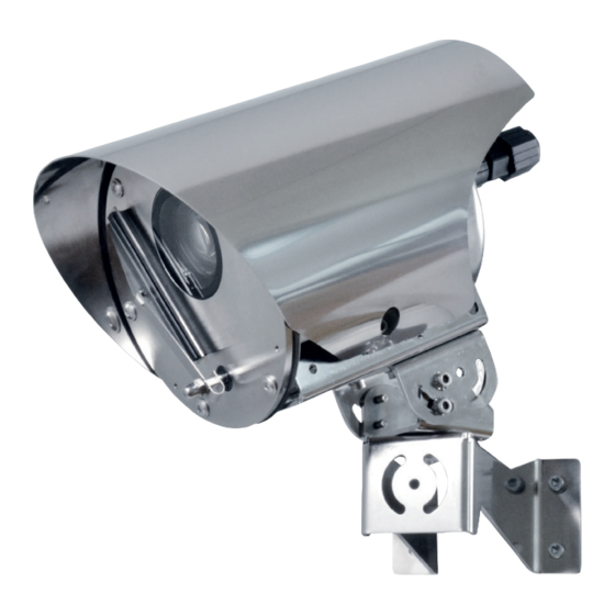
    5.3 Kennzeichnung des Produkts Siehe das Label auf dem Produkt. 5.1 Beschreibung und Bezeichnung des Produktes NVX ist eine Super low-light Full HD IP-Kamera mit hohen korrosionsbeständigen Eigenschaften heraus. Die DELUX-Imaging- und Encodingtechnologie für Videoaufnahmen mit unglaublich brillanten Farben bei Tag und Nacht wurde integriert.
  • Seite 96: Versionen

    6 Versionen 7 Vorbereitung des Produktes auf den Gebrauch 6.1 Version mit integriertem Scheibenwischer Jede vom Hersteller nicht ausdrücklich genehmigte Veränderung führt zum Verfall Die Standardausführung des Produkts wird mit der Gewährleistungsrechte. eingebautem Scheibenwischer geliefert. 7.1 Entfernen der Verpackung Bei der Lieferung des Produktes ist zu prüfen, ob die Verpackung intakt ist oder offensichtliche Anzeichen von Stürzen oder Abrieb aufweist.
  • Seite 97: Auf Die Installation Vorbereitende Tätigkeiten

    7.4 Auf die Installation 7.4.1 Befestigung an Wand, Geländer oder Decke vorbereitende Tätigkeiten Das Produkt ist für die Montage an der Wand, am Geländer oder an der Decke geeignet. ACHTUNG! Die Installation und Wartung der Vorrichtung ist technischen Fachleuten Die Befestigungshalterung (01) auf der Oberfläche vorbehalten.
  • Seite 98 Abb. 6 Befestigung an der Brüstung. Abb. 7 Deckenbefestigung. Bei der Montage an der Decke ist das Sonnenschutzdach abzumontieren. MNVCNVX_1903_DE...
  • Seite 99: Montageoptionen

    7.4.2 Montageoptionen Das Produkt kann in den nachfolgend angegebenen Positionen installiert werden. Der vertikale Neigungsbereich des Gehäuses reicht von -90° bis 0°. Abb. 10 Beispiel Geländermontage, Vertikale Drehung, 0°. Abb. 8 Beispiel Wandmontage, Vertikale Drehung, 0°. Abb. 11 Beispiel Geländermontage, Vertikale Drehung, -90°. Abb.
  • Seite 100 Das Produkt kann mit einer Kette oder einem Bei der Option der Deckenmontage muss Metalldraht festgemacht werden, um so einem das Sonnenschutzdach entfernt werden. Herunterfallen der Kamera vorzubeugen, sollte die Halterung nachgeben. Hierzu kann das Loch verwendet werden, siehe Abbildung (Abb. 14, Seite  14).
  • Seite 101: Installation

    Auf der Rückseite des Produkts befinden sich Alle nicht angeschlossenen Drähte sind Festanschlüsse. Die Steckverbinder müssen elektrisch zu isolieren. von der Kabelseite aus verkabelt werden (lose Steckverbinder). VIDEOTEC empfiehlt, vor der endgültigen Montage am Installationsort die Ethernet CONN 1 CONN 2 Konfiguration und die Leistungen des Gerätes zu prüfen.
  • Seite 102: Verkabelung Der Losen Steckverbinder (Netzteil, I/O)

    8.2.1 Verkabelung der losen Die am Pin 1 und 2 des Steckverbinders Steckverbinder (Netzteil, I/O) 2 angewandte Spannungspolarität ist irrelevant. CONN 1 CONN 2 Die Erdung ist nicht vorgesehen, da sie das Produkt nicht benötigt, wenn es mit 24Vac oder 24VVdc gespeist wird. Empfohlen wird die Verwendung von Kabeln mit folgenden Eigenschaften: •...
  • Seite 103: Anschluss Der Relais

    Die vorhandenen Schrauben der Klemmen (04) im Bevor die losen Steckverbinder an den vorderen Bereich des Steckverbinders lösen. Die entsprechenden Steckverbindern auf der Rückseite Leiter einführen und diese durch Anziehen der des Gehäuses befestigt werden, sicherstellen, dass Schrauben befestigen. Den Steckverbinderkorpus die TAP-Anschlüsse übereinstimmen.
  • Seite 104: Verkabelung Des Losen Steckverbinders (Ethernet)

    8.2.3 Verkabelung des losen Das Abschirmgeflecht an den geschirmten Steckverbinders (Ethernet) Steckverbinder RJ45 anschließen. Empfohlen wird die Verwendung von Ethernetkabeln mit den folgenden Eigenschaften: • SF/UTP • Kategorie 5E (oder höher) • 4 Paare (PoE+) • Durchmesser: von 5mm bis zu 6mm Abb.
  • Seite 105: Anschluss Des Ethernet-Kabels

    9 Einschaltung 8.2.4 Anschluss des Ethernet-Kabels Das Abschirmgeflecht des Ethernetkabels Sicherstellen, das die Einheit und die muss benutzerseitig stets geerdet sein. anderen Bauteile der Anlage korrekt Einen geschirmten Steckverbinder RJ45 geschlossen sind, um den Kontakt mit verwenden. Das Abschirmgeflecht an unter Spannung stehenden Bauteilen zu den geschirmten Steckverbinder RJ45 verhindern.
  • Seite 106: Konfiguration

    Sie im Handbuch, das sich auf die installierte Abb. 29 Firmware-Version bezieht. Das Handbuch ist auf der Produktwebseite in www.videotec.com verfügbar. Die montierte Düse und Halterung befestigen. Hierzu eines der Zusatzlöcher (01), die sich an der Gehäusevorderseite befinden, verwenden. Die Schraube und die Unterlegscheibe (02) festziehen.
  • Seite 107: Bügelhalterung Für Led-Scheinwerfer

    11.2 Bügelhalterung für LED- 11.5 Massive Mastschelle Scheinwerfer Für die Installation der LED-Scheinwerfer von VIDEOTEC muss das Gerät mit einer Bügelhalterung ausgestattet werden. Abb. 34 11.6 Gegenplatte Abb. 31 11.3 LED- Scheinwerfer Die Gegenplatte kann für die Wand- oder Deckenmontage verwendet werden, auch für Anwendungen mit Rohr.
  • Seite 108: Frontaler Staubschutzschild

    11.7 Frontaler Staubschutzschild 12.2 Öffnen und Schließen des Gehäuses Um einige Wartungsarbeiten durchzuführen, muss das Gehäuse geöffnet werden. Den vorderen Schlitten vorsichtig entfernen. Darauf achten, die inneren Verbindungskabel nicht zu beschädigen. Die Verschlussschraube lösen und den mit der Gehäusevorderseite verbundenen Schlitten entnehmen.
  • Seite 109: Beschreibung Der Gehäuseplatine

    12.3 Beschreibung der 12.4 Sicherung austauschen Gehäuseplatine ACHTUNG! Damit ein ständiger Brandschutz garantiert wird, sind die BESCHREIBUNG DER PLATINE Sicherungen nur in dem gleichen Typ und Verbinder/ Funktion Wert zu ersetzen. Die Sicherungen sind nur Klemme von Fachleuten zu ersetzen. Sicherung Im Bedarfsfall kann die Sicherung der Karte der Reset-Dipschalter...
  • Seite 110: Factory Default

    13 Reinigung 12.5 Factory Default Wenn die Factory-Default-Prozedur einmal Die Häufigkeit der Eingriffe hängt von der abgeschlossen ist, muss die Einheit wie Umgebung ab, in der die Einheit verwendet im entsprechenden Kapitel beschrieben wird. konfiguriert werden (10.1 Vorgegebene IP- 13.1 Fensterreinigung Adresse, Seite 20).
  • Seite 111: Technische Daten

    15 Technische Daten 15.5 Netzwerk Ethernet-Verbindung: 100 Base-TX 15.1 Allgemeines Verbinder: RJ45 Einfache Montage durch Schnellanschlüsse 15.6 Video Schnelle Einrichtung und Setup Video-Encoder 15.2 Mechanik • Kommunikationsprotokoll: ONVIF, Profil S und Hergestellt aus rostfreiem Stahl AISI 316L Profil Q Langloch für die Sicherheitskette •...
  • Seite 112: Kamera

    15.8 Kamera 15.9 Umgebung Day/Night Full HD 30x Montage für den Innen- und Außenbereich Auflösung: Full HD 1080p (1920x1080pixel) Betriebstemperatur Image Sensor: 1/2.8" Exmor™ R CMOS sensor • Version mit 24Vac- oder 24Vdc-Spannungsversorg ung: von -40°C bis zu +65°C Effektive Pixel: ca. 2.38 Megapixels •...
  • Seite 113: Technische Zeichnungen

    16 Technische Zeichnungen Die Maße sind in Millimetern angegeben. Ø 168 268.2 Ø 65 330.7 Abb. 41 NVX, Wandbefestigung. Ø 8.5 Ø 168 268.2 Ø 65 Abb. 42 NVX, befestigung an der Brüstung. MNVCNVX_1903_DE...
  • Seite 114 Ø 65 243.4 Ø 168 188.9 Ø 8.5 Abb. 43 NVX, deckenbefestigung. Headquarters Italy Videotec S.p.A. France Videotec France SARL Via Friuli, 6 - I-36015 Schio (VI) - Italy Immeuble Le Montreal, 19bis Avenue du Québec, ZA de Courtaboeuf Tel. +39 0445 697411 - Fax +39 0445 697414 91140 Villebon sur Yvette - France Email: info@videotec.com...
  • Seite 115 РУССКИЙ Камера FULL HD с защитой от коррозии и технологией DELUX Русский - Руководство по эксплуатации...
  • Seite 117 Комплект оборудования Р У С С К И Й 1 О настоящем руководстве ..................... 5 1.1 Типографские условные обозначения ........................5 2 Примечания в отношении авторского права и информация о торговых марках..5 3 Примечания по защите данных ................... 5 3.1 Общая...
  • Seite 118 11.4 Адаптер для крепления на угол ..........................21 11.5 Адаптер для установки на стойке ..........................21 11.6 Пластина крепления ...............................21 11.7 Передний козырек для защиты от пыли .......................22 12 Техническое обслуживание ....................22 12.1 Снятие козырька ................................22 12.2 Открытие и закрытие кожуха .............................22 12.3 Описание...
  • Seite 119: О Настоящем Руководстве

    VIDEOTEC S.p.A. производит устройства видеонаблюдения исключительно для ОПАСНОСТЬ! профессионального применения. Продукция Горячая поверхность. VIDEOTEC S.p.A. может использоваться в Избегайте контакта. При контакте с технических областях для самых разных целей: горячими поверхностями существует от контроля за городской безопасностью до риск получения ожогов.
  • Seite 120: Функции Безопасности, Которые Могут Быть Активированы В Устройстве

    первой же учетной записи пользователя. На этом этапе устройство переходит в режим OperationalState и этих устройств автоматически обновлялась активируется только после ввода учетных данных. через Интернет. VIDEOTEC S.p.A. со временем может выпускать обновления мер безопасности Ответственность за использование устройства в для своих устройств, которые должны быть...
  • Seite 121: Правила Техники Безопасности

    4 Правила техники • Перед тем, как приступить к выполнению любых операций, убедитесь в том, что источник безопасности питания устройства отключен. • Не используйте кабели, которые кажутся ПРЕДУПРЕЖДЕНИЕ! Система изношенными или старыми. электропитания, к которой подключается • Никогда и ни при каких обстоятельствах не устройство, должна...
  • Seite 122 • Обращайтесь с устройством осторожно, чтобы • Это устройство Класса А. При установке избежать случайного контакта, острых углов и в жилых помещениях данное устройство кромки. может вызывать радиопомехи. В таком случае пользователю может потребоваться • Развязка цепей обеспечивается внешними предпринять соответствующие меры. устройствами, например, защитным...
  • Seite 123: Обозначение

    5.3 Маркировка изделия См. ярлык на изделии. 5.1 Описание и обозначение типа устройства Модель NVX является камерой FULL HD, созданной для работы в условиях сверхнизкой освещенности и имеющей высокую устойчивость к коррозии. В данной камере реализована технология передачи изображения и кодирования DELUX, которая...
  • Seite 124: Модели

    6 Модели 7 Подготовка устройства к использованию 6.1 Модель со встроенным стеклоочистителем Любое изменение, которое выполняется без разрешения, явным образом В стандартной версии изделие оснащено предоставленного производителем, встроенным стеклоочистителем. аннулирует гарантию. 7.1 Распаковка При получении устройства убедитесь, что упаковка не повреждена...
  • Seite 125: Подготовительные Работы Перед Установкой

    7.4 Подготовительные работы 7.4.1 Установка на стене, парапете или потолке перед установкой Изделие можно установить на стене, парапете или потолке. ПРЕДУПРЕЖДЕНИЕ! Установка и обслуживание устройства Закрепите кронштейн для фиксации (01) на должны осуществляться только конечной поверхности установки. специализированным персоналом. Установите опору кожуха (03) на кожух с помощью четырех...
  • Seite 126 Рис. 6 Крепление к парапету. Рис. 7 Крепление на потолок. При установке на потолок необходимо снять козырек. MNVCNVX_1903_RU...
  • Seite 127: Варианты Установки

    7.4.2 Варианты установки Устройство может устанавливаться в представленных ниже положениях. Диапазон вертикального наклона кожуха составляет -90 °- 0 °. Рис. 10 Пример установки на парапете, вертикальное перемещение, 0°. Рис. 8 Пример установки на стене, вертикальное перемещение, 0°. Рис. 11 Пример установки на парапете, вертикальное перемещение, -90°.
  • Seite 128 Изделие можно закрепить при помощи цепи или При установке на потолок козырек металлической проволоки, чтобы предотвратить необходимо снять. падение камеры в случае разрушения опоры. Для этой цели можно использовать отверстие, показанное на рисунке (Рис. 14, страница 14). Рис. 12 Пример установки на потолок, вертикальное Рис.
  • Seite 129: Монтаж

    Быстроразъемное подключение к устройству облегчает установку. Все неподключенные провода должны быть На задней стороне устройства закреплены изолированы. разъемы. Подключение к разъемам должно осуществляться со стороны кабеля (штепсельные VIDEOTEC настоятельно рекомендует разъемы). проверить конфигурацию и эксплуатационные характеристики Ethernet CONN 1 CONN 2 устройства...
  • Seite 130: Кабельная Проводка Для Штепсельного Соединения (Источник Питания, I/O)

    8.2.1 Кабельная проводка для Полярность напряжения на контактах 1 и штепсельного соединения (источник 2 разъема 2 не имеет значения. питания, I/O) Заземление не предусмотрено, CONN 1 CONN 2 поскольку изделию оно не требуется, так как для его питания используется 24Vac или...
  • Seite 131: Подключение Реле

    Ослабьте винты на клеммах (04) лицевой стороны Перед тем как подсоединить штепсельные разъема, вставьте провода и зафиксируйте их, разъемы к соответствующим разъемам на задней затянув винты. Закрепите корпус разъема (03) на стороне кожуха, убедитесь, что TAP плотно лицевой стороне с помощью зажимов (05), затянув прилегает.
  • Seite 132: Кабельная Проводка Для Штепсельного Разъема (Ethernet)

    8.2.3 Кабельная проводка для Подсоедините кабельную оплетку к штепсельного разъема (Ethernet) экранированному разъему RJ45. Настоятельно рекомендуется использовать Ethernet-кабели со следующими характеристиками: • SF/UTP • Категория 5E (или выше) • 4 витые пары (PoE+) • Диаметр: от 5mm до 6mm Рис. 24 Подсоедините...
  • Seite 133: Подключение Ethernet-Кабеля

    9 Включение 8.2.4 Подключение Ethernet-кабеля Оплетка кабеля Ethernet со стороны Убедитесь в том, что устройство и прочие пользователя должна быть элементы системы снабжены защитными постоянно заземлена. Используйте кожухами, исключающими возможность экранированный разъем RJ45. контакта с токопроводящими Подсоедините кабельную оплетку к компонентами.
  • Seite 134: Конфигурация

    Закрепите собранное сопло и опору, используя версии прошивки, которое доступно на нашем одно из дополнительных отверстий (01) на веб-сайте www.videotec.com. лицевой стороне кожуха. Затяните винт с шайбой (02). Вставьте подающую трубку в сопло (03). Закрепите подающую трубку на опоре с помощью...
  • Seite 135: Опорный Кронштейн Для Светодиодной Подсветки

    11.2 Опорный кронштейн для 11.5 Адаптер для установки на светодиодной подсветки стойке Для установки светодиодных осветителей VIDEOTEC, на устройство необходимо установить опорный кронштейн. Рис. 34 Рис. 31 11.6 Пластина крепления 11.3 Светодиодный осветитель Пластину крепления можно использовать для установки на стену или потолок, а также на...
  • Seite 136: Передний Козырек Для Защиты От Пыли

    11.7 Передний козырек для 12.2 Открытие и закрытие защиты от пыли кожуха Для выполнения ряда работ по техническому обслуживанию необходимо открыть кожух. Осторожно открутите направляющую на лицевой стороне. Соблюдайте осторожность, чтобы не повредить внутренние соединительные кабели. Отвинтите стопорные винты и снимите направляющую, закрепленную...
  • Seite 137: Описание Платы Кожуха

    12.3 Описание платы кожуха 12.4 Замена предохранителя ОПИСАНИЕ ПЛАТЫ ПРЕДУПРЕЖДЕНИЕ! Для обеспечения постоянной защиты от риска возгорания Разъем/ Функция Клемма при замене предохранителей следует использовать предохранители Предохранитель того же типа и номинала. Только DIP-переключатель сброса обслуживающий персонал может Табл. 5 проводить...
  • Seite 138: Factory Default

    13 Очистка 12.5 Factory Default После установки заводских настроек Частота операций зависит от среды устройство должно быть настроено так, эксплуатации изделия. как описано в соответствующей главе ( 13.1 Очистка стекла 10.1 IP-адрес по умолчанию, страница  20). Не используйте этиловый спирт, 12.5.1 Factory Default (модель...
  • Seite 139: Технические Характеристики

    15 Технические 15.5 Сеть характеристики Ethernet подключение: 100 Base-TX Разъем: RJ45 15.1 Общие сведения 15.6 Видео Простая установка благодаря быстроразъемному Видеокодер подключению • Протокол связи: ONVIF, Profile S и Profile Q Быстрая настройка и установка • Конфигурация устройства: TCP/IPv4-IPv6, 15.2 Механические хар. UDP/IPv4-IPv6, HTTP, HTTPS, NTP, DHCP, WS- DISCOVERY, DSCP, IGMP (Многоадресный), SOAP, Конструкция...
  • Seite 140: Камеры

    15.8 Камеры 15.9 Окружающая среда Day/Night Full HD 30x Для установки внутри помещений и наружной установки Разрешение: Full HD 1080p (1920x1080pixel) Рабочая температура Датчик изображения: 1/2.8" Exmor™ R CMOS sensor • Версия с питанием 24Vac переменного тока или Эффективные пиксели: приблизительно 2.38 24Vdc постоянного...
  • Seite 141: Технические Чертежи

    16 Технические чертежи Размеры указаны в миллиметрах. Ø 168 268.2 Ø 65 330.7 Рис. 41 NVX, установка на стену. Ø 8.5 Ø 168 268.2 Ø 65 Рис. 42 NVX, крепление к парапету. MNVCNVX_1903_RU...
  • Seite 142 243.4 Ø 168 188.9 Ø 8.5 Рис. 43 NVX, крепление на потолок. Headquarters Italy Videotec S.p.A. France Videotec France SARL Via Friuli, 6 - I-36015 Schio (VI) - Italy Immeuble Le Montreal, 19bis Avenue du Québec, ZA de Courtaboeuf Tel. +39 0445 697411 - Fax +39 0445 697414 91140 Villebon sur Yvette - France Email: info@videotec.com...
  • Seite 144 Email: info@videotec.com Tel. +33 1 60491816 - Fax +33 1 69284736 Email: info.fr@videotec.com Asia Pacific Videotec (HK) Ltd Americas Videotec Security, Inc. Flat 8, 19/F. On Dak Industrial Building, No. 2-6 Wah Sing Street Gateway Industrial Park, 35 Gateway Drive, Suite 100 Kwai Chung, New Territories - Hong Kong Plattsburgh, NY 12901 - U.S.A.

Inhaltsverzeichnis