Herunterladen Inhalt Inhalt Diese Seite drucken
Inhaltsverzeichnis

Werbung

Verfügbare Sprachen
  • DE

Verfügbare Sprachen

  • DEUTSCH, seite 53
Nice
DPRO500
Control unit
EN - Instructions and warnings for installation and use
IT - Istruzioni ed avvertenze per l'installazione e l'uso
FR - Instructions et avertissements pour l'installation et l'utilisation
ES - Instrucciones y advertencias para la instalación y el uso
DE - Installierungs-und Gebrauchsanleitungen und Hinweise
PL - Instrukcje i ostrzeżenia do instalacji i użytkowania
NL - Aanwijzingen en aanbevelingen voor installatie en gebruik
RU - Инструкции и предупреждения по монтажу и эксплуатации

Werbung

Inhaltsverzeichnis
loading

Inhaltszusammenfassung für Nice DPRO500

  • Seite 1 Nice DPRO500 Control unit EN - Instructions and warnings for installation and use IT - Istruzioni ed avvertenze per l’installazione e l’uso FR - Instructions et avertissements pour l’installation et l’utilisation ES - Instrucciones y advertencias para la instalación y el uso DE - Installierungs-und Gebrauchsanleitungen und Hinweise PL - Instrukcje i ostrzeżenia do instalacji i użytkowania...
  • Seite 3 8,2 kΩ brown - 12V DC green - Segnale Signal white - GND/0V...
  • Seite 4 encoder open close photo safe com sw only open with limit precl switch close STOP 8k2/OSE encoder open close photo safe com sw only with open limit precl switch close STOP 8k2/OSE...
  • Seite 5 (Annex I to this manual) cannot be used. As a result, the installer in turn becomes the manufacturer of the product and must comply with the provisions of Regulation No. 305/2011 and its harmonised standard EN 13241-1. In this case the product must be considered as “partly-completed machinery” and the “Declaration of Conformity” of Annex II can be used (for inclusion in the technical documentation). • “Low Voltage” Directive: Special warnings regarding the fitness of use of this product in relation to the “Low Voltage” Directive. This product meets the requirements in the “Low Voltage” Directive, if used for the use and in the configurations specified in this instruction manual and in combination with the items in the Nice S.p.A. product catalogue. If the product is used in unspecified configurations or with other unspecified products, the requirements may not be guaranteed; the use of the product in such circumstances is prohibited until the installer has verified compliance with the specified requirements of the directive. English – 1...
  • Seite 6 • “Electromagnetic compatibility” Directive: Special warnings regarding the fitness of use of this product in relation to the “Electromagnetic compatibility” Directive. This product has been subjected to electromagnetic compatibility tests in the most critical situations of use and in the configurations specified in this instruction manual and in combination with the items in the Nice S.p.A. product catalogue. If the product is used in unspecified configurations or with other unspecified products, the electromagnetic compatibility may not be guar- anteed; the use of the product is prohibited in such circumstances until the installer has verified compliance with the specified requirements of the directive. Installation criteria and special warnings in connection with essential requirements • When installed correctly, this product meets the essential requirements laid down in Regulation No. 305/2011 according to the requirements in harmonised standard EN 13241-1, as indicated in Table 1 and in the European directive on “Machinery” 2006/42/EC. • Release of dangerous substances: The product does not contain and/or release hazardous substances in accordance with the requirements of EN 13241-1, 4.2.9 and accord-...
  • Seite 7: Inhaltsverzeichnis

    DPRO500 PRODUCT DESCRIPTION AND INTENDED USE ENGLISH The DPRO500 control unit is designed to control electromechanical actuators for automating gates, sectional doors or shutters. CAUTION! – All uses other than the intended use described and use Instructions translated from Italian...
  • Seite 8: Limit Switch

    - three-phase 4 x 1 mm 5 m (note 1) - single-phase 3 x 0,75 mm 2 m (note 1) MOTOR cable special cables for Nice gearmotors are on sale as 5 - 7 - 11 m accessories. for other brands, contact the motor manufacturer Cable for FLASHING LIGHT with aerial 2 x 1 mm (for 230 V AC flashing light)
  • Seite 9: Electrical Connections

    To select the 230 V single-phase power supply, observe the instructions card that adds two outputs to voltage-free contacts. These outputs can be specified in Chapter 3.2 properly programmed with the Nice Oview programmer. For a description and instructions on programming the available functions, see the NDA040 3.1 - Connecting the three-phase power supply cable accessory board manual.
  • Seite 10: Connecting A Radio Receiver

    Multiple devices, even of different types, can be connected to the STOP Press and hold the 3” SAFETY EDGE input if appropriately organised: STOP button for 3 sec. - NO devices: connect the 8.2 kΩ resistor in parallel to the device; until the green and red - NC devices: connect the 8.2 kΩ resistor in series to the device; leds remain lit - You can connect multiple NC devices “in series” with each other without quantity limits;...
  • Seite 11: Operating Modes

    6.1.1 - Signals when switching ON 3.12 - Oview programming unit When the DPRO500 control unit is switched ON, the reaction of the green OK Using the Oview programming unit allows you to manage the installation, L2 led and the red WARNING L1 LED is important, as shown in Table 4. In...
  • Seite 12: Diagnostics

    This “indicator” functions in the following way: - off when the safety chain is open (ALT inp, red STOP button, thermal protec- tion or release) - flashes 0.5 s ON, 0.5 s OFF when it works properly - shows the same diagnostics as the red L1 WARNING LED when there are “serious errors” (Paragraph 6.2). Setting the pause time for automatic closing 1 Set DIP switches 3 and 4 to ON.
  • Seite 13: Disposal Of The Product

    10 flashes - short pause Error in movement time-out The default setting for the movement time-out is 60 seconds. Check 10 flashes - long pause whether there are any obstructions to the movement of the gate or whether the gate has actually performed the movement. Check whether the duration of the timer has been changed (using the Oview programmer if available). Repeat the recognition of the Open- ing and Closing positions.
  • Seite 14: Technical Specifications

    TECHNICAL SPECIFICATIONS WARNINGS: • All technical specifications stated herein refer to an ambient temperature of 20° C (± 5° C). • Nice S.p.A. reserves the right to apply modifications to products at any time when deemed necessary, maintaining the same intended use and functionality. Type Control unit for single-phase or three-phase motors with Nice mechanical or electronic limit switches Power supply Three-phase Single-phase 3~400V AC / 3~230V AC (+10% - 10%) 50/60Hz 1~230V AC (+10% - 10%) 50/60Hz Motor max power 2.2kW...
  • Seite 15 “partly completed machinery” Note: the contents of this declaration correspond to that stated in the official document filed in the offices of Nice S.p.A. and, in particular, the latest version thereof available prior to the printing of this manual. The text herein has been re-edited for editorial purposes. A copy of the original declaration can be requested from Nice S.p.A.
  • Seite 17 - L’installazione completa di questo prodotto, così come descritta in questo manuale di istruzioni e per alcuni tipi di uso (ad esempio escluso l’uso solo per veicoli), possono farlo rientrare nel campo di applicazione del Regolamento 305/2011 e della relativa norma armonizzata EN 13241-1. - È necessario applicare i criteri di installazione necessari affinché il prodotto risponda ai requisiti essenziali del Regolamento 305/2011; chi esegue l’installazione dovrà verificare ed assicurarsi che tutti questi criteri siano stati scrupolosamente rispettati. - Potrebbero non essere garantiti i requisiti essenziali se il prodotto è installato e usato senza il rispetto di uno o più di questi criteri. È vietato l’uso del prodotto in queste situazioni finche chi esegue l’installazione non abbia verificato la rispondenza ai requisiti previsti dalla direttiva; in questo caso l’etichetta “ES13241-1.4870” applicata sul prodotto dovrà essere immediatamente rimossa e non potrà essere utilizzata la “Dichiarazione CE di Conformità” dell’allegato I presente in questo manuale. Come conseguenza chi esegue l’installazione diventa, a sua volta il fabbricante del prodotto e dovrà rispettare quanto previsto dal Regolamento 305/2011 e della relativa norma armonizzata EN 13241- 1. In questo caso il prodotto deve essere considerato come “quasi macchina” e potrà essere utilizzato (per essere inserita nel fascicolo tecnico), la “Dichiarazione di Conformità” dell’allegato II. • Direttiva “Bassa Tensione”: Avvertenze particolari sull’idoneità all’uso di questo prodotto in relazione alla Direttiva “Bassa Tensione”. Questo prodotto risponde ai requisiti previsti dalla Direttiva “Bassa Tensione” se impiegato per l’uso e nelle configurazioni previste in questo manuale di istruzioni ed in abbina- mento con gli articoli presenti nel catalogo prodotti di Nice S.p.A. Potrebbero non essere garantiti i requisiti se il prodotto è usato in configurazioni o con altri prodotti non previsti; è vietato l’uso del prodotto in queste situazioni finché chi esegue l’installazione non abbia verificato la rispondenza ai requisiti previsti dalla direttiva. Italiano – 1...
  • Seite 18 • Direttiva “Compatibilità Elettromagnetica”: Avvertenze particolari sull’idoneità all’uso di questo prodotto in relazione alla Direttiva “Compatibilità Elettromagnetica”. Questo prodotto è stato sottoposto alle prove relative alla compatibilità elettromagnetica nelle situazioni d’uso più critiche, nelle configurazioni previste in questo manuale di istruzioni ed in abbinamento con gli articoli presenti nel catalogo prodotti di Nice S.p.A. Potrebbe non essere garantita la compatibilità elettromagnetica se il prodotto è usato in configurazioni o con altri prodotti non previsti; è vieta- to l’uso del prodotto in queste situazioni finché chi esegue l’installazione non abbia verificato la rispondenza ai requisiti previsti dalla direttiva. Criteri d’installazione e avvertenze particolari in relazione ai requisiti essenziali • Questo prodotto, se installato correttamente, rispetta i requisiti essenziali previsti dal Regolamento 305/2011 secondo quanto richiesto della norma armonizzata EN 13241-1, così come indicato nella Tabella 1 e dalla Direttiva europea sulle “macchine” 2006/42/CE. • Rilascio di sostanze pericolose: Il prodotto non contiene e/o non rilascia sostanze pericolose in conformità a quanto previsto dalla norma EN 13241-1, punto 4.2.9 e secondo...
  • Seite 19 DPRO500 DESCRIZIONE DEL PRODOTTO E DESTINAZIONE D’USO ITALIANO La centrale DPRO500 è destinata al comando di attuatori elettromeccanici per l'automazione di cancelli, porte sezionali o serrande. AT TENZIONE! – Qualsiasi altro uso diverso da quello de scritto e in con- Istruzioni originali dizioni am bientali diverse da quelle riportate in questo manuale è da...
  • Seite 20 4 x 1 mm 5 m (nota 1) - monofase 3 x 0,75 mm 2 m (nota 1) Cavo MOTORE per motoriduttori Nice, cavi dedicati in vendita come 5 - 7 - 11 m accessori. per marchi diversi, richiedere al produttore del motoriduttore Cavo LAMPEGGIANTE con antenna 2 x 1 mm...
  • Seite 21: Collegamenti Elettrici

    – Alt in chiusura Per istruzioni su come effettuare la programmazione e descrizione delle fun- zioni disponibili, consultare le schede funzioni Oview per DPRO500. 3.6 - Ingresso STOP SAFETY EDGE ALT - ingresso per dispositivi che arrestano la manovra in corso; collegare La funzione dell’ingresso SAFETY EDGE è provocare l’arresto immediato della...
  • Seite 22: Collegamento Di Un Ricevitore Radio

    collegato e provoca uno “STOP” quando si verifica una qualsiasi variazione Impostare dip switch rispetto allo stato appreso. 1-2-3-4 su ON = i led verde e rosso iniziano a Con opportuni accorgimenti, è possibile collegare all’ingresso STOP SAFETY emettere lampeggi veloci EDGE più di un dispositivo, anche di tipo diverso: - dispositivi NA: collegare la resistenza da 8.2 kΩ in parallelo al dispositivo; Mantenere premuto il - dispositivi NC: collegare la resistenza da 8.2 kΩ in serie al dispositivo; 3” - è possibile collegare più dispositivi NC “in serie” tra loro senza limiti di quantità; tasto STOP per 3 sec. - se sono presenti più dispositivi, tutti devono essere collegati “in cascata” con fino a quando i led verde e rosso si acccendono una sola resistenza di terminazione da 8.2 kΩ;...
  • Seite 23: Modalità Di Funzionamento

    3.12 - Unità di programmazione Oview L’utilizzo dell’unità di programmazione Oview consente una completa e rapida 6.1 - Approfondimenti gestione della fase d’installazione, di manutenzione e di diagnosi dell’intera automazione. 6.1.1 - Segnalazioni all'accensione È possibile collegare Oview alla centrale, tramite l’interfaccia IBT4N utilizzando All’accensione della centrale DPRO500, il comportamento dei led L2 OK verde un cavo bus con 4 fili elettrici all’interno. e L1 WARNING rosso, è significativo, come illustrato in Tabella 4. In particolare, Per accedere al connettore BusT4, è necessario aprire il box della centrale, le informazioni segnalate sono: inserire il connettore IBT4N nell’apposita sede e poi collegare il programmatore - Se l’acquisizione delle posizioni di apertura e chiusura è corretta;...
  • Seite 24: Diagnostica

    Per modificare il valore del tempo pausa portare il dip 3 e 4 on OFF e poi nuo- coperchio, forandolo oppure esternamente alla centrale con una distanza vamente in ON. A questo punto è necessario ripetere la sequenza di apertura, massima di 2 m da quest’ultima. tempo pausa, chiusura. ATTENZIONE! - L’uscita non è protetta da cortocircuito. ATTENZIONE! - Quando il DIP switch 4 viene portato in posizione OFF, il Questa “spia” funziona nel modo seguente: tempo pausa è cancellato. - spenta quando la catena di sicurezza è aperta (ing ALT, pulsante STOP rosso, termica o sblocco) - lampeggia 0.5s ON, 0.5s OFF quando funziona correttamente - riporta la stessa diagnostica del led L1 WARNING rosso quando ci sono...
  • Seite 25: Cosa Fare Se

    10 lampeggi - pausa corta Errore time-out manovra Il valore di default del time-out manovra è 60 secondi. Verificare che 10 lampeggi - pausa lunga non ci siano impedimenti al movimento del cancello e che il cancello abbia effettivamente eseguito il movimento. Verificare (col program- matore Oview se disponibile) se il durata del timer è stata modificata. Eseguire nuovamente l’apprendimento delle posizioni di Apertura e Chiusura. Nota – la segnalazione diagnostica con lampeggio dei led si interrompe nel momento in cui viene dato un comando alla centrale. La segnalazione diagnostica utilizzando un lampeggiante esterno* continua per due sequenze di lampeggi (es.
  • Seite 26: Caratteristiche Tecniche Del Prodotto

    CARATTERISTICHE TECNICHE DEL PRODOTTO AVVERTENZE: • Tutte le caratteristiche tecniche riportate, sono riferite ad una temperatura ambientale di 20°C (± 5°C). • Nice S.p.A. si riserva il diritto di apportare modifiche al prodotto in qualsiasi momento lo riterrà necessario, mantenendone comunque la stessa funzionalità e destinazione d’uso. Tipologia Centrale di comando per motori monofase o trifase con finecorsa meccanico o elettronico Nice Tensione di alimentazione Trifase Monofase 3~400Vac / 3~230Vac (+10% - 10%) 50/60Hz 1~230Vac (+10% - 10%) 50/60Hz Potenza max motore 2.2kW...
  • Seite 27 “quasi macchina” Nota - Il contenuto di questa dichiarazione corrisponde a quanto dichiarato nel documento ufficiale depositato presso la sede di Nice S.p.A., e in particolare, alla sua ultima revisione disponibile prima della stampa di questo manuale. Il testo qui presente è stato riadattato per motivi editoriali.
  • Seite 29 RECOMMANDATIONS GÉNÉRALES : SÉCURITÉ - INSTALLATION - UTILISATION (instructions traduites de l’italien) Les recommandations suivantes sont transcrites directement des réglementations et, dans la mesure du possible, applicables au produit en question ATTENTION Instructions importantes pour la sécurité. Il est important de suivre toutes les instructions fournies étant donné qu’une installation incorrecte est susceptible de provoquer des dommages graves ATTENTION Instructions importantes pour la sécurité.
  • Seite 30 • Directive « Basse tension » : Recommandations particulières sur l’aptitude à l’emploi de ce produit en ce qui concerne la Directive « Basse tension ». Le produit respecte les normes imposées par la Directive Basse tension lorsqu’il est utilisé selon les configurations prévues dans le présent manuel et avec les articles composant le catalogue de Nice S.p.A. Ces conditions pourraient ne pas être garanties si le produit est utilisé dans des configurations ou avec d’autres produits non prévus à cet effet. L’utilisation du produit dans ces situations est interdite tant que l’installateur n’a pas vérifié leur conformité à la Directive. • Directive « Compatibilité électromagnétique » : Recommandations particulières sur l’aptitude à l’emploi de ce produit en ce qui concerne la Directive « Compatibilité électromagnétique ». Le produit respecte les critères relatifs aux essais de compatibilité électromagnétique dans les conditions d’utilisation les plus critiques, dans des configurations prévues dans le présent manuel et avec les articles composant le catalogue de Nice S.p.A. La compatibilité électromagnétique pourrait ne pas être garantie si le produit est utilisé dans des configurations ou avec d’autres produits non prévus à cet effet. L’utilisation du produit dans ces situations est interdite tant que l’installateur n’a pas vérifié si celles-ci sont conformes à la Directive. Consignes d’installation et recommandations particulières sur les conditions requises • En cas d’installation correcte, ce produit respecte les conditions stipulées dans le Règlement 305/2011 conformément aux prescriptions de la norme harmonisée EN 13241-1, comme l’indique le Tableau 1, et de la Directive européenne sur les « machines » 2006/42/CE. • Émission de substances dangereuses : Le produit ne contient ni n’émet de substances dangereuses, conformément à la norme EN 13241-1, par. 4.2.9 et selon la liste des subs- tances reprise sur le site de la Communauté européenne.
  • Seite 31: Description Du Produit Et Application

    DPRO500 DESCRIPTION DU PRODUIT ET APPLICATION FRANÇAIS La logique de commande DPRO500 est destinée à la commande des action- neurs électromécaniques pour l’automatisation de portails, portes sectionnelles ou volets. Instructions traduites de l’italien ATTENTION  ! – Toute utilisation autre que celle décrite et dans des conditions ambiantes différentes de celles indiquées dans cette notice Sommaire doit être considérée comme impropre et interdite !
  • Seite 32 Câble ALIMENTATION LOGIQUE DE COMMANDE - triphasé 4 x 1 mm 5 mètres (note 1) - monophasé 3 x 0,75 mm 2 mètres (note 1) Câble MOTEUR pour les opérateurs Nice, câbles vendus séparément. 5 - 7 - 11 mètres pour les autres marques, s’adresser au fabricant de l’opérateur. Câble de CLIGNOTANT avec antenne 2 x 1 mm (pour clignotant 230Vac) 10 m câble blindé RG58 (pour antenne) Câble de PHOTOCELLULE...
  • Seite 33: Raccordements Électriques

    OUT (CONNECTEUR POUR NDA040) - connecteur pour carte acces- Les bornes L1, L2, L3 et PE sont reliées à une fiche CEE de 16A. soire NDA040 qui ajoute deux sorties à contacts sans potentiel. Ces sorties peuvent être programmées à l’aide du programmateur Nice Oview. Pour 3.2 - Raccordement du câble d’alimentation monophasé toutes instructions sur la programmation et la description des fonctions dis- Pour effectuer le raccordement électrique, se référer à la fig. 4.
  • Seite 34: Raccordement D'un Récepteur Radio

    la manœuvre en cours, suivi d’une manœuvre de brève inversion. 3.9 - Effacement complet de la mémoire de la logique de commande D’autres dispositifs peuvent être raccordés à cette entrée, comme des barre palpeuses optiques (OSE) ou une sortie à résistance constante de 8.2 kΩ. Il est possible d’effacer toutes les données enregistrées et de rétablir la confi- guration d’origine. Pendant la phase de reconnaissance, la logique de commande détecte le type de dispositif connecté et provoque un arrêt en cas de modification par rapport Régler les micro- à l’état mémorisé. interrupteurs 1-2-3-4 En adoptant certaines solutions, on peut connecter à l’entrée STOP SAFETY sur ON = les led verte EDGE plus d’un dispositif, même de type différent : et rouge commencent à - dispositifs NO : raccorder la résistance de 8.2 kΩ en parallèle au dispositif.
  • Seite 35: Mode De Fonctionnement

    Pour utiliser Oview, il faut observer les consignes reprises dans la notice d’instructions d’Oview. À l’allumage de la logique de commande DPRO500, le comportement des Si la logique de commande est équipée d’un récepteur radio de la série OXI, en led L2 OK verte et L1 WARNING rouge, est significatif, comme illustré dans le...
  • Seite 36: Autres Fonctions

    Après les signalisations comme indiqué dans le tableau 4, la logique de com- 3 Une fois que cette position est atteinte, attendre un temps équivalent au mande DPRO500 indique les erreurs éventuelles par le diagnostic par le biais temps de pause de fermeture automatique désiré et donner une commande des led L2 OK et L1 WARNING. de fermeture. Le temps de pause de la fermeture automatique est à présent mémorisé.
  • Seite 37: Que Faire Si

    7 clignotements - pause courte Erreur de communication RS485 Vérifier la connexion du câble moteur-logique, notamment celle du 7 clignotements - pause prolongée Encodeur câble de l’encodeur (6 fils colorés). 8 clignotements - pause courte Erreur encodeur Vérifier la connexion du câble moteur-logique, notamment celle du 8 clignotements - pause prolongée câble de l’encodeur (6 fils colorés). Effectuer à nouveau la procédure de reconnaissance des positions d’Ouverture et de Fermeture. 9 clignotements - pause courte Erreur reconnaissance fin de Refaire une nouvelle fois la procédure de reconnaissance des posi- 9 clignotements - pause prolongée course tions d’Ouverture et de Fermeture. 10 clignotements - pause courte Erreur délai d’expiration La valeur par défaut du délai d’expiration de la manœuvre est de 10 clignotements - pause prolongée...
  • Seite 38: Mise Au Rebut

    étaient jetés dans la nature. Comme l’indique le symbole ci-contre, il est interdit de jeter ce produit avec les ordures ménagères. Procéder à la « collecte différenciée » des composants pour leur traitement conformément aux méthodes prescrites par les normes locales en vigueur ou restituer le produit au vendeur lors de l’achat d’un nouveau produit équivalent. Attention ! – les règlements locaux en vigueur peuvent prévoir de lourdes sanctions en cas d’élimination abusive de ce produit. CARACTÉRISTIQUES TECHNIQUES DU PRODUIT RECOMMANDATIONS : • Toutes les caractéristiques techniques indiquées se réfèrent à une température ambiante de 20 °C (+/- 5 °C). • La société Nice S.p.A. se réserve le droit d’apporter des modifications au produit à tout moment si elle le juge nécessaire, en garantissant dans tous les cas les mêmes fonctions et la même utilisation prévue. Typologie Logique de commande pour moteurs monophasés ou triphasés avec fin de course mécanique ou électronique Nice Tension d’alimentation Triphasé...
  • Seite 39 Remarque - Le contenu de cette déclaration de conformité correspond à ce qui est déclaré dans le document officiel, déposé au siège de Nice S.p.A., et en particulier à sa dernière révision disponible avant l’impression de ce manuel. Le présent texte a été réadapté pour des raisons d’édition.
  • Seite 41 ADVERTENCIAS GENERALES: SEGURIDAD - INSTALACIÓN - USO (instrucciones traducidas del italiano) Las siguientes advertencias se transcriben directamente de las Normas y se aplican, en la medida de lo posible, al producto en cuestión ATENCIÓN Instrucciones importantes para la seguridad. Seguir todas las instrucciones: una instalación incorrecta puede provocar daños graves ATENCIÓN Instrucciones importantes para la seguridad.
  • Seite 42 • Directiva “Baja Tensión”: Advertencias particulares sobre la idoneidad de este producto según la Directiva “Baja Tensión”. Este producto responde a los requisitos establecidos por la Directiva “Baja Tensión” si se destina al uso y a las configuraciones previstas en este manual de instrucciones, en com- binación con los artículos ilustrados en el catálogo de productos de Nice S.p.A. Podrían no estar garantizados los requisitos si el producto se utilizara en configuraciones o con productos no previstos; está prohibido el uso del producto en estas situaciones si el instalador no ha verificado la conformidad a los requisitos establecidos por la normativa. • Directiva “Compatibilidad Electromagnética”: Advertencias particulares sobre la idoneidad de este producto según la Directiva “Compatibilidad Electromagnética”. Este producto se ha sometido a pruebas de compatibilidad electromagnética en las situaciones de uso más críticas, en las configuraciones previstas en este manual de instrucciones y en combinación con los artículos ilustrados en el catálogo de productos de Nice S.p.A. Podría no estar garantizada la compatibilidad electromagnética si el producto se utilizara en configuraciones o con productos no previstos; está prohibido el uso del producto en estas situaciones si el instalador no ha verificado la conformidad a los requisitos establecidos por la normativa. Criterios de instalación y advertencias particulares en relación con los requisitos esenciales • Si se instala correctamente, este producto cumple con los requisitos esenciales previstos por el Reglamento 305/2011 según lo establecido por la norma armonizada EN 13241-1, como se indica en la Tabla 1, y por la Directiva europea sobre “Máquinas” 2006/42/CE. • Emisión de sustancias peligrosas: El producto no contiene ni emite sustancias peligrosas, considerando la norma EN 13241-1, punto 4.2.9 y la lista de sustancias publicada en el sitio Internet de la Comunidad Europea.
  • Seite 43 DESCRIPCIÓN DEL PRODUCTO Y USO PREVISTO ESPAÑOL La central DPRO500 está destinada al mando de actuadores electromecá- nicos para la automatización de cancelas, puertas seccionales y persianas. ¡ATENCIÓN! – ¡Cualquier empleo diferente de aquel descrito y en con- Instrucciones traducidas del italiano...
  • Seite 44: Limit Switch

    4 x 1 mm 5 m (nota 1) 2 m (nota 1) - monofásica 3 x 0,75 mm Cable MOTOR para motorreductores Nice, cables dedicados, en 5 - 7 - 11 m venta como accesorios. para otras marcas, consultar con el fabricante del motorreductor Cable INTERMITENTE con antena...
  • Seite 45: Conexiones Eléctricas

    ANTENA - entrada de conexión de la antena para radiorreceptor (nota: Para seleccionar la alimentación monofásica 230V seguir las instrucciones la antena está incorporada en los intermitentes Nice LUCY B, MBL, MLBT). del capítulo 3.2 OUT (CONECTOR PARA NDA040) - conector para tarjeta suplementaria NDA040 que añade dos salidas de contactos limpios. Estas salidas se pue- 3.1 - Conexión del cable de alimentación trifásica den programar con el programador Nice Oview.
  • Seite 46: Entrada Stop Safety Edge

    3.6 - Entrada STOP SAFETY EDGE Si no se cumple alguna de estas condiciones, es necesario desactivar la alimentación eléctrica a la central y verificar las conexiones eléctricas que se La función de la entrada SAFETY EDGE es provocar la parada inmediata del realizaron anteriormente. movimiento, seguida de una breve inversión. En esta entrada se pueden conectar dispositivos como bandas sensibles ópti- 3.9 - Borrado total de la memoria de la central de mando cas (OSE) o con salida de resistencia constante 8.2 kΩ.
  • Seite 47: Adquisición De Las Posiciones De Apertura Y Cierre Con Tope Mecánico

    6.1.1 - Señales al encendido programador Oview (fig. 10). Al encendido de la central DPRO500, el comportamiento de los led L2 OK Oview puede utilizarse a una distancia de la central equivalente a un máximo verde y L1 WARNING rojo es significativo, como se ilustra en la Tabla 4. En de 100 m de cable; puede conectarse simultáneamente a varias centrales particular, la información señalada es la siguiente:...
  • Seite 48: Otras Funciones

    “OSE” reconocida Para cambiar el valor del tiempo de pausa de cierre automático poner los Después de las señales indicadas en la Tabla 4, la central DPRO500 muestra microinterruptores 3 y 4 en OFF y luego nuevamente en ON. Repetir entonces eventuales errores de diagnóstico a través de los led L2 OK y L1 WARNING. la secuencia de apertura, tiempo de pausa, cierre. 6.1.2 - Otras funciones ¡ATENCIÓN! - El tiempo de pausa se borra poniendo el microinterruptor 4 en OFF.
  • Seite 49: Qué Hacer Si

    7 parpadeos - pausa corta Error comunicación RS485 Verificar la correcta conexión del cable motor-central, especialmente 7 parpadeos - pausa larga Encoder la del cable encoder (6 conductores de color). 8 parpadeos - pausa corta Error encoder Verificar la correcta conexión del cable motor-central, especialmente 8 parpadeos - pausa larga la del cable encoder (6 conductores de color). Ejecutar nuevamente el procedimiento de adquisición de las posiciones de Apertura y Cierre. 9 parpadeos - pausa corta Error de adquisición de los Repetir nuevamente el procedimiento de adquisición de las posicio- 9 parpadeos - pausa larga topes nes de Apertura y Cierre.
  • Seite 50: Eliminación Del Producto

    ¡Atención! – los reglamentos locales pueden prever sanciones importantes en caso de eliminación ilegal de este producto. CARACTERÍSTICAS TÉCNICAS DEL PRODUCTO ADVERTENCIAS: • Todas las características técnicas indicadas se refieren a una temperatura ambiente de 20°C (± 5°C). • Nice S.p.A. se reserva el derecho de modificar el producto en cualquier momento en que lo considere necesario, manteniendo las mismas funciones y el mismo uso previsto. Tipo Central de mando para motores monofásicos o trifásicos con tope mecánico o electrónico Nice Tensión de alimentación Trifásica Monofásica 3~400Vca / 3~230Vca (+10% - 10%) 50/60Hz 1~230Vca (+10% - 10%) 50/60Hz Potencia máx.
  • Seite 51: Declaración De Conformidad Ce

    “cuasi máquina” Nota - El contenido de esta declaración corresponde a lo declarado en el documento oficial depositado en la sede de Nice S.p.A. y, en particular, a su última revisión disponible antes de la impresión de este manual. El texto ha sido readaptado por motivos de impresión. No obstante, es posible solicitar una copia de la declaración original a Nice S.p.A.
  • Seite 53 ALLGEMEINE HINWEISE: SICHERHEIT - INSTALLATION - GEBRAUCH (aus dem Italienischen übersetzte Anleitung) Die folgenden Hinweise wurden direkt aus den geltenden Normen übernommen und sind soweit möglich auf das betreffende Produkt anwendbar ACHTUNG Wichtige Sicherheitshinweise. Halten Sie alle Anweisungen strikt ein. Eine unkorrekte Installation kann schwerwie- gende Schäden verursachen ACHTUNG Wichtige Sicherheitshinweise.
  • Seite 54 Besondere Hinweise zur Gebrauchstauglichkeit dieses Produkts in Bezug auf die Niederspannungsrichtlinie. Dieses Produkt entspricht bei bestimmungsgemäßer Verwendung und Nutzung in der vorgesehenen Konfiguration gemäß vorliegendem Handbuch sowie in Kombination mit den im Produktkatalog von NICE S.p.A. enthaltenen Teilen den Anforderungen der Niederspannungsrichtlinie. Bei Verwendung des Produkts in anderer Konfiguration bzw. mit anderen, nicht vorgesehenen Komponenten, kann die Einhaltung dieser Anforderungen nicht gewährleistet werden; die Verwendung des Produkts ist unter diesen Umständen solange verboten, bis die Person, die die Installation vorgenommen hat, die Einhaltung der von der Richtlinie vorgesehenen Auflagen und Anforderungen sicherstellt.
  • Seite 55: Produktbeschreibung Und Einsatzzweck

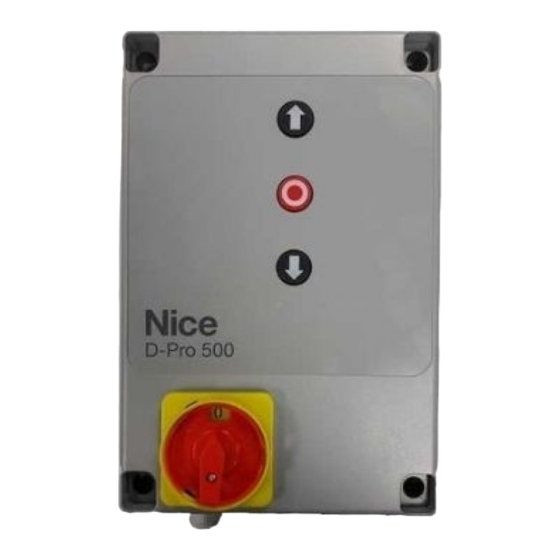
    DPRO500 PRODUKTBESCHREIBUNG UND EINSATZZWECK DEUTSCH Die Steuerungseinheit DPRO500 ist für die Steuerung elektromechanischer Antriebe für Tore, Sektionaltore oder Rollläden bestimmt. ACHTUNG! – Jede andere Verwendung als die hier beschriebene und Aus dem Italienischen übersetzte Anleitung der Gebrauch des Geräts unter abweichenden Umgebungsbedingungen sind als unsachgemäß...
  • Seite 56 4 x 1 mm 5 m (Anmerkung 1) - einphasig 3 x 0,75 mm 2 m (Anmerkung 1) Kabel für MOTOR für Nice Getriebemotoren, Spezialkabel, als Zubehör erhältlich. 5 - 7 - 11 m für andere Marken beim Hersteller des Getriebemotors anfragen Kabel für BLINKLEUCHTE mit Antenne 2 x 1 mm (für Blinkleuchte 230 V AC)
  • Seite 57: Elektrische Anschlüsse

    ING1-photo- (11) - Eingang mit Öffnerkontakt (NC) für Vorrichtungen, die Nehmen Sie nach Befestigung des Gehäuses der Steuerungseinheit und die Bewegung des Antriebs steuern. Wenn dieser Eingang mit der Nice Pro- Anbringung der Öffnung für die Durchführung der Stromkabel (siehe Absatz grammierungseinheit Oview programmiert wird, können die folgenden Be-...
  • Seite 58: Eingang Stop Safety Edge

    3.6 - Eingang STOP SAFETY EDGE • Vergewissern Sie sich, dass die grüne Led L2 (bei den DIP-Schaltern) mit einer Frequenz von einem Blinksignal pro Sekunde gleichmäßig blinkt. Die Funktion des Eingangs SAFETY EDGE besteht darin, ein sofortiges Anhalten des laufenden Bewegungsvorgangs gefolgt von einer kurzen • Wenn in der Anlage Fotozellen vorhanden sind, vergewissern Sie sich, dass Bewegungsumkehr zu bewirken. ihre Led-Anzeigen blinken (RX);...
  • Seite 59: Einlernung Der Öffnungs- Und Schließpositionen Mit Mechanischem Endschalter

    Unterbrechungen durchzuführen. Es ist nicht möglich, die Einlernung Steuerungseinheit verwendet werden; die Programmierungseinheit kann der Sicherheitsvorrichtungen zuerst und die Einlernung der Positionen gleichzeitig an mehrere Steuerungseinheiten (bis zu 16) angeschlossen werden später durchzuführen. und kann auch während des normalen Betriebs des Antriebs angeschlossen bleiben. Bei der Arbeit mit Oview sind unbedingt die Anweisungen in der 3.10.1 - Einlernung der Öffnungs- und Schließpositionen mit mechani- Oview-Bedienungsanleitung zu befolgen.
  • Seite 60: Weiterführende Informationen Und Diagnostik

    Blinken Pausenzeit gelöscht. „OSE“ erkannt Nach den in Tabelle 4 aufgeführten Meldungen zeigt die Steuerungseinheit DPRO500 über die Diagnostik mit Hilfe der Led L2 OK und der Led L1 WARNING eventuelle Fehler an. 6.2 - Diagnostik Einige Geräte sind für das Aussenden von Signalen ausgelegt, über die der Funktionsstatus bzw. etwaige Störungen erfasst werden können. In der folgenden Tabelle werden die unterschiedlichen Signale je nach Problemtyp beschrieben. Die Meldungen erfolgen über die entsprechenden Blinkanzeigen der grünen Led L2 OK und der roten Led L1 WARNING und eventuell über eine Blinkleuchte, die an den Ausgängen der Steuerungseinheit angeschlossen und extra program-...
  • Seite 61: Was Tun, Wenn

    4 Mal Blinken - kurze Pause Fehler Sicherheitsendschalter Das Tor hat die Sicherheitsendschalter beim Öffnen oder beim 4 Mal Blinken - lange Pause Schließen überlaufen. Tor manuell mit Hilfe des Notbedienungssys- tems auf ungefähr halbe Höhe ziehen (siehe Motorhandbuch) und die STOP-Taste auf der Abdeckung drücken, um den Betrieb zu- rückzusetzen. Überlegen Sie, ob die zuvor eingelernten Öffnungs-/ Schließpositionen geändert werden müssen.
  • Seite 62: Entsorgung Des Produkts

    Das nebenstehende Symbol weist darauf hin, dass es verboten ist, dieses Gerät über den Hausmüll zu entsorgen. Es muss entsprechend den örtlichen Bestimmungen entsorgt werden oder dem Verkäufer beim Kauf eines neuen, gleichwertigen Produktes zurückgegeben werden. Achtung! – Die örtlichen Vorschriften sehen für den Fall einer widerrechtlichen Entsorgung dieses Geräts unter Umständen schwere Strafen vor. TECHNISCHE MERKMALE DES PRODUKTS HINWEISE: • Alle technischen Merkmale beziehen sich auf eine Umgebungstemperatur von 20 °C (±5 °C). • Nice S.p.A. behält sich das Recht vor, das Produkt jederzeit nach eigenem Ermessen zu ändern, die Funktionen und den Bestimmungszweck dabei jedoch beizubehalten. Steuerungseinheit für Einphasen- oder Dreiphasenmotoren mit mechanischem oder elektronischem Nice Endschalter Versorgungsspannung Dreiphasig Einphasig 3~400 V AC / 3~230 V AC (+10% - 10%) 50/60 Hz 1~230 V AC (+10% - 10%) 50/60 Hz Max.
  • Seite 63: Eg-Konformitätserklärung

    Erklärung für den Einbau einer „unvollständigen Maschine“ Hinweis - Der Inhalt dieser Erklärung stimmt mit dem offiziell am Geschäftssitz von Nice S.p.A. hinterlegten Dokument überein, insbeson- dere mit der letzten, vor dem Druck dieser Anleitung verfügbaren Revision. Dieser Text wurde aus redaktionellen Gründen angepasst. Eine Kopie der Originalerklärung kann bei Nice S.p.A.
  • Seite 65 OGÓLNE OSTRZEŻENIA: BEZPIECZEŃSTWO - MONTAŻ - UŻYTKOWANIE (instrukcja przetłumaczona z języka włoskiego) Poniższe ostrzeżenia zostały skopiowane bezpośrednio z Przepisów i, jeśli jest to możliwe, należy je stosować do niniejszego produktu UWAGA Ważne instrukcje bezpieczeństwa. Należy przestrzegać wszystkich instrukcji, ponieważ nieprawidłowy montaż może być...
  • Seite 66 • „Dyrektywa Niskonapięciowa”: Szczególne zalecenia związane z możliwością zastosowania produktu do danego użytkowania, w odniesieniu do „Dyrektywy Niskonapięciowej”. Niniejszy produkt spełnia wymagania „Dyrektywy Niskonapięciowej”, jeśli jest wykorzystywany do użytku i w konfigura- cjach przewidzianych w niniejszej instrukcji oraz w połączeniu z artykułami z katalogu produktów firmy Nice S.p.A. Spełnienie wymagań może nie być zagwarantowane, jeśli produkt jest używany w nieprzewidzianych konfiguracjach lub z nieprzewidzianymi, innymi produktami; w takim przypadku zabrania się korzystania z produktu, aż do chwili, gdy instalator sprawdzi zgodność z wymaganiami stawianymi przez dyrektywę. • Dyrektywa „Kompatybilność Elektromagnetyczna”: Szczególną uwagę należy zwrócić na użytkowanie niniejszego produktu w odniesieniu do dyrektywy „Kompatybilność Elektromagnetyczna”. Niniejszy produkt został poddany próbom związanym z kompatybilnością elektromagnetyczną w najbardziej krytycznych warunkach użytko- wania, w konfiguracjach przewidzianych w niniejszej instrukcji oraz w połączeniu z artykułami z katalogu produktów firmy Nice S.p.A. Kompatybilność elektromagnetyczna może nie być zagwarantowana, jeśli produkt jest używany w nieprzewidzianych konfiguracjach lub z nieprzewidzianymi, innymi produktami; w takim przypadku zabrania się korzystania z produktu, aż do momentu, gdy instalator sprawdzi zgodność z wymaganiami stawianymi przez dyrektywę.
  • Seite 67: Spis Treści

    DPRO500 OPIS PRODUKTU I JEGO PRZEZNACZENIE POLSKI Centrala DPRO500 jest przeznaczona do sterowania siłownikami elektrome- chanicznymi do napędu bram, bram segmentowych lub rolet. UWAGA! – Wszelkie inne użycie, różne od opisanego oraz wykorzy- Instrukcja przetłumaczona z języka włoskiego stywanie produktu w warunkach otoczenia odmiennych, niż te, przed- stawione w niniejszej instrukcji jest niezgodne z przeznaczeniem i Spis treści...
  • Seite 68 Typ kabla: Maksymalna dozwolona długość Kabel ZASILAJĄCY CENTRALI STERUJĄCEJ - trójfazowe 4 x 1 mm 5 m (uwaga 1) - jednofazowe 3 x 0,75 mm 2 m (uwaga 1) Kabel SILNIKA do motoreduktorów Nice, odpowiednie kable w 5 - 7 - 11 m sprzedaży jako urządzenia dodatkowe. do różnych marek, złożyć zamówienie u producenta motoreduktora Kabel LAMPY OSTRZEGAWCZEJ z anteną 2 x 1 mm (do lampy ostrzegawczej 230Vac) 10 m kabel ekranowany typu RG58 (do anteny) Kabel FOTOKOMÓREK...
  • Seite 69: Podłączenia Elektryczne

    – Wybór napięcia zasilania: ANTENA - wejście do przyłączenia anteny odbiornika radiowego (uwa- Centrala może funkcjonować prawidłowo z zasilaniem trójfazowym lub jed- ga: antena jest wbudowana w lampy ostrzegawcze Nice LUCY B, MBL, nofazowym (patrz schematy połączeniowe) z napięciami 400V lub 230V. MLBT). Ustawienie domyślne jest dla zasilania trójfazowego 400V. OUT (ZŁĄCZE DO NDA040) - złącze do karty urządzenia dodatkowego Aby wybrać zasilanie jednofazowe 230V, należy działać zgodnie z instrukcję w rozdziale 3.2 NDA040, która posiada dwa wyjścia ze stykami bezpotencjałowymi. Wyjścia...
  • Seite 70: Przyłączenie Odbiornika Radiowego

    dziowe (OSE) lub wyjście ze stałą rezystancją 8,2 kΩ. 3.9 - Całkowite wykasowanie pamięci centrali sterującej Centrala, na etapie wczytywania, identyfikuje rodzaj przyłączonego urządzenia W centrali sterującej można wykasować wszystkie zapisane dane i przywrócić i powoduje „STOP”, gdy dochodzi do jakiejkolwiek zmiany względem rozpo- ją do stanu początkowego z wartościami ustawionymi fabrycznie. znanego stanu. Ustawić przełączniki Za pomocą odpowiednich działań, istnieje możliwość podłączenia do wejścia 1-2-3-4 na ON = zielona STOP SAFETY EDGE więcej niż jednego urządzenia, nawet różnych rodzajów: i czerwona dioda - urządzenia NO: przyłączyć rezystancję 8,2 kΩ równolegle do urządzenia; zacznie szybko migać - urządzenia NC: przyłączyć rezystancję 8,2 kΩ szeregowo do urządzenia; - możliwe jest przyłączenie nieograniczonej liczby urządzeń NC połączonych Przytrzymać wciśnięty 3”...
  • Seite 71: Tryb Funkcjonowania

    Oview można uzyskać dostęp do parametrów nadajników zapisanych w tym Sygnalizacja włączenia Sygnalizacja odbiorniku. Dodatkowe informacje zawarto w instrukcji obsługi programatora Led L2 Led L1 Oview oraz w karcie funkcji centrali, dostępnej również na stronie www.nice- Dioda OK Dioda WARNING foryou.com ZIELONA CZERWONA UWAGA! - Jeśli funkcje z tabeli 3 są zaprogramowane przy użyciu pro- Pusta pamięć (nie wczytano...
  • Seite 72: Diagnostyka

    Po sygnalizacji jak w Tabeli 4, centrala DPRO500 wskazuje ewentualne błędy Ustawienie czasu pauzy zamknięcia automatycznego 1 Ustawić przełącznik typu Dip-Switch 3 i 4 na ON. przy użyciu diagnostyki przy użyciu diod L2 OK i L1 WARNING. 2 Przy użyciu polecenia otwarcia, przenieść bramę na położenie maksymal- 6.1.2 - Inne funkcje nego otwarcia. Kontrolka stanu i diagnostyki (zacisk na klawiaturze) 3 Po osiągnięciu tej pozycji należy odczekać czas równy czasowi pauzy Centrala daje możliwość przyłączenia kontrolki max 24 V – 5 W do zacisku...
  • Seite 73: Co Robić, Jeśli

    8 mignięć - krótka pauza Błąd enkodera Sprawdzić prawidłowe połączenie kabla silnika-centrali, w szczegól- 8 mignięć - długa pauza ności kabla enkodera (6 kolorowych przewodów). Ponownie przepro- wadzić procedurę wczytywania pozycji Otwarcia i Zamknięcia. 9 mignięć - krótka pauza Błąd wczytywania Ponownie powtórzyć procedurę wczytywania pozycji Otwarcia i Za- 9 mignięć - długa pauza ogranicznika krańcowego mknięcia. 10 mignięć - krótka pauza Błąd time-out manewru Wartość domyślna time-out wynosi 60 sekund. Sprawdzić, czy nie 10 mignięć - długa pauza występują zakłócenia w ruchu bramy, czy brama rzeczywiście wy- konała ruch. Sprawdzić (przy użyciu programatora Oview, jeśli jest dostępny), czy został zmieniony czas trwania licznika. Ponownie wy- konać procedurę wczytywania pozycji Otwarcia i Zamknięcia.
  • Seite 74: Utylizacja Produktu

    Ten produkt jest integralną częścią systemu automatyki i w związku z tym należy go usunąć wraz z nim. Tak, jak w przypadku instalacji, również po upływie okresu użytkowania tego produktu czynności demontażowe powinien wykonywać wykwalifikowany personel. Produkt składa się z różnego rodzaju materiałów: niektóre z nich mogą zostać poddane recyklingowi, inne powinny zostać poddane utylizacji. Należy we własnym zakresie zapoznać się z informacjami na temat recyklingu i utylizacji, przewidzianymi w lokalnie obowiązujących przepisach dla danej kategorii produktu. Uwaga! – Niektóre elementy produktu mogą zawierać substancje szkodliwe lub niebezpieczne, które pozostawione w środowisku mogłyby zaszkodzić środo- wisku lub zdrowiu ludzkiemu. Jak wskazuje symbol obok, zabrania się wyrzucania niniejszego produktu razem z odpadami domowymi. W celu usunięcia produktu należy zatem przeprowadzić zgodnie z lokalnie obowiązującymi przepisami „zbiórkę selektywną“ lub zwrócić produkt do sprzedawcy w chwili zakupu nowego, równoważnego produktu. Uwaga! – lokalne przepisy mogą przewidywać poważne sankcje w przypadku samodzielnej likwidacji tego produktu. PARAMETRY TECHNICZNE PRODUKTU OSTRZEŻENIA: • Wszystkie podane parametry techniczne odnoszą się do temperatury otoczenia równej 20°C (± 5°C). • Firma Nice S.p.A. zastrzega sobie prawo do wprowadzania zmian produktu w którejkolwiek chwili, gwarantując jego funkcjonalność i przewidziane zastosowanie. Typologia Centrala sterująca do silników jednofazowych lub trójfazowych z mechanicznym lub elektronicznym ogranicznikiem krańcowym Nice Napięcie zasilania Trójfazowe Jednofazowe 3~400Vac / 3~230Vac (+10% - 10%) 50/60Hz 1~230Vac (+10% - 10%) 50/60Hz Moc max silnika...
  • Seite 75: Deklaracja Zgodności We

    Uwaga - Treść niniejszej deklaracji zgodności odpowiada oświadczeniom znajdującym się w oficjalnym dokumencie złożonym w siedzibie firmy Nice S.p.A., a w szczególności jego ostatniej wersji dostępnej przed wydrukowaniem niniejszej instrukcji. Niniejszy tekst został dosto- sowany w celach wydawniczych. Kopię oryginalnej deklaracji można uzyskać w siedzibie spółki Nice S.p.A. (TV) Italy.
  • Seite 77 ALGEMENE WAARSCHUWINGEN: VEILIGHEID - INSTALLATIE - GEBRUIK (instructies, vertaald uit het Italiaans) De hierop volgende aanbevelingen zijn direct overgenomen uit de Normen en kunnen, voor zover mogelijk, worden toegepast op het beschreven product LET OP Belangrijke aanwijzingen voor de veiligheid. Volg alle voorschriften op, want een niet-correct uitgevoerde installatie kan ernstige schade veroorzaken LET OP Belangrijke aanwijzingen voor de veiligheid.
  • Seite 78 Bijzondere waarschuwingen betreffende de geschiktheid voor het gebruik van het product met betrekking tot de Laagspanningsrichtlijn. Dit product voldoet aan de eisen van de Laagspanningsrichtlijn als het wordt aangewend voor het gebruik en de configuraties beschreven in deze instructiehandleiding en in combinatie met de artikelen uit de productencatalogus van Nice S.p.A. De conformiteit aan de eisen kan mogelijk niet gegarandeerd worden als het product wordt gebruikt in configuraties of met andere niet voorziene producten. Het is verboden om het product in deze situaties te gebruiken tot degene die de installatie uitvoert heeft gecontroleerd of aan de eisen van de richtlijn is voldaan.
  • Seite 79: Beschrijving Van Het Product En Gebruiksbestemming

    DPRO500 BESCHRIJVING VAN HET PRODUCT EN GEBRUIKSBESTEMMING NEDERLANDS De besturingseenheid DPRO500 is bestemd voor het bedienen van elektrome- chanische actuatoren voor de automatisering van hekken, sectionaalpoorten of rolluiken. Instructies, vertaald uit het Italiaans LET OP! – Elk ander gebruik dan in deze handleiding is beschreven of...
  • Seite 80 - driefasig 4 x 1 mm 5 m (opmerking 1) - eenfasig 3 x 0,75 mm 2 m (opmerking 1) MOTORKABEL voor Nice reductiemotoren zijn speciale kabels 5 - 7 - 11 m verkrijgbaar als accessoire. voor reductiemotoren van andere merken dient u contact op te nemen met de motorfabrikant Kabel KNIPPERLICHT met antenne 2 x 1 mm...
  • Seite 81: Elektrische Aansluitingen

    – Halt bij sluiting Voor instructies voor de programmering en de beschrijving van de beschikbare - Motor met mechanische eindaanslag (afb. 7) functies dient u de functiekaarten van Oview voor DPRO500 te raadplegen. Sluit tenslotte de elektriciteitskabels van de verschillende inrichtingen ALT - ingang voor inrichtingen die de lopende beweging stoppen. Sluit con- aan, aan de hand van de afb.
  • Seite 82: Ingang Stop Safety Edge

    3.6 - Ingang STOP SAFETY EDGE • Controleer of de rode SAFETY-led dichtbij de connector van de kabel van het toetsenbord permanent brandt (zie de diagnostiektabel Led Safety in paragraaf 6.2). De functie van de ingang SAFETY EDGE is het veroorzaken van het direct Als ook maar een van deze controles niet het gewenste resultaat heeft, moet stoppen van de momentane beweging na een korte omkering.
  • Seite 83: Werkwijze

    (max. 16) worden aangesloten en kan ook tijdens de normale werking van de 6.1.1 - Signaleringen bij het inschakelen automatisering aangesloten blijven. Teneinde Oview te gebruiken, is het heel Bij het inschakelen van de besturingseenheid DPRO500 is de reactie van de leds belangrijk dat u de aanbevelingen in de instructiehandleiding van Oview in acht L2 OK (groen) en L1 WARNING (rood) van groot belang, zoals beschreven in neemt.
  • Seite 84: Andere Functies

    3 Zodra deze stand is bereikt, wacht u net zo lang als de pauzetijd van de Na de signaleringen van Tabel 4 zal de besturingseenheid DPRO500 eventueel gewenste automatische sluiting en geeft u een sluitingsinstructie. De pauze- enkele storingen tonen, d.m.v. de diagnostiek die wordt verkregen door de leds tijd van de automatische sluiting is nu opgeslagen.
  • Seite 85 7 keer knipperen - korte pauze Storing communicatie RS485 Controleer de juiste aansluiting van de kabel tussen de motor en 7 keer knipperen - lange pauze Encoder de besturingseenheid, in het bijzonder die van de encoderkabel (6 gekleurde draden). 8 keer knipperen - korte pauze Storing encoder Controleer de juiste aansluiting van de kabel tussen de motor en 8 keer knipperen - lange pauze de besturingseenheid, in het bijzonder die van de encoderkabel (6 gekleurde draden).
  • Seite 86: Wat Te Doen Als

    WAT TE DOEN ALS... (handleiding voor het oplossen van problemen) Hieronder volgen de eventuele storingen die zich kunnen voordoen tijdens de installatie of in geval van een defect, en de mogelijke oplossingen: • De motor staat stil, er wordt geen instructie voor beweging gegeven en de rode led knippert: controleer het soort knipperingen aan de hand van de diagnostiektabel led L1 warning (par. 6.2) en druk op de rode STOP-knop om de diagnostiek te wissen. • De RF-zender geeft de instructie voor beweging niet en de led op de zender gaat niet branden: controleer of de batterijen van de zender leeg zijn en vervang ze indien nodig.
  • Seite 87: Waarschuwingen

    TECHNISCHE SPECIFICATIES VAN HET PRODUCT WAARSCHUWINGEN: • Alle vermelde technische gegevens hebben betrekking op een omgevingstemperatuur van 20°C (± 5°C). • Nice S.p.A. behoudt zich het recht voor om, op elk moment dat dit noodzakelijk wordt geacht, wijzigingen aan het product aan te brengen, waarbij hoe dan ook de gebruiksbestemming en de functionaliteit ervan gelijk blijven. Type Besturingseenheid voor eenfase- of driefasenmotoren met mechanische of elektronische eindaanslag van Nice Voedingsspanning Driefasig Eenfasig 3~400Vac / 3~230Vac (+10% - 10%) 50/60Hz 1~230Vac (+10% - 10%) 50/60Hz Max. vermogen motor 2.2kW Vermogen in stand-by < 5W Zekering vermogensprintplaat F1: 500 mA Type F; F2,F3,F4: 6.3A Type T Uitgang 1 (met NDA040)
  • Seite 88 NB – de inhoud van deze verklaring stemt overeen met hetgeen verklaard is in het officiële document dat gedeponeerd is bij de vestiging van Nice S.p.A., en in het bijzonder met de laatste revisie hiervan die vóór het afdrukken van deze handleiding beschikbaar was. Onderstaande tekst is om redactionele redenen aangepast.
  • Seite 89: Меры Предосторожности При Монтаже

    пламени. Все вышеописанные действия могут привести к выходу изделия из строя или возникновению опасных ситуаций. Если такое произойдет, немедленно прекратите монтаж и обратитесь в отдел технической поддержки компании Nice • Изготовитель не несет никакой ответственности за ущерб, причиненный имуществу или здоровью людей вследствие...
  • Seite 90 Данное изделие успешно прошло испытания на электромагнитную совместимость в наиболее критических условиях эксплу- атации в конфигурациях, описанных в настоящем руководстве, и в сочетании с устройствами, приведенными в каталоге про- дукции компании Nice S.p.A. Электромагнитная совместимость не может быть гарантирована при использовании изделия в конфигурациях или с устрой- ствами, не...
  • Seite 91: Описание И Назначение Изделия

    DPRO500 ОПИСАНИЕ И НАЗНАЧЕНИЕ ИЗДЕЛИЯ РУССКИЙ Блок DPRO500 предназначен для управления электромеханическими исполнительными механизмами для автоматизации ворот, секционных дверей или жалюзи. Оригинальное руководство: итальянский язык ВНИМАНИЕ! – Любое использование, отличное от вышеуказанного, и в условиях, отличных от приведенных в настоящем руководстве, Содержание...
  • Seite 92 Кабель запираемого на ключ ПЕРЕКЛЮЧАТЕЛЯ 2 кабеля 2 х 0,25 мм 10 м (прим. 2) Кабель СПИРАЛЬНЫЙ для чувствительной кромки Спиральный кабель Nice доступен для заказа как 50 м дополнительная принадлежность. Примечание 1. Если длина кабеля питания превышает максимально допустимые величины длины, следует использовать кабель с большим сечением.
  • Seite 93: Электрические Соединения

    сти за возможный ущерб, вызванный ненад- ENCODER - вход для подключения кабеля электронного концевого лежащим использованием отдельных компо- датчика (энкодера Nice). Не может использоваться в этой версии. нентов системы и несоблюдением указаний, COMMON (8) - вход с 24 В постоянного тока, который является общим...
  • Seite 94: Подсоединение Радиоприемника

    3.8 - Первое включение и проверка подключений Наконец, подключите электрические кабели остальных После подачи напряжения на блок управления выполните следующие установленных устройств (см. Рис. A и пар. 3.3). проверки: Примечание. Для облегчения подключения кабелей блоки контактных • Удостоверьтесь, что зеленый светодиод L2 (рядом с DIP- зажимов...
  • Seite 95: Запоминание Положений Открытия И Закрытия С Механическим Концевым Датчиком

    Эту процедуру необходимо повторить в случае модификации ВЫКЛ ВКЛ ВКЛ Автоматический режим с задаваемым устройств, подключенных к клемме «STOP Safety Edge» (напри- (ON) (ON) временем паузы, если положения внесе- мер, после подключения нового устройства к блоку управления). ны в память (для запоминания времени После...
  • Seite 96: Подробная Информация И Диагностика

    вспышки безопасности «OSE» рас- 2 секунд познано После сигналов, как указано в Таблице 4, блок управления DPRO500 демонстрирует возможные ошибки посредством диагностики, прово- димой с помощью светодиодов L2 OK и L1 WARNING. 6.2 - Диагностика Некоторые устройства могут подавать сигналы, по которым можно распознать рабочее состояние или же возможные неполадки. В следую- щей...
  • Seite 97 ДИАГНОСТИКА КРАСНОГО СВЕТОДИОДА L1 WARNING Некоторые сигналы оповещения могут быть удалены нажатием красной кнопки STOP Оповещение Причина Способ устранения Мигающее устройство 5 вспышек - короткая пауза Ошибка ЭСППЗУ - Выключите и включите блок управления. Если ошибка не исчезнет, вы- Вспышка 5 вспышек...
  • Seite 98: Что Делать, Если

    ЧТО ДЕЛАТЬ, ЕСЛИ... (руководство по поиску и устранению неисправностей) Далее приведены возможные неполадки, которые могут обнаружиться при монтаже или в случае ошибки и возможные способы устранения: • Двигатель остановлен, нет команды ни для каких операций, красный светодиод мигает: проверьте тип последовательности вспышек, сверившись...
  • Seite 99: Технические Характеристики Изделия

    ТЕХНИЧЕСКИЕ ХАРАКТЕРИСТИКИ ИЗДЕЛИЯ ПРЕДУПРЕЖДЕНИЯ: • Все технические характеристики приведены для температуры 20°C (± 5°C). • Компания Nice S.p.A. сохраняет за собой право внесения изменений в настоящее руководство и конструкцию изделия, с сохранением функциональности и предназначения последнего, в любой момент без предварительного уведомления заказчиков.
  • Seite 100: Декларация Соответствия Ес

    Примечание. Содержание настоящей декларации соответствует данным, задекларированным в официальном документе, который может быть представлен в офисе компании Nice S.p.A., и в частности, в его последней версии, доступной до момента передачи настоящего руководства в печать. Приведенный текст декларации был адаптирован по издательским соображениям. Копию...
  • Seite 104 Nice S.p.A. Via Pezza Alta, 13 31046 Oderzo TV Italy www.niceforyou.com info@niceforyou.com...

Inhaltsverzeichnis