Siko GP43 Originalmontageanleitung
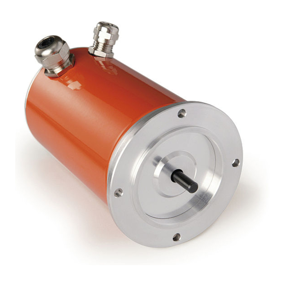
Getriebepotentiometer mit endschalter
Vorschau ausblenden
Andere Handbücher für GP43:
- Benutzerinformation (12 Seiten) ,
- Benutzerinformation (12 Seiten)

Verwandte Anleitungen für Siko GP43


Inhaltszusammenfassung für Siko GP43
- Seite 1 GP43, GP44 Getriebepotentiometer mit Endschalter Deutsch Originalmontageanleitung Seite 2 Geared potentiometer with Limit Switches English Translation of the Original Installation Instructions page 24 GP43 GP44 375/17...
-
Seite 2: Inhaltsverzeichnis
5.6 Abgleich des Messwandlers MWU mit elektronischen Schaltausgängen (GP43-SP03) 5.7 Was tun wenn... 6 Inbetriebnahme 7 Transport, Lagerung, Wartung und Entsorgung 8 Zubehör Anschluss-Stecker 8.1 Gegenstecker M12 gerade 9 Technische Daten GP43, GP44 · Datum 23.05.2018 · Art. Nr. 79804 · Änd. Stand 375/17... -
Seite 3: Dokumentation
3. Die vorgeschriebenen Betriebs- und Installationsbedingungen sind einzuhalten. 4. Der Getriebepotentiometer darf nur innerhalb der technischen Daten und der angegebenen Grenzen betrieben werden (siehe Kapitel 9). GP43, GP44 · Datum 23.05.2018 · Art. Nr. 79804 · Änd. Stand 375/17... -
Seite 4: Kennzeichnung Von Gefahren Und Hinweisen
` Projektierung, Inbetriebnahme, Montage und Wartung nur durch geschultes Fachpersonal. ` Dieses Personal muss in der Lage sein, Gefahren, welche durch die mechanische, elektrische oder elektronische Ausrüstung verursacht werden können, zu erkennen. GP43, GP44 · Datum 23.05.2018 · Art. Nr. 79804 · Änd. Stand 375/17... -
Seite 5: Grundlegende Sicherheitshinweise
Unsachgemäße Montage (z. B. Spannungen an der Antriebswelle) führt zu zusätzlicher Erwärmung und langfristig zur Zerstörung des Getriebepoten- tiometers. ` Sorgen Sie für einen geringen Wellen- und Winkelversatz zwischen Welle und Aufnahmebohrung durch geeignete Fertigungsmaßnahmen. GP43, GP44 · Datum 23.05.2018 · Art. Nr. 79804 · Änd. Stand 375/17... -
Seite 6: Elektrische Installation
Das System in möglichst großem Abstand von Leitungen ein- bauen, die mit Störungen belastet sind. Gegebenenfalls sind zusätzliche Maßnahmen, wie Schirmbleche oder metallisierte Gehäuse vorzusehen. GP43, GP44 · Datum 23.05.2018 · Art. Nr. 79804 · Änd. Stand 375/17... - Seite 7 • Prüfen Sie, ob der O-Ring korrekt in der Nut liegt. • Setzen Sie die Gehäusehaube/Rückwand auf den Flansch auf. Beach- ten Sie dabei, dass der O-Ring nicht beschädigt wird. • Ziehen Sie die Befestigungsschrauben fest an. GP43, GP44 · Datum 23.05.2018 · Art. Nr. 79804 · Änd. Stand 375/17...
-
Seite 8: Kabelanschluss
Verschraubung einpassen. • Die Mutter aufschrauben und die komplette Verschraubung (mit O-Ring zur Abdichtung) an der Haube anbringen. Abb. 3: Kabelanschluss PG7 GP43, GP44 · Datum 23.05.2018 · Art. Nr. 79804 · Änd. Stand 375/17... - Seite 9 • Schließen Sie das Gerät (siehe Kapitel 4.2). Anschlussbelegung ohne Messwandler Klemme Drehrichtung e Drehrichtung i Schaltnocke A Schaltnocke B Schaltnocke C Potentiometer Abb. 5: Anschlussbelegung ohne Messwandler GP43, GP44 · Datum 23.05.2018 · Art. Nr. 79804 · Änd. Stand 375/17...
- Seite 10 Abb. 7: Anschlussbelegung mit Messwandler Abb. 8: Anschluss Bürde gegen Masse Abb. 9: Anschluss Bürde gegen +UB GP43, GP44 · Datum 23.05.2018 · Art. Nr. 79804 · Änd. Stand 375/17...
-
Seite 11: Anschlussbelegung Spezifikation Gp43-Sp01
• 4 pol. Stiftkontakt M12 A-kodiert (Potentiometer). Zubehör Gegenstecker siehe Kapitel 8. Belegung Ansichtseite = Steckseite Abb. 11: Anschluss SP02 (Potentiometer) GP43, GP44 · Datum 23.05.2018 · Art. Nr. 79804 · Änd. Stand 375/17... -
Seite 12: Anschlussbelegung Spezifikation Gp43-Sp03
4.7 PE-Anschluss GP44 Nach Öffnen des Gerätes (siehe Kapitel 4.2) muss zusätzlich bei >48 V (gemäß Niederspannungsrichtlinie), mit einer M4 Schraube (Gewinde- tiefe 10 mm), ein Schutzleiter angeschlossen werden. GP43, GP44 · Datum 23.05.2018 · Art. Nr. 79804 · Änd. Stand 375/17... -
Seite 13: Einstellung Und Abgleich
Bei Drehrichtung "e" und voll auf Endanschlag in Richtung "i" gedrehter Welle ist der Potentiometerwert am Schleifer S zwischen dem Potentiome- teranfang Po gleich 0 Ohm. Wenn die Welle in Richtung "e" gedreht wird, steigt der Widerstandswert. GP43, GP44 · Datum 23.05.2018 · Art. Nr. 79804 · Änd. Stand 375/17... -
Seite 14: Einrichtung Potentiometer
Schraubendreher Größe 3 (siehe Abb. 15). Schaltnocke A Schaltnocke B Schaltnocke C Gewindestift Feineinstellschraube Innensechskant 1.5 Schraubendreher 3 Abb. 15: Einstellung der Schaltnocken GP43, GP44 · Datum 23.05.2018 · Art. Nr. 79804 · Änd. Stand 375/17... -
Seite 15: Abgleich Des Messwandlers Mwi
7) drehen, bis Endwert (20 mA) 4. Potentiometer (Pe) (siehe gemessen wird. Die Schritte 1 ... 4 sind solange zu wiederholen, bis die Werte austariert sind (iterativer Abgleich). GP43, GP44 · Datum 23.05.2018 · Art. Nr. 79804 · Änd. Stand 375/17... -
Seite 16: Abgleich Des Messwandlers Mwu (Gp43-Sp01)
Abb. 18: Einstellen des Trimmpotentiometers Einstellbarkeit: • Mit Trimmpotentiometer Pe kann die Spannung von 10 V bei Potentio- meterwerten von 60 ... 100 % des Gesamtwertes eingestellt werden. GP43, GP44 · Datum 23.05.2018 · Art. Nr. 79804 · Änd. Stand 375/17... -
Seite 17: Abgleich Des Messwandlers Mwu Mit Elektronischen Schaltausgängen (Gp43-Sp03)
Endstellung der Anwendung angepasst werden. Trimmpotentiometer VER Verstärker für Ausgangs- spannung Trimmpotentiometer OGW Oberer Grenzwert Einstel- lung Trimmpotentiometer UGW UntererGrenzwert Einstel- lung Abb. 19: Einstellen des Trimmpotentiometers GP43, GP44 · Datum 23.05.2018 · Art. Nr. 79804 · Änd. Stand 375/17... -
Seite 18: Was Tun Wenn
• Prüfen Sie, ob Sie mit dem kleineren Strombereich auskommen kön- nen, andernfalls müssen Sie die Übersetzung des Getriebes entspre- chen anpassen (durch Bestellung/Änderung einer anderen Überset- zung bei SIKO). GP43, GP44 · Datum 23.05.2018 · Art. Nr. 79804 · Änd. Stand 375/17... -
Seite 19: Inbetriebnahme
Staub, Hitze und Feuchtigkeit schützen. • Anschlüsse weder durch mechanische noch durch thermische Einflüsse beschädigen. • Vor Montage ist der Getriebepotentiometer auf Transportschäden zu untersuchen. Beschädigte Getriebepotentiometer nicht einbauen. GP43, GP44 · Datum 23.05.2018 · Art. Nr. 79804 · Änd. Stand 375/17... -
Seite 20: Zubehör Anschluss-Stecker
über Kabelmantel schieben. 2. Kabel abmanteln, Leiter abisolieren und verzinnen. oder 4.5). 3. Litzen in Einsatz schrauben (entsprechend Kapitel 4. Teile montieren. 5. Druckschraube mit Kupplungshülse verschrauben. GP43, GP44 · Datum 23.05.2018 · Art. Nr. 79804 · Änd. Stand 375/17... -
Seite 21: Technische Daten
Lebensdauer Potentio- 1x 10 Umdrehung(en) meter Elektrische Daten GP43, GP44 Geber Potentiometer Typ 01, 1 Wendel Ergänzung Belastbarkeit 1 W bei 70 °C ≤30 V Widerstand 1, 5, 10 kΩ GP43, GP44 · Datum 23.05.2018 · Art. Nr. 79804 · Änd. Stand 375/17... - Seite 22 Messwandler, Stromausgang Ergänzung Betriebsspannung 24 V DC ±20 % Ausgangsstrom 4 … 20 mA bei Bürde ≤500 Ω Messwandler, Spannungsausgang Ergänzung (nur Spezifikation GP43-SP01+SP03) Betriebsspannung 24 V DC ±20 % Ausgangsspannung 0 … 10 V ≤10 mA Last GP43, GP44 · Datum 23.05.2018 · Art. Nr. 79804 · Änd. Stand 375/17...
- Seite 23 -20 … 80 °C -20 … 85 °C bei GP43-SP03 relative Luftfeuchtigkeit Betauung nicht zulässig EN 61000-6-2 Störfestigkeit / Immission EN 61000-6-4 Störaussendung / Emission Schutzart IP52 EN 60529 GP43, GP44 · Datum 23.05.2018 · Art. Nr. 79804 · Änd. Stand 375/17...
- Seite 46 GP43, GP44...
- Seite 47 GP43, GP44...
- Seite 48 SIKO GmbH Weihermattenweg 2 79256 Buchenbach Telefon/Phone + 49 7661 394-0 Telefax/Fax + 49 7661 394-388 E-Mail info@siko.de Internet www.siko-global.com Service support@siko.de...