Herunterladen Inhalt Inhalt Diese Seite drucken

Werbung

Verfügbare Sprachen
  • DE

Verfügbare Sprachen

  • DEUTSCH, seite 1
S-Plasma
50 / 60P / 80P / 120
BEDIENUNGSANLEITUNG
User manual | Manuel d´utilisation | Istruzioni per l'uso | Manual de instrucciones

Werbung

Inhaltsverzeichnis
loading

Inhaltszusammenfassung für STAMOS S-Plasma 50

  • Seite 1 S-Plasma 50 / 60P / 80P / 120 BEDIENUNGSANLEITUNG User manual | Manuel d´utilisation | Istruzioni per l‘uso | Manual de instrucciones...
  • Seite 2 INHALT | CONTENU | CONTENT | CONTENUTO | CONTENIDO | TREŚĆ Diese Bedienungsanleitung beinhaltet Beschreibungen, Bedienungsanleitungen und grundsätzliche Wartungsvorgänge für die Stamos Germany Plasmaschneider S-Plasma 50/60/120/160. Studieren Sie diese Bedienungsanleitung ausführlich. Ein vollständiges Verständnis der Eigenschaften und der Einsatzmöglichkeiten des Gerätes gewährleistet Deutsch die sachgemäße Anwendung.
  • Seite 3: Elektrischer Schock Ist Lebensgefährlich

    SCHNEIDEN SIE NICHT AN GESCHLOSSENEN BEHÄLTERN WIE Isolierungsmatten oder Abdeckungsplanen benutzen, die groß genug sind um Z.B. TANKS ODER FÄSSERN jegliche körperliche Kontakte mit der Arbeit oder dem Boden zu vermeiden. • Berühren Sie keine Teile der Fackel, wenn diese gerade in Kontakt mit dem Verbinden Sie die Arbeitskabel, so praktisch wie möglich, mit einer in der Nähe des Gegenstand oder dem Boden ist.
  • Seite 4 • Benutzen Sie Schutzblenden oder Abtrennungen um andere vor blendendem Eine SIGNIFIKANTE GLEICHSPANNUNG besteht nach dem Entfer- Licht oder Funken zu schützen; Warnen Sie andere davor in den Lichtbogen nen des Stromkabels in der Stromquelle zu schauen. Tragen Sie Schutzkleidung die mit widerstandsfähigem, feuer- sicherem Material (Leder, schwere Baumwolle oder Wolle) hergestellt wurde Schalten Sie das Gerät aus, trennen Sie das Stromkabel, überprüfen Sie die und geeignete Arbeitsschuhe.
  • Seite 5: Duty Cycle

    b) Wenn das Schneidgerät die standardmäßige Belastungsdauer WÄRMESCHUTZ überschreitet, setzt der Schutzmodus ein und die Maschine stellt ihre Funktion ein. Das heißt, dass das Gerät jetzt ausläuft Der Wärmeschutzkreislauf setzt sich in Gang, wenn das Gerät die Einschaltdauer um die Temperaturkontrolle wieder herstellen zu können, nachdem überschreitet.
  • Seite 6: Anschlussschema S-Plasma

    Schale des Schweißgerätes mittels eines Kabels, dessen Einschnitt nicht kleiner sein darf als 6mm, mit der Erde zu verbinden, um potentiellen Problemen durch Entweichung von Elektrizität vorzubeugen. INFORMATIONEN ZU S-PLASMA 50 ZUSÄTZLICHER STROMANSCHLUSS FÜR DEN PLASMABRENNER SCHLAUCH...
  • Seite 7: Zubehör S-Plasma

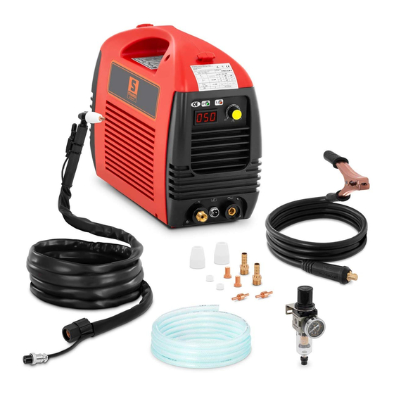
    (schwarze Kabel) können beliebig an L1, L2 und L3 angeschlossen werden (bitte nur von einer Elektrofachkraft ausführen lassen). NORMALSTROM: Das Gerät arbeitet mit einem 1-Phasenanschluss (230V +/- 10%). 1 PH ZUBEHÖR S-PLASMA 50 1. Tasche 2. Verschleißteile 3. Druckminderer + Manometer 4. Masseklemme 5. Luftschlauch...
  • Seite 8: Zubehör Zu S-Plasma 60P/ 80P

    INFORMATIONEN ZU S-PLASMA 60P / 80P ZUBEHÖR ZU S-PLASMA 60P/ 80P MOSFET: MOSFeT In diesem Inverter kommt die MOS-FET Technologie zu 1. Masseklemme tragen. Diese Technologie schafft es wie keine andere, eine 2. Luftschlauch maximale Ergiebigkeit zu erreichen. 3. Tasche Im Vergleich zur verwendeten Strommenge erhält man eine 4.
  • Seite 9: Zubehör Zu S-Plasma 120

    INFORMATIONEN ZU S-PLASMA 120 ZUBEHÖR ZU S-PLASMA 120 1. Druckminderer + Manometer 2. Luftschlauch 3. Masseklemme 4. Plasmabrenner IGbT IGBT: Ein Bipolartransistor mit isolierter Gate-Elektrode (english Insulated Gate Bipolar Transistor, kurz IGBT) ist ein Halbleiterbauelement, das zunehmend in der Leistungselektronik verwendet wird, da es Vorteile des Bipolartransistors (z.B.
  • Seite 10: Technische Details

    Sichern Sie die Konstruktion noch einmal durch leichtes Gewicht (netto) 9 kg 19 kg 20 kg 36 kg Festziehen mit einem Schraubenschlüssel. Ziehen Sie es nicht zu straff zu. Abmessung L/H/B (mm) 380x290x160 490x210x370 495x215x375 500x370x350 PISTOLENAUFBAU (S-Plasma 50/ 60P/ 80P)
  • Seite 11: Wartung

    A. Vorgang des Pistolenlaufbaus dafür sind Funken, die von der Oberseite des Arbeitsgegenstandes absprühen. Bewegen Stellen Sie die Pistole mit der Schutzkappe nach oben zeigend auf, und drehen Sie die Pistole gerade so schnell, dass die Funkenansammlung an der Unterseite des Sie die Schutzkappe, von der Pistole ab.
  • Seite 12 SAVE THIS MANUAL Keep this manual for the safety warnings and precautions, assembly, operating, in- spection, maintenance and cleaning procedures. Write the product’s serial number in the back of the manual near the assembly diagram (or month and year of purchase if product has no number).
  • Seite 13: Electrical Safety

    2. Do not operate power tools in explosive atmospheres, such as in PERSONAL SAFETY the presence of flammable liquids, gases, or dust. Power tools create 1. Stay alert. Watch what you are doing, and use common sense sparks which may ignite the dust or fumes. when operating a power tool.
  • Seite 14: Specific Safety Rules

    6. Maintain tools with care. Keep cutting tools maintained and clean. 7. Prevent eye injury and burns. Wearing and using the approved personal Properly maintained tools are less likely to bind and are easier to control. Do not safety clothing and safety devices reduce the risk for injury. use a damaged tool.
  • Seite 15 h. Dangerously reactive or flammable gases, vapors, liquids, and dust. • Follow OSHA guidelines for Permissible Exposure Limits (PEL’s) for various i. Provide adequate ventilation in work areas to prevent accumulation of fumes and gases. flammable gases, vapors, and dust. Do not apply heat to a container that •...
  • Seite 16 DUTY CYCLE POWER INDICATOR: This indicator lights up after turning the machine The duty cycle is the percentage of the operating time (measured in minutes) of a 10-minute period in which the machine is used continuously in normal temperature conditions. If the values of the duty cycle are exceeded, this will trigger the overheat protection function, which stops the machine until it is cooled down to normal opera- ting temperature.
  • Seite 17 6 mm diameter, in order to prevent potential problems caused by electricity leakages. ADDITIONAL POWER CONNECTION FOR THE PLASMA TORCH HOSE S-PLASMA 50 CONNECTION DIAGRAM MOSFET: MOSFeT This inverter uses MOS-FET technology. More than any other technology, the MOS-FET enables the achievement of maximum effectiveness.
  • Seite 18 ACCESSORIES S-PLASMA 60P / 80P Parts subject to wear Pressure regulator + manometer Grounding clamp cable Air hose Plasma torch POWER SUPPLY FOR S-PLASMA 60P /80P /120 HIGH POWER: These devices use a 3-phase connection (380V +/- 10%). 3 PH MOSFET: MOSFeT The yellow-green wire is used as a PE protective wire connector.
  • Seite 19 S-PLASMA 120 ACCESSORIES IGbT IGBT: 1. Grounding clamp cable A bipolar transistor with insulated gate electrode (insulated 2. Air hose gate bipolar transistor, IGBT) is a semiconductor that 3. Bag is increasingly used in power electronics, as the bipolar 4. Plasma torch transistors offer certain advantages (e.g.
  • Seite 20: Technical Details

    ACCESSORIES TECHNICAL DETAILS S-Plasma 50 S-Plasma 60P S-Plasma 80P S-Plasma 120 Input voltage 230V 1-phase 400V 3-phase 400V 3-phase 400V 3-phase Frequency 50/60 Hz 50/60 Hz 50/60 Hz 50/60 Hz Input current Open circuit voltage 116V 200V 240V Degree of protection of the...
  • Seite 21 Hold the tip of the pistol above the workpiece, press the pistol switch and move the pi- stol tip until it comes into contact with the workpiece and the cutting arc is established. PISTOL ASSEMBLY (S-Plasma 50/60P/80P) Once the cutting arc is generated you may move the pistol in the desired direction with the tip of the pistol always at a slight angle and maintaining contact with the workpiece.
  • Seite 22: Maintenance

    2. Weekly activities Verify the proper operation of the air flow. Blow off or suck in dust or dirt from the entire machine, including the air filter. 3. Distance cutting In some cases it may be advantageous to perform cutting with the tip of the pistol at a height of approximately 1/16“...
  • Seite 23: Informations De Securite Importantes

    CONSERVEZ CE MANUEL N’utilisez pas d’appareil électrique dans des atmosphères explosives, en Conservez ce manuel pour les instructions de sécurité, les précautions d’emploi, présence de liquides, gaz ou poussières inflammables par exemple. Les ap l’assemblage, le fonctionnement, l’inspection, la maintenance et les procédures pareils électriques font des étincelles risquant d’enflammer les poussières ou d’entretien.
  • Seite 24: Sécurité Personnelle

    Si vous utilisez un appareil électrique à l’extérieur, utilisez une rallonge Débranchez l’appareil de la source d’alimentation avant de faire un quelcon marquée « W-A » ou « W ». Ce type de rallonge est adapté à un usage à que ajustement, de changer d’accessoire, ou d’entreposer l’appareil.
  • Seite 25 Maintenez un environnement de travail sûr. Votre espace de travail doit re Enveloppez l’aire de travail avec des écrans résistant au feu portables. Proté ster bien éclairé et avoir suffisamment d’espace pour pouvoir circuler. Veillez gez les murs, plafonds, sols combustibles des étincelles et de la chaleur avec à...
  • Seite 26 WARNING Mettez les bonbonnes à l’abri. Mettez les bonbonnes près d’un mur, sur un DANGER D’INHALATION : LA SOUDURE ET LE DÉCOUPE PAR chariot ou autre afin de les empêcher de tomber. Toute bonbonne doit être PLASMA PRODUIT DES FUMÉES TOXIQUES. utilisée et entreposée à...
  • Seite 27: Facteur De Marche

    b) Lorsque l‘appareil dépasse la limite du facteur de marche, le mode FACTEUR DE MARCHE de protection s‘active et la machine s‘arrête. C‘est-à-dire que l‘appareil Le facteur de marche est le rapport exprimé en pourcentage du temps de fonctionne- n‘est plus en marche afin de rétablir le contrôle de la température ment continu de l’appareil (mesuré...
  • Seite 28 SCHÉMA DES RACCORDEMENTS S-PLASMA 50 GAZ/RACCORDEMENT POUR L’AIR cordon d’alimentation compresseur d’air réducteur de pression isolation de l’armature PRISE DE TERRE: câble de masse Derrière chaque machine à souder se trouvent une vis et un marquage pièce à travailler pour atteindre la prise de terre indispensable. Avant l’utilisation, il brûleur plasma...
  • Seite 29 BRANCHEMENT SUR LE RÉSEAU POUR S-PLASMA 60/80/120 MOSFET: MOSFeT La technologie MOSFET (transistor à effet de champ à structure métal-oxyde-semi-conducteur) s’applique à cet COURANT FORT: onduleur. Comparé à la quantité de courant utilisé, on L’appareil fonctionne avec un raccordement triphasé (380V obtient ainsi une performance démesurée.
  • Seite 30 S-PLASMA 60P / 80P ACCESSOIRES MOSFET: MOSFeT La technologie MOSFET (transistor à effet de champ à 1. Pince de masse crocodile structure métal-oxyde-semi-conducteur) s’applique à cet 2. Tube à air onduleur. Comparé à la quantité de courant utilisé, on 3. Sac obtient ainsi une performance démesurée.
  • Seite 31 S-PLASMA 120 ACCESSOIRES 1. Régulateur de pression + manomètre 2. Tube à air 3. Pince de masse crocodile 4. Torche plasma IGbT IGBT: Le transistor bipolaire à grille isolée (de l’anglais Insulated Gate Bipolar Transistor, abrégé IGBT) est un dispositif semi- conducteur, qui est de plus en plus utilisé...
  • Seite 32: Détails Techniques

    à ne pas trop serrer. Conformité aux directives européennes Poids (net) 9 kg 19 kg 20 kg 36 kg ASSEMBLAGE DE LA TORCHE (S-Plasma 50/ 60/ 80) Dimensions L/h/l (mm) 380x290x160 490x210x370 495x215x375 500x370x350 Électrode – Diffuseur – Tuyère – Buse standard...
  • Seite 33 A. Assembler la torche Assurez-vous que le matériel est bien coupé avant d’aller plus loin dans la découpe. Inclinez la torche avec sa buse protectrice vers le haut et dévissez la buse protec- Réglez la vitesse comme recommandé. trice du pistolet. (La buse protectrice maintient la tuyère, le diffuseur en céramique et l’électrode.) Enlevez la buse, le diffuseur en céramique et l’électrode.
  • Seite 34: Instrukcja Obsługi

    Niniejsza instrukcja obsługi zawiera opisy, instrukcje oraz podstawowe informacje dotyczące obsługi przecinarek plazmowych S-Plasma 50/60/80/120. Przed uruchomie- niem urządzenia należy dokładnie zapoznać się z instrukcją obsługi. Dokładne zro- zumienie cech i możliwości zastosowania urządzenia gwarantuje jego zastosowanie zgodne z przeznaczeniem.
  • Seite 35 NIE WOLNO SPAWAĆ W POBLIŻU ZBIORNIKÓW LUB BECZEK Z PORAŻENIE ELEKTRYCZNE JEST NIEBEZPIECZNE dla życia i zdro- SUBSTANCJAMI ŁATWOPALNYMI. wia. Kabel zasilający należy podłączyć do najbliżej położonego gniazda i ułożyć w sposób • Nie wolno dotykać elementów znajdujących się pod napięciem elektrycznym. praktyczny i bezpieczny.
  • Seite 36 dala od ciała. PROMIENIOWANIE ŁUKU ELEKTYCZNEGO może uszkodzić wzrok • Przymocuj kabel roboczy do właściwego metalowego styku elementu spawane- i skórę ciała. go (nie do elementu, który może odpaść) lub do stołu roboczego na tyle blisko • Należy stosować ochronę twarzy (hełm lub osłonę) i oczu z okularem o spawarki, na ile wydaje się...
  • Seite 37 REGULACJA PRĄDU PRZECIĄŻENIE / AWARIA: lampka zapala się w przypadku Automatyczny obwód zabezpieczający chroni przed skokami napięcia powyżej wystapienia dwóch sytuacji: wartości znamionowej podanej w danych technicznych urządzenia. a) jeżeli maszyna ma awarię i nie może być eksploatowana OCHRONA CIEPLNA b) jeżeli spawarka przekroczyła standardowy czas przeciążenia, przechodzi w tryb bezpieczeństwa a następnie wyłącza się.
  • Seite 38 SCHEMAT PODŁĄCZENIA S-PLASMA 50 PRZYŁĄCZE GAZU / POWIETRZA UZIEMIENIE: z tyłu każdej spawarki znajduje się śruba z oznaczeniem uziemienia. Przed uruchomieniem urządzenie należy uziemić urządzenie za pomocą przewodu, którego przekrój nie może być mniejszy niż 6 mm. W ten sposób można zapobiec stratą napięcia.
  • Seite 39 ZASILANIE ELEKTRYCZNE DLA S-PLASMA 60P /80P /120 MOSFET: MOSFeT Spawarka wykorzystuje technologię MOS-FET. PRĄD NORMALNY: Technologia ta jak żadna inna zapewnia najwyższą przecinarki S-Plasma 60/80/120 zasilane są z sieci trójfazowej wydajność. W porównaniu do ilości pobranego 3 PH (380V +/- 10%) prądu otrzymujemy ponad proporcjonalną...
  • Seite 40 WYPOSAŻENIE S-PLASMA 60P / 80P MOSFET: MOSFeT Spawarka wykorzystuje technologię MOS-FET. 1. Torba Technologia ta jak żadna inna zapewnia najwyższą 2. Części zużywalne wydajność. W porównaniu do ilości pobranego 3. Reduktor ciśnienia + manometr prądu otrzymujemy ponad proporcjonalną ilość 4. Zacisk masy mocy.
  • Seite 41 S-PLASMA 120 WYPOSAŻENIE 1. Reduktor ciśnienia + manometr 2. Wąż powietrzny 4. Zacisk masy 5. Palnik plazmowy IGbT IGBT: Tranzystor bipolarny z izolowaną bramką elektrody (z ang. Insulated Gate Bipolar Transistor, w skrócie IGBT) jest elementem półprzewodnikowym, który stosuje się w elektronicznych układach dużej mocy, ponieważ...
  • Seite 42 Połączenie należy lekko dociągnąć za pomocą klucza płaskiego. Zgodność EG Ciężar (netto) 9 kg 19 kg 20 kg 36 kg BUDOWA PISTOLETU (S-Plasma 50/60/80) Wymiary D/W/SZ 380x290x160 490x210x370 495x215x375 500x370x350 A. Postępowanie przy montażu palnika Palnik/pistolet wraz z kapturkiem ochronnym należy ustawić w pionie kapturkiem do...
  • Seite 43 wirujący oraz elektrodę. Zdejmujemy najpierw kapturek, ceramiczny pierścień wirujący przecięty w całości. W przypadku konieczności należy ustawić prędkość cięcia na cięcie kontaktowe (DRAG). oraz elektrodę. Następnie należy ponownie złożyć elektrodę, pierścień oraz kapturek. Zużyte elementy należy wymienić. Na końcu kapturek ochronny wraz z pozostałymi 2.
  • Seite 44 Este manual de usuario contiene instrucciones de funcionamiento e información fundamental sobre el mantenimiento de los cortadores de plasma S-Plasma 50/60/120/160 de Stamos Germany. Solo una correcta comprensión de las características y posibilidades de uso garantiza un uso adecuado. ATENCIÓN •...
  • Seite 45 NO REALICE TRABAJOS DE CORTE POR PLASMA EN CONTENE- • Asegúrese de que el equipo está desconectado del suministro eléctrico antes pro- DORES CERRADOS COMO P.EJ. TANQUES O BARRILES. ceder con tareas de instalación o mantenimiento. • Compruebe y cerciórese de que el equipo esté conectado a un enchufe con una Conecte el equipo al enchufe más próximo para evitar que los cables eléctricos queden correcta toma de tierra.
  • Seite 46: Protección Térmica

    LAS CHISPAS DEL ARCO DE PLASMA PUEDEN PROVOCAR DAÑOS del caudal de plasma. PERSONALES. ¡Advertencia! Esta máquina está concebida para trabajar solo con aire comprimido. • Utilice siempre una máscara de soldadura o gafas de seguridad con protecciones laterales. REGULACIÓN DE LA CORRIENTE •...
  • Seite 47 a) Cuando la máquina no funciona correctamente y no se puede poner en marcha. CONEXIÓN DE GAS/ AIRE b) Cuando se supera el ciclo de trabajo permitido, el equipo activa el modo de protección y entra en parada para reducir la sobrecarga térmica a la que ha sido sometido y recuperar la temperatura de trabajo.
  • Seite 48 DIAGRAMA DE LAS CONEXIONES DEL S-PLASMA 50 MOSFeT = Este equipo utiliza la tecnología MOSFET. Esta MOSFeT tecnología permite alcanzar, como ninguna otra la máxima productividad. En comparación con la energía utilizada se Cable de alimentación obtiene un rendimiento extraordinario. ¡El resultado es una...
  • Seite 49 INFORMACIÓN SOBRE EL S-PLASMA 60P / 80P CONEXIÓN PARA LOS S-PLASMA 60P/80P/120 CORRIENTE TRIFÁSICA Este equipo trabaja con un enchufe trifásico (400 V). 3 PH El cable amarillo/verde está previsto para la conexión a tierra PE. Las tres fases (cables negros) pueden ser conectadas a su voluntad a L1, L2 y L3 (se ruega realizar la conexión por un electricista cualificado).
  • Seite 50 INFORMACIÓN SOBRE EL S-PLASMA 120 ACCESORIOS DEL S-PLASMA 60P/80P IGbT IGBT =Un transistor bipolar con electrodo de puerta aislado 1. Pinza de tierra (IGBT) es un componente semiconductor, que se utiliza 2. Manguera de aire cada vez más en la electrónica avanzada, ya que combina las 3.
  • Seite 51: Datos Técnicos

    ACCESORIOS DEL S-PLASMA 120 DATOS TÉCNICOS S-Plasma 50 S-Plasma 60P S-Plasma 80P S-Plasma 120 Voltaje de entrada 230V 400V 400V 400V Frecuencia 50/60 Hz 50/60 Hz 50/60 Hz 50/60 Hz Corriente de entrada Tensión en vacio 116V 200V 240V Tipo de protección de la...
  • Seite 52: Instalación

    Asegure esta conexión con un destornillador, sin apretar en exceso. B. Corte MONTAJE DE LA ANTORCHA (S-plasma 50/60P/80P) 1. Corte por contacto Mantenga la punta de la antorcha a poca distancia de la pieza de trabajo, pulse el gatillo de la antorcha y desplace la punta hasta que entre en contacto con el material y se cree un arco de corte.
  • Seite 53: Mantenimiento

    2. Medidas periódicas Examine si la ventilación funciona y retire el polvo o la suciedad que se haya acumulado en la máquina, incluyendo el filtro de aire. 3. Corte a distancia En algunos casos puede resultar ventajoso mantener la pistola de la antorcha a una distancia entre 1,58 y 3,17 cm para reducir el material que vuelve a adherirse a la punta, así...
  • Seite 54 Umwelt- und Entsorgungshinweise Hersteller an Verbraucher Sehr geehrte Damen und Herren, gebrauchte Elektro- und Elektronikgeräte dürfen gemäß europäischer Vorgaben [1] nicht zum unsortierten Siedlungsabfall gegeben werden, sondern müssen getrennt erfasst werden. Das Symbol der Abfalltonne auf Rädern weist auf die Notwendigkeit der getrennten Sammlung hin.

Diese Anleitung auch für:

S-plasma 120S-plasma 80pS-plasma 60p

Inhaltsverzeichnis