Herunterladen Inhalt Inhalt Diese Seite drucken
roco multiMAUS Handbuch
Vorschau ausblenden Andere Handbücher für multiMAUS:
Inhaltsverzeichnis

Werbung

Verfügbare Sprachen

Verfügbare Sprachen

8051281925.indd 1
H0
H0e
TT
10810
Handbuch
Manual
Manuel
Manuale
www.roco.cc
10.05.2016 12:52:02

Werbung

Inhaltsverzeichnis
loading

Inhaltszusammenfassung für roco multiMAUS

  • Seite 1 10810 Handbuch Manual Manuel Manuale www.roco.cc 8051281925.indd 1 10.05.2016 12:52:02...
  • Seite 2: Shift-Taste

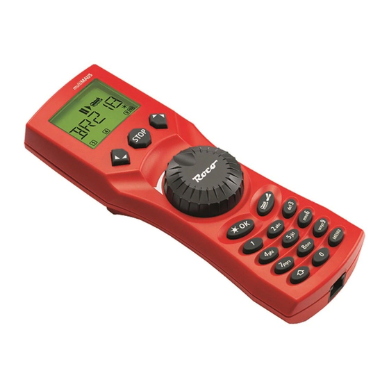
    Fig. 1 LC-Display Stop-Taste LC display Stop Key Écran touche »Stop« LC display Tasto di arresto Pfeiltaste (links) Pfeiltaste (rechts) Arrow Key (left) Arrow key (right) touche »flèche« touche »flèche« (à gauche) (à droite) Tasto freccia (sinistra) Tasto freccia (destra) Fahrregler control knob Licht / OK-Taste...
  • Seite 3 Setting up the ROCO digital system (Europe version with 230 V) with the multiMAUS. Structure de la commande numérique ROCO (version européene à 230 V) avec la multiMAUS (= multiSOURIS ). Struttura del sistema digitale ROCO (versione europea a 230 V) con il multiMAUS.
  • Seite 4 Fig. 3  Anschluss eines Boosters 10805 / Wiring diagram of the amplifier 10805 / Raccordementde la L'amplificateur numérique complémentaire ref. 10805 (Booster) Allacciamento del booster 10805 8051281925.indd 4 10.05.2016 12:52:09...
  • Seite 5 Fig. 4 Eine digitale Kehrschleife mit den Kehrschleifenmodulen 10769 (werkseitig ausverkauft) oder 10767. A digital turning loop with the turning loop control module 10769 (sold out by the factory) or 10767. Branchement d‘une boucle de retournement en commande numérique contrôlée par les modules 10769 (vendu en usine) ou 10767.
  • Seite 6: Inhaltsverzeichnis

    1. Das „Lok“-Menü 2. Das Menü „Programmieren“ 3. Das Menü „Einstellungen“ Teil 3 Anhang – Wissenswertes rund um die multiMAUS und das Thema Digital ▪ Kompatibilität der multiMAUS – alle verwendbaren Geräte Lokomotiven ohne Digitaldecoder und die multiMAUS Die Z21-Booster...
  • Seite 7: Die Evolution Der Roco Lokmaus - Die Multimaus

    Die Evolution der ROCO Lokmaus — die multiMAUS In der multiMAUS vereinigen sich die Funktionalität der legendären Lokmaus mit dem Komfort einer aus- gewachsenen Digital-Zentrale. Ob Sie die multiMAUS nur als komfortablen Fahrregler nutzen, oder Ihre Lokdecoder und Weichen umfassend programmieren wollen, das übersichtliche Design in Verbindung mit der einfachen Bedienung macht die multiMAUS zu einem Maßstab für digitale Modellbahnsteuerungen.
  • Seite 8: Teil 1 ▪ Grundlagen

    2. In die Buchse „DC-Power“ stecken Sie den Hohlstecker, der über das zweipolige Kabel mit dem Schaltnetzteil verbunden ist. 3. Verbinden Sie die multiMAUS und die Z21 mit dem mitgelieferten Kabel. Stecken Sie das Kabel in die mit „X-BUS“ bezeichnete Anschlussbuchse der Z21.
  • Seite 9: Das Display

    „PROGRAMMIEREN“ Die Tasten Zu dem übersichtlichen Konzept der multiMAUS gehört die Reduzierung der Tasten auf eine sinnvolle Anzahl. Alle für den Spielbetrieb notwendigen Funktionen sind überwiegend direkt über die jeweiligen Tasten abruf- bar, die wir Ihnen hier vorstellen wollen. Beachten Sie dazu auch Fig. 1 auf Seite 3.
  • Seite 10 schaltet das Licht ein- oder aus (im Fahrbetrieb) ▪ Licht / OK bestätigt Eingaben (im Weichen-Modus und in den Menüs) ▪ aufrufen der gewünschten Menüebene bzw. der Menüpunkte ▪ in Kombination mit im Lokadress-Modus: Auswahl einer anderen Lok über direkte Eingabe einer Lokadresse ▪...
  • Seite 11: Die Bedienung Der Multimaus

    Die Bedienung der multiMAUS Trotz ihrer vielen Möglichkeiten ist die multiMAUS leicht und intuitiv bedienbar. Ein Konzept, das von ROCO schon mit den Lokmäusen der ersten und zweiten Generation erfolgreich eingeführt worden ist. Im Folgenden zeigen wir Ihnen an Hand praktischer Beispiele die Bedienung der multiMAUS.
  • Seite 12: Displaymeldung

    Sie die Taste „1“ öfter drücken. Eingabefeh- ler korrigieren Sie, indem Sie mit der linken „Pfeil- taste“ eine oder mehrere Stellen zurückgehen. Bestätigen Sie mit „OK“. Danach wechselt die multiMAUS auf die Lok- adresse. Angezeigt wird ein „Vorschlagswert“, hier „3“. 8051281925.indd 12...
  • Seite 13: Der Lokadress-Modus

    Die Lok kann nun gesteuert werden. 2.2. Der Lokadress-Modus Die multiMAUS bietet Ihnen auch die Möglichkeit, Ihre Loks einfach nur über die Decoder-Adresse zu steuern. Das Display zeigt Ihnen dabei die Lokadresse mit voran gestelltem „L“ – hier die Lokadresse 36, das Loksymbol sowie die ausgewählten Funktionen.
  • Seite 14: Fahren Und Funktionen

    Stillstand Vorwärts Wird eine Lok von einer anderen multiMAUS oder Lokmaus gesteuert, blinkt das Loksymbol. Die Lokfunktionen wie z. B. die Geräusche einer Sound-Lok, aktivieren Sie über die „Funktionstas- ten“. Die ersten 10 Funktionen können Sie direkt über die jeweiligen Tasten auslösen.
  • Seite 15: Die Nothalt-Funktionen

    Durch Drehen des Fahrreglers wird der Lokhalt aufgelöst, die Lok fährt wieder. Weichensteuerung Mit der multiMAUS können Sie bis zu 1.024 digitale Weichenantriebe mit echten Weichenadressen steuern, ohne dazu eine Lokadresse (wie bei der Lokmaus 2 / R3) verbrauchen zu müssen. Dazu kön- nen Sie jederzeit während des Fahrbetriebes durch Drücken der „Lok / Weichentaste“...
  • Seite 16 Eingabe Displaymeldung Bemerkung Nach Betätigung der „Lok / Weichentaste“ wechselt die multiMAUS aus dem Fahrbetrieb (Bibliotheks- oder Lokadress-Modus) in den Weichen-Modus. Es erscheint immer die zuletzt aufgerufene Wei- che, hier die Weiche „6“, Stellung „Gerade“. Die blinkende Einfügemarke signalisiert die Ein- gabebereitschaft für die Weichenadresse.
  • Seite 17: Schnellprogrammierung

    Digital-Lokomotive oder ein Weichendecoder über die Gleise oder andere Verdrahtung mit der Z21 verbunden oder die multiMAUS ist auf den „POM“-Modus umgestellt (siehe Teil 2). Wird die Programmierung auf dem normalen Fahrgleis durchgeführt und befindet sich mehr als eine Digital- Lokomotive auf dem Gleis (oder auch andere Weichendecoder als die ROCO-Artikel 42624 und 10775), werden mit einem Programmierbefehl die Einstellungen aller Decoder im System verändert.
  • Seite 18: Kurzschluss Und Überlastung

    CVs des Decoders auf die Werkswerte zurückgesetzt. Kurzschluss und Überlastung Tritt an der Anlage ein Kurzschluss oder eine Überlastung auf, so zeigt die multiMAUS dies im Display durch zwei blinkende Symbole an: einen Blitz und das STOP-Zeichen. Gleichzeitig wird die Stromversorgung der Anlage abgeschaltet.
  • Seite 19: Die Menü-Funktionen Der Multimaus

    Einhandbedienung der multiMAUS, gleichzeitiges Drücken der „Shift“- und der „MENU“-Taste. ▪ Die Steuerung einer Lok ist nicht möglich, während sich die multiMAUS im Menü-Modus befindet. Die interne Kommunikation mit einer weiteren multiMAUS oder anderen DCC-Geräten ist jedoch sichergestellt. oder ca.
  • Seite 20: Die Menüstruktur In Der Übersicht

    PROGRAMMIEREN CV ÄNDERN BEARBEITEN LANGE ADRESSE LÖSCHEN SUCHEN Grundsätzliche Hinweise zur Bedienung der Menü-Funktionen und zur Programmierung: Bewegen Sie sich innerhalb der Menü ebene ▪ (in dieser Übersicht also immer von oben nach unten), erreichen Sie die einzelnen Menüs durch Drücken einer der beiden SENDEN „Pfeiltasten“.
  • Seite 21 Systemeinstellungen Drücken der „STOP“-Taste nicht bestätigt. Bibliothek Programmieren Sie immer auf einem von der übrigen Anlagen vollständig abgetrennten Fahrstufen Programmiergleis (Ausnahme: Sie haben die Alles multiMAUS auf den POM-Modus (Seite 24) umgestellt). Kalibrieren Spannung Aus Nothalt STOP-MODUS Software X-BUS Zentrale 8051281925.indd 21...
  • Seite 22: Das „Lok"-Menü

    1. Das „Lok“-Menü Im „Lok“-Menü verwaltet die multiMAUS alle Daten, die für die Lok-Bibliothek und die Identifizierung einer Lok erforderlich sind. Auch können Sie hier die multiMAUS grundsätzlich auf Bibliotheks- oder Adress- Bedienung einstellen. 1.1. „NEU“ In diesem Menüpunkt können Sie eine neue Lok in die Bibliothek aufnehmen. Der Ablauf ist prinzipiell wie im ersten Teil auf Seite 12 beschrieben und dargestellt.
  • Seite 23 Geben Sie einfach eine Lokadresse über die „Funktionstasten“ ein und die multiMAUS sucht Ihnen die dazu gehörende Lok aus der Bibliothek heraus. Durch Drücken der „Licht / OK“-Taste bestätigen Sie die Eingabe. Die multiMAUS geht direkt zurück ▪ in den Lok-Modus und zeigt die zugeordnete Lok an.
  • Seite 24: Das Menü „Programmieren

    Digital-Lokomotive oder ein Weichendecoder über die Gleise oder andere Verdrahtung mit der Z21 verbunden oder die multiMAUS ist auf den „POM“-Modus umgestellt. Wird die Programmierung auf dem normalen Fahrgleis durchgeführt und befindet sich mehr als eine Digital-Lokomotive auf dem Gleis (oder auch andere Weichendecoder als die ROCO-Artikel 42624 und 10775), werden mit einem Programmierbefehl die Einstellungen aller Decoder im System verändert.
  • Seite 25 3. Das Menü „Einstellungen“ Das umfangreichste Menü der multiMAUS enthält alle Daten, die für die grundsätzliche Bedienung der multiMAUS praktisch, sinnvoll oder manchmal auch notwendig sind. Auch hier möchten wir darauf hin- weisen, dass die multiMAUS werkseitig schon mit allen erforderlichen Einstellungen versehen wurde, so dass Sie dieses Hauptmenü...
  • Seite 26: Das Menü „Einstellungen

    Ausgangsebene „AUTOMATIK“ zurück. 3.4. „FAHRSTUFEN“ Die Voreinstellung der Fahrstufen, mit der die multiMAUS die Lokdecoder ansteuert, erfolgt in diesem Menüpunkt (mehr zum Thema „Fahrstufen“ im Glossar im 3. Teil). Welche Fahrstufen Ihr Decoder verarbeiten kann, entnehmen Sie bitte der dazu gehörenden Betriebsanleitung.
  • Seite 27 3.5.4. Wählen Sie „FAHRSTUFEN“ aus, wird die in Menüpunkt 3.4. getroffene Auswahl auf den Werkswert zurück gesetzt. 3.5.5. Mit „ALLES“ setzen Sie Ihre multiMAUS komplett in den Ursprungszustand zurück. Alle jemals vorgenommenen Eintragungen werden dabei gelöscht. 3.5.6. „KALIBRIEREN“ müssen Sie die multiMAUS im Normalfall nicht, das wird bei der Auslieferung vorgenommen.
  • Seite 28: Teil 3 ▪ Anhang

    Systeme erhalten Sie bei den jeweiligen Herstellern oder bei Ihrem Fachhändler. Auf einer von der multiMAUS gesteuert Anlage können Sie nicht nur Loks mit ROCO-Lokdecodern einsetzen, sondern auch Fahrzeuge mit Decodern anderer Hersteller, wenn diese der NMRA / DCC-Norm entsprechen.
  • Seite 29: Die Z21-Booster

    Zum Einbau des Boosters schalten Sie die Anlage aus. Teilen Sie die Anlage in Versorgungsabschnitte auf. Trennen Sie an den entsprechenden Stellen die Gleise elektrisch voneinander (beidseitig!) entweder mit den ROCO Isolier-Schienenverbindern 42611 oder 61192, mit Trenngleisen oder indem Sie die Schienenprofile aufsägen. Bauen Sie in den neuen Versorgungsabschnitt ein Anschluss-Gleisstück (z. B. Einspeisungselement 61190) ein und schließen Sie es am Booster an die Buchse „Track Out“...
  • Seite 30: Kehrschleifen Im Digitalbetrieb

    Alle Werte, die das Verhalten des Lokdecoders – und somit letztendlich das Verhalten der Lok – beeinflus- sen, werden in sogenannten CVs hinterlegt. CV ist die Abkürzung für Configuration Variables, was man mit Konfigurations-Werte übersetzen kann. Da die multiMAUS und die Z21 kompatibel zum NMRA / DCC- Standard sind, können sie diese CVs lesen und schreiben.
  • Seite 31: Smart-Search-Funktion

    Signale aus „Nullen“ und „Einsen“ bestehen, sind sie abgestuft. Je kleiner die Stufen – Fahrstufen – sind, umso feiner lässt sich die Lok regeln. Die NMRA / DCC-Norm, nach der die multiMAUS arbeitet, kennt 14, 27, 28 oder 128 Fahrstufen.
  • Seite 32: Programmierhilfe Lokmaus 2 / R3 - Multimaus

    (siehe Seite 24) Umstellung Fahrstufen Viele Tipps und Infos zum Thema Modellbahnelektrik und Digital finden Sie im großen ROCO Elektrik- handbuch, Artikel-Nummer 82071, das Sie als CD-ROM im Fachhandel erhalten. Auch die ROCO Anlagensteuerung ROCOMOTION bietet vielfältige Möglichkeiten, auch zusammen mit der multiMAUS.
  • Seite 33: Fehlermeldungen

    Gerät aus und wieder ein. Sollte der Fehler dann noch nicht behoben sein, prüfen Sie die X-BUS-Adresse. ERR 14: Die Kalibrierungswerte sind ungültig. Der Fahrregler muss neu kalibriert werden. Beachten Sie dazu Seite 27, 3.5.6. ab ERR 90: Ihre multiMAUS ist leider zum Service-Fall geworden und braucht eine Grundüberholung im ROCO-Service. 8051281925.indd 33 10.05.2016 12:52:15...
  • Seite 34 Table of Content The evolution of the ROCO Lokmaus — the multiMAUS An overview of the multiMAUS Section 1 Basics – Get to know the multiMAUS ▪ Connecting the multiMAUS The Display Screen The Keys Operating the multiMAUS 1. Start 2.
  • Seite 35: The Evolution Of The Roco Lokmaus - The Multimaus

    The multiMAUS brings together the functionality of the legendary Lokmaus with the comfort of a fully digital central control unit. Whether you use the multiMAUS as just a comfortable controller or wish to use it for comprehensive programming of your locomotive decoder and turnouts, the clear layout of the design and simple operation make the multiMAUS the leading digital model railroading controller.
  • Seite 36: Connecting The Multimaus

    2. Plug the hollow plug, which is connected to the switching power supply by the two-pin cable, into the “DC-Power” socket. 3. Connect the multiMAUS and the Z21 using the cable included with your system. Plug the cable into the connection socket on the Z21 labeled “X-BUS”.
  • Seite 37: The Display Screen

    The Display Screen All the functions of the multiMAUS can be checked on the large LCD with backlight. The symbols are as follows: Drive symbols Wrench Turnout symbol Arrows shows the direction of the multiMAUS is in the (locomotive / turnout key) ▪...
  • Seite 38 Switch the light on or off (in drive mode) ▪ Light / OK key Confirm inputs (in turnout mode and in the menus) ▪ Call up desired menu level or menu items ▪ in combination with In locomotive address mode: Shift key Select another locomotive by directly inputting an locomotive address ▪...
  • Seite 39: Operating The Multimaus

    “LOK 1” so that you can drive the locomotive immediately. If you have purchased the multiMAUS with a starter set, the locomotive from the set is already fully programmed. You can also drive this locomotive immediately (section 3).
  • Seite 40 “1” key. Correct input errors by us- ing the left “arrow key” to move back one or more spaces. Confirm by pressing “OK” The multiMAUS then switches to the locomo- tive address. The “suggested value” is dis- played, in this case “3”. 8051281925.indd 40...
  • Seite 41 2.2. Locomotive address mode The multiMAUS also gives you the option of controlling your loco- motives using the decoder address only. The display screen shows the locomotive address with the letter “L” before it (in this case, locomotive address 36), the locomotive symbol and all the selected functions.
  • Seite 42: Driving And Functions

    Backwards Standstill Forwards If another multiMAUS or Lokmaus is used to control a locomotive, the locomotive symbol flashes. The locomotive functions, e.g. the noises of a sound locomotive, are activated using the „function keys“. You can trigger the first 10 functions directly by pressing the corresponding keys. For functions F11 –...
  • Seite 43: The Emergency Stop Functions

    The locomotive stop is released by turning the controller, the locomotive starts to move again. Turnout control You can use the multiMAUS to control up to 1,024 digital turnout drives with genuine turnout ad- dresses without having to use up a locomotive address (as is the case with the Lokmaus 2 / R3). To do so, you can switch to turnout mode and back at any time by pressing the “Locomotive / turnout”...
  • Seite 44 Input Display message Comment After the “Locomotive / turnout” key has been pressed, the multiMAUS switches from drive mode (library or locomotive address mode) to turnout mode. The turnout last called up always appear. In this case, turnout “6”, position “straight-on”.
  • Seite 45: Quick Programming

    This provides you with quick access to two sets of turnouts which, for instance, are next to each other on a stretch of track. Address scrolling Press the “shift” key and one of the “arrow keys” at the same time and the multiMAUS will scroll through all the turnout addresses. Turnout short-cut keys For quick access you can store the 10 most frequently used turnouts as a short-cut function on the “function keys”.
  • Seite 46: Short Circuit And Overload

    Short circuit and overload If a short circuit or an overload occurs on the system, the multiMAUS indicates this using two flashing symbols on the display screen: a streak of lightning and the STOP symbol At the same time the voltage supply to the system is shut off.
  • Seite 47: The Menu Functions Of The Multimaus

    Press the “MENU” key (alone or together with the shift key) to exit all levels immediately and return ▪ to locomotive and turnout mode. All of the menus of the multiMAUS can be found in the large overview on the next two pages. 8051281925.indd 47 10.05.2016 12:52:17...
  • Seite 48: Overview Of The Menu Structure

    PROGRAM CV MODIFICATION EDIT LONG ADDRESS DELETE SEARCH Basic instructions for operating the menu functions and programming: Move within the menu level (i.e. in ▪ this overview, from top to bottom) to access the individual menus by pressing one of the two arrow keys. SEND By pressing the “Light / OK”...
  • Seite 49 “STOP” key. Library Always program on a programming track which is fully disconnected from the rest of the system Speedsteps (exception: you have switched the multiMAUS to POM mode (page 52). Factory Reset Calibration Disable Voltage...
  • Seite 50: The "Loco" Menu

    1. The “Loco” Menu The multiMAUS uses the “LOCO” menu to manage all data which is required for the locomotive library and for identification of a locomotive. You can also use this menu to set the multiMAUS to library or ad- dress mode.
  • Seite 51 1.4. “SEARCH“ This could be one of the most important functions of your multiMAUS. You can use this menu item to assign a locomotive address to the corresponding locomotive in the library. Simply enter a locomotive address using the “function keys” and the multiMAUS will find the cor- responding locomotive in the library.
  • Seite 52: The "Program" Menu

    Programming has to be performed on a separate programming track unless there is only one digital locomotive or turnout decoder connected to the Z21 by the tracks or other wiring or if the multiMAUS is switched to “POM” mode (see section 2). If programming is performed on the normal driving track...
  • Seite 53: The "Settings" Menu

    The most extensive multiMAUS menu contains all the data which is practical, useful or sometimes nec- essary for basic operation of the multiMAUS. We would also like to point out at this point that the multiMAUS is provided with all the necessary settings in the factory so that you have to use this main menu either rarely or not at all.
  • Seite 54 3. The “Settings” Menu 3.2.4. The multiMAUS has „CHILD LOCK“ which can be set to multiple levels and can be activated after calling up the menu item using the „arrow keys“. To block an area, you will need to enter a code which is comprised of 4 numbers (no letters!).
  • Seite 55 3. The “Settings” Menu 3.5. “RESET“ The multiMAUS is a particularly user-friendly digital controller and can be reset to the factory set- tings, not just completely but also partially. 3.5.1. “CANCEL” can be regarded as the emergency exit from this menu item.
  • Seite 56: Multimaus Compatibility - All Useable Devices

    Appendix ▪ multiMAUS Compatibility – all useable devices 1. Previous Lokmaus systems All ROCO digital devices which are based on X-BUS technology can be combined with the multiMAUS. These include: multiZENTRALE ▪ Lokmaus 2 / PowerMouse / Lokmaus R3: 10760 / 10790 / 10860 / 10792, ▪...
  • Seite 57: The Z21-Booster

    (on both sides). Complete this task by using either the ROCO isolating rail joiners 42611 or 61192 or separating tracks or by cutting open the track profiles. Install a connection track piece (e.g. supply element 61190) into the new supply section and connect it to the "Track Out"...
  • Seite 58: Terminal Loops In Digital Operation

    The ROCO 10767 terminal loop module solves the problems of a terminal loop in digital operation. Isolate the terminal loop with both poles on both sides by disconnecting the terminal loop completely from the rest of the system, using either insulated connectors or by sawing the rail profiles (see fig.
  • Seite 59: Glossary

    All values which affect the behaviour of the locomotive decoder – and ultimately the behaviour of the locomotive – are stored in what are referred to as CVs. CV is the abbreviation for configuration variables. You can read and write these CVs as the multiMAUS and the Z21 are compatible with the NMRA / DCC standard.
  • Seite 60: Hints, Tips And Help

    Z21 digital control centre). The Z21 also generates the digital track system (and much more).  X-BUS The X-BUS is the connection between the digital components (multiMAUS, booster, interface etc.) and not only supplies voltage but is also responsible for data exchange.
  • Seite 61: Programming Help For Lokmaus 2 / R3 - Multimaus

    Lokmaus 2 / R3. The following includes a table which compares the programming procedure for the Lokmaus 2 / R3 and quick programming (see page 45) on the multiMAUS. For more information see the operating manual for the Lokmaus 2 / R3. To program CV29 see the operating instructions included with the decoder.
  • Seite 62: Error Messages

    ERR 4: Not possible in “POM” mode. This error occurs if the multiMAUS is changed over to “POM” mode (page 52) when you are intending to program CV1 (locomotive address). Program CV1 on a separate section of pro- gramming track in “CV mode” (see page 52).
  • Seite 63 8051281925.indd 63 10.05.2016 12:52:19...
  • Seite 64 Table des matières L’évolution de la loco-souris de ROCO — la multiSOURIS La multiSOURIS en un clin d’oeil Chapitre 1 Les bases – Faites connaissance avec la multi SOURIS ▪ Raccordement de la multiSOURIS L’écran d’affichage Les touches Le maniement de la multiSOURIS 1.
  • Seite 65: L'évolution De La Loco-Souris De Roco - La Multisouris

    DCC/NMRA ▪ permet l’intégration au système ROCO de commande numérique de 31 autres appareils de com- ▪ mande tels que d’autres loco-souris et multiSOURIS , claviers numériques »appareils de voie« ou »Route Control«, etc.
  • Seite 66: Raccordement De La Multisouris

    La prise »X-BUS« de l’amplificateur permet le raccordement d’une autre multiSOURIS , d’une loco-souris des types »2« et »R3«, d’un clavier numérique ROCO, du clavier »RouteControl« (réf. 10772) ou, à l’aide de l‘interface et du logiciel »ROCOMOTION«, d’un ordinateur PC. Lors de cette opération laisser exceptionnellement sous tension votre commande numérique, car uniquement de...
  • Seite 67: L'écran D'affichage

    L’écran d’affichage Toutes les fonctions activées de la multiSOURIS sont visualisées sur le grand écran à cristaux liquides avec éclairage translucide et vous permettent ainsi un contrôle aisé. Ci-dessous nous vous présentons les symboles : Symboles de circulation clé à fourche symbole »aiguillage«...
  • Seite 68 parcourir la bibliothèque »matériel moteur« (mode »bibliothèque«) ▪ Chercher l’adresse d’une machine (mode »adresses machines«) ▪ Commande d’un aiguillage (»droit« ou »dévié«, mode »aiguillages«) ▪ touches »flèches« feuilleter un menu primaire ou secondaire ▪ combinée avec mode »bibliothèque« activé : Modifier l’ordre des machines par déplacement d’une machine ▪...
  • Seite 69: Le Maniement De La Multisouris

    Dotée de nombreuses possibilités, la multiSOURIS est néanmoins d’un maniement facile et intuitif. Cet esprit fut déjà appliqué par ROCO lors de la réalisation des loco-souris de première et deuxième générations. Les exemples suivants vous montrent et expliquent le maniement de la multiSOURIS En cas de problèmes lors du maniement ou de la programmation se référer aux pages 92 et suivantes qui four-...
  • Seite 70: Comment Appeler Une Machine

    1.2. Mise en service d’une multiSOURIS déjà utilisée Si la multiSOURIS a déjà été utilisée au moins une fois, elle vous affiche, dès le nouvel allumage, la dernière machine commandée lors de la séance précédente et se commute au dernier mode enclenché...
  • Seite 71 Enregistrement d’une machine (ici le RGP TEE de la SNCF, série X 2771 à 2781) : Touches actionnées Affichage corres- Remarque pour saisir les données pondant à l’écran La place libre pour saisir les données de la machine est affichée à l’écran par la mention »NOUV«;...
  • Seite 72: Marche Et Fonctions Secondaires

    Confirmer, de nouveau, par la touche »OK«. La sélection du régime des  crans de marche se fait par les touches »flèches«. Il existe 3 régimes : 14, 28 ou 128 crans. En usine la multiSOURIS est programmé en régime »28 crans«. Si vous aviez déjà...
  • Seite 73: Marche Arrière

    Machine à l’arrêt (l’écran affiche le symbole »II«) l’écran indique le dernier sens de circulation de la machine. On peut ainsi facilement vérifier si les feux, éventuellement éclairés, correspondent effecti- vement au sens de marche de la machine, donc »feux blancs« en tête du convoi et »feux rouges« à l’arrière.
  • Seite 74: La Commande Des Aiguillages

    4.1. Arrêt d’urgence général En pressant la touche »STOP« vous coupez immédiatement le courant dans la voie, le symbole »STOP« se met à clignoter. La touche »STOP« une deuxième fois actionée, vous rétablissez l’alimentation. STOP STOP 4.2. Arrêt d’urgence sélectif L’arrêt d’urgence sélectif ne s’adresse qu’à...
  • Seite 75 Les aiguilles changent de position au moment ou vous pressez une des deux touches »flèches«. En même temps, la nouvelle position des aiguilles est mémorisée par la multiSOURIS et confirmée par la mise à »0« des premiers chiffres libres suivant la lettre »A«, si l’adresse du moteur n’a que trois chiffres maxi. L’affichage de la position des aiguilles à...
  • Seite 76: Programmation Rapide

    être interrompue en appuyant brièvement sur la touche Stop Z21. Les décodeurs installés en usine dans des locomotives ROCO sont livrés avec des CV programmées à des valeurs adaptées au mieux aux caractéritiques de la machine. Veuillez donc vérifier, avant toute modification, si une telle modification des données est effectivement nécessaire.
  • Seite 77: L'écran Affiche

    À noter : Pour programmer une machine , déconnectez le réseau de l’amplificateur et raccordez une voie »programmation«, électriquement entièrement isolée du réseau, à l’amplificateur ou prévoyez une voie bipolairement isolée du réseau par des éclisses isolantes et commutable sur l’amplificateur par un inverseur également bipolaire qui coupe ainsi le reste du réseau.
  • Seite 78: Les Menus De La Multisouris Et Leurs Fonctions

    Chapitre 2 Les menus ▪ Les menus de la multiSOURIS et leurs fonctions La multiSOURIS dispose de trois menus principaux vous permettant une programmation complexe et une modification facile des données de base de la multiSOURIS Vous avez accès aux menus principaux par deux différentes combinaisons de touches à...
  • Seite 79: La Structure Des Menus De La Multisouris En Un Coup D'oeil

    PROGRAMMER MODIFIER VARIABLE NOUVELLE MODIFIER ADRESSE LONGUE Variable Programmer en EFFACER Ligne CHERCHER Quelques remarques fondamentales concernant l’activation des différentes fonctions des menus et la programmation: Autant que vous restez sur le même niveau ▪ hiérarchique des menus (dans cette illustra- tion les niveaux sont présentés en verticale ENVOYER pour des raisons de place), vous sélection-...
  • Seite 80 Eclairage Contraste REGLAGES ECRAN Langue Delai Touche Menu MANIEMENT Fonction Touche Verrouillage Recherche Rapide Adresse Automatique »0« dont le numéro correspond au numéro du menu secondaire souhaité. CRANS DE MARCHE En pressant la touche »STOP« vous retour- ▪ nez toujours au menu supérieur dans la hiérarchie.
  • Seite 81: Le Menu Principal »Loco

    1. Le menu principal »LOCO« Le menu »LOCO« vous permet de faire gérer par votre multiSOURIS toutes les données indispensables pour la bibliothèque »matériel moteur« et pour l’identification d’un engin moteur. Ce menu vous permet également de préenclencher la multiSOURIS aux modes »bibliothèque« ou »adresses machines«. 1.1.
  • Seite 82 1. Le menu principal »LOCO« 1.3. »EFFACER« Ce menu secondaire vous permet de supprimer une machine de la bibliothèque. La première vue affichée vous présente la machine dernièrement commandée au régime »exploita- tion«. Par les touches »flèches« vous parcourez la liste et choisissez la machine dont les données sont à...
  • Seite 83: Le Menu Principal »Programmer

    La lecture peut être interrompue en appuyant brièvement sur la touche Stop Z21. Les décodeurs installés en usine dans des locomotives ROCO sont livrés avec des CV programmées à des valeurs adaptées au mieux aux caractéritiques de la machine. Veuillez donc vérifier, avant toute modification, si une telle modification des données est effectivement nécessaire.
  • Seite 84: Le Menu Principal »Reglages

    par les touches des fonctions »1« à »0«. Dès que vous avez composé le premier chiffre de la nouvelle adresse, les chiffres de l’adresse proposée disparaissent de l’écran. Confirmer la nouvelle adresse par la touche »feux / OK«. Avant de retourner définitivement au départ du ▪...
  • Seite 85 . Sélectionner la langue souhaitée par les touches »flèches«. Si votre langue préférée n’est pas mémorisée, consulter le site www.roco.cc (actuellement ce site n’existe qu’en langues alle- mande et anglaise) pour y trouver une possibilité éventuelle de mise à jour.
  • Seite 86 Confirmer par la touche »feux / OK« votre choix préalablement fait à l’aide des touches »flèches«. ▪ La multiSOURIS retourne au départ du menu secondaire »RECHERCHE RAPIDE«. 3.3. »X-BUS« Le »X-BUS« est le protocole permettant la communication entre les différents composants de la com- mande numérique (la multiSOURIS »maître«, par exemple, avec l’amplificateur numérique ou une multiSOURIS »esclave«).
  • Seite 87 »matériel moteur« sont conservées. S’il y a eu un calibrage de la multiSOURIS (voir 3.5.6. en bas) un nouveau calibrage devient éventuellement nécessaire après la réinitialisation de la multiSOURIS par cette fonction. 3.5.3. La fonction »BIBLIOTHÈQUE« : Si vous voulez uniquement effacer la bibliothèque »matériel moteur«...
  • Seite 88: Compatibilité De La Multisouris

    ROCO. Si ces machines disposent, à leur tour, de l’interface normalisée, l’installation d’un décodeur devient aussi facile que pour les locomotives ROCO. Si vous voulez installer un décodeur »traction« avec compensation de charge (réf. 10884), il est indispensable que la machine dispose d’un moteur »courant continu«.
  • Seite 89: L'amplificateur Numérique Complémentaire (»Booster«)

    électriquement aux points correspondants les voies les unes des autres (des deux côtés) soit avec les connecteurs de rail isolants ROCO 42611 ou 61192, avec des rails de sectionnement ou en sciant les profils de rails. Montez dans la nouvelle section d'alimentation une pièce de voie de raccordement (par ex. pla- quette d'alimentation 61190) et raccordez-la à...
  • Seite 90: Boucles De Retournement En Commande Numérique

    Boucles de retournement en commande numérique Chaque modéliste »deux rails, courant continu« connaît le problème des boucles de retournement qui existe indifféremment pour des réseaux en analogique comme en numérique, car en commande numérique on a toujours le fait que le profilé situé à gauche avant l’entré en la boucle rencontre le profilé à droite à sa sortie et vice-versa.
  • Seite 91: Glossaire

    – sont stockées dans des variables »CV«. C’est une abréviation du terme informatique »Confi- guration Variable« = variable de configuration. Comme multiMAUS et la centrale Z21 sont compatibles avec NMRA / DCC-Standard, elles peuvent lire et écrire ces CV.
  • Seite 92: Astuces, Renseignements Et Petits Dépannages Rapides

    sera remplacée par celle de la machine la plus récemment appelée. La liste est réinitialisée à zéro à chaque démarrage de votre commande numérique (coupure d’alimentation de votre commande ou déconnexion puis reconnexion de la multiSOURIS raccordée à la prise »Master« de l’amplificateur numérique principal). La fonction »sélection rapide«...
  • Seite 93: Programmation De La Multisourispar Rapport Aux Loco-Souris Type »2« Et »R3

    Programmation de la multiSOURIS par rapport aux loco-souris type »2« et »R3« Les modes d’emploi des composants de la commande numérique ROCO commercialisés avant la multiSOURIS (le moteur d’aiguilles réf. 42624 avec décodeur intégré, par exemple) ne décrivent que le mode standard de programmation par les loco-souris des types »2«...
  • Seite 94: Codes D'erreurs

    Ce code s’affiche lorsqu’il faut un recalibrage de la multiSOURIS . Se référer au paragraphe 3.5.6. page 87. À partir du code »ERR 90« : votre multiSOURIS est malheureusement devenue futur cliente du S.A.V. ROCO et a besoin d’une révision à fond.
  • Seite 95 8051281925.indd 95 10.05.2016 12:52:24...
  • Seite 96 1. Il Menu “Locomotiva“ 2. Il Menu “Programmare“ 3. Il Menu “Regolazione” Parte 3 Appendice – Tutto quello che c’è da sapere sul multiMAUS ed la tematica digitale ▪ Compatibilita del multiMAUS Locomotive senza Decoder Digitale ed il multiMAUS Il Z21- Booster...
  • Seite 97: Panoramica Del Multimaus

    Nel multiMAUS si congiungono la funzionalità del leggendario Lokmaus con il comfort di una centrale digitale evoluta. Sia che si desideri utilizzare il multiMAUS solo come un comodo regolatore di guida o programmare in modo completo i vostri decoder e gli scambi, il design chiaro unito al facile utilizzo rende ilmultiMAUS un elemento fondamentale per i comandi digitali del modellismo ferroviario.
  • Seite 98: Collegamento Del Multimaus

    Parte 1 Elementi di Base ▪ Collegamento del multiMAUS La fig. 2 a pagina 3 mostra il collegamento di base. Per un sistema digitale ROCO funzionante con il multiMAUS sono necessari i seguenti articoli: La centrale Z21, ▪ un alimentatore 10851, ▪...
  • Seite 99 I Tasti Grazie al concetto chiaro del multiMAUS i tasti sono stati notevolmente ridotti. Tutte le funzioni necessarie sono richiamabili prevalentemente direttamente attraverso i relativi tasti che vi illustreremo. Osservare in merito anche la fig. 1 a pagina 2 Avvisi: I “tasti freccia“...
  • Seite 100 attiva o disattiva la luce (durante la marcia) ▪ conferma le immissioni (in modalità Scambi e nei menu) Tasto Luce / OK ▪ richiamo del piano di menu desiderato o delle voci di menu ▪ in combinazione con in modalità Indirizzo locomotiva: selezione di un’altra locomotiva attraverso l’immissione diretta di un ▪...
  • Seite 101: Primo Impiego

    Nonostante le molte funzionalità il multiMAUS è facile ed intuitivo da utilizzare. Un concetto introdotto con successo dalla ditta ROCO già con i Lokmaus di prima e seconda generazione. Di seguito illustreremo sulla base di esempi pratici il funzionamento del multiMAUS.
  • Seite 102 “1“. Gli errori di immissione possono essere corretti ritornando con il “tasto freccia“ sinistro di uno o più posizioni. Confermare con “OK“ Il multiMAUS passa quindi all’indirizzo della locomotiva. Viene visualizzato un “valore di suggerimento“, qui “3“. 8051281925.indd 102...
  • Seite 103 Modificare il “valore di suggerimento“ utiliz- zando il tasto „Maiusc“ ed un “tasto freccia“ o immettendo direttamente il numero con i “tasti oppure funzione“. … Questa modifica ha effetti solo sull’assegna- zione dei nomi nell’archivio! L’indirizzo del decoder deve essere modificato con il CV1 (vedi paragrafo 6, pagina 107).
  • Seite 104 Indietro Arresto Avanti Quando una locomotiva è controllata da un altro multiMAUS o Lokmaus, lampeggia il simbolo della locomotiva. Le funzioni della locomotiva, quali ad es. i rumori di una locomotiva sonora, possono essere attivate con i “tasti funzione“. Le prime 10 funzioni possono essere attivate direttamente con i relativi tasti.
  • Seite 105: Arresto Di Emergenza

    Ruotando il regolatore di marcia viene annullato l’arresto e la locomotiva continua a correre. Comando degli scambi Con il multiMAUS è possibile controllare fino a 1.024 scambi digitali con veri indirizzi di scambi senza dover utilizzare un indirizzo di una locomotiva (come per il Lokmaus 2 / R3). Durante la marcia è...
  • Seite 106 Immissione Messaggio display Nota Dopo aver premuto il tasto “Locomo- tiva / Scambio” il multiMAUS passa dalla moda- lità di marcia (modalità Archivio o Indirizzo loco- motiva) alla modalità Scambi. Viene visualizzato sempre l’ultimo scambio richia- mato, qui lo scambio “6“, posizione “Diritta“.
  • Seite 107 è commutato in modalità “POM” (vedi Parte 2). Nel caso in cui la programmazione venga eseguita sul binario di marcia normale e su di esso è...
  • Seite 108 Corto circuito e sollecitazione eccessiva Quando nell’impianto si verifica un corto circuito o un sovraccarico, il multiMAUS lo segnala sul display attraverso due simboli lampeggianti: un lampo ed il simbolo dello STOP. Contemporaneamente viene interrotta l’alimentazione elettrica dell’impianto.
  • Seite 109: Le Funzioni Di Menu Del Multimaus

    “Maiusc” e “MENU”. ▪ Il comando di una locomotiva non è possibile mentre il multiMAUS si trova in modalità Menu. Tuttavia è assicurata la comunicazione interna con un altro multiMAUS o altri dispositivi DCC. MENU oppure ca.
  • Seite 110 PROGRAMMARE MODIFICARE CV LOCOMOTIVA MODIFICARE INDIRIZZO LUNGO Programmare in CANCELLARE Linea CERCARE Avvertenze di base per l’utilizzo delle fun- zioni di menu e per la programmazione: quando ci si sposta all’interno del ▪ piano di meni (in questa panora- mica quindi sempre dall’alto verso il basso), si raggiungono i singoli INVIARE menu premendo uno dei due “tasti...
  • Seite 111 Livelli di Marcia confermata premendo il tasto “STOP”. Effettuare la programmazione sempre su uno dei binari di Tutto programmazione scollegati completamente Calibrare dall’impianto (eccezione: il multiMAUS è stato commutato in modalità POM (pagina 116). Spento Arresto d’ emergenza STOP-MODALITA Software...
  • Seite 112 1. Il Menu “Locomotiva“ Nel menu „Locomotiva“ il multiMAUS gestisce tutti i dati necessari per l’archivio delle locomotive e per l’identificazione di una locomotiva. Il multiMAUS può essere impostato anche per il funzionamento ad Archivio o Indirizzo. 1.1. “NUOVO“ In questa voce di menu è possibile inserire nell’archivio una nuova locomotiva. La sequenza è princi- palmente come descritta ed illustrata nella prima parte a pagina 102.
  • Seite 113 Nel caso in cui il multiMAUS non riesca a trovare per l’indirizzo la locomotiva adatta, sul display sarà visualizzata la voce “ERR 9”. Con il tasto “STOP” o “Luce / OK” si ritorna al livello di partenza “CERCARE”.
  • Seite 114 è commutato in modalità “POM” (vedi Parte 2). Nel caso in cui la programmazione venga eseguita sul binario di marcia normale e su di esso è presente più...
  • Seite 115 ▪ 3. Il Menu “Regolazione” Il menu più completo del multiMAUS contiene tutti i dati pratici, utili o necessari per il funzionamento di base del multiMAUS. Desideriamo ricordare anche qui che il multiMAUS è stato preimpostato in fabbrica con le necessarie impostazioni in modo tale che il menu principale non debba essere utilizzato mai se non raramente.
  • Seite 116 3.3. “X-BUS“ “X-BUS“ è la lingua di collegamento con la quale i componenti digitali come il multiMAUS comu- nicano fra loro. Nelle due sottovoci “INDIRIZZI“ ed “AUTOMATICO“ un utente professionista ha la possibilità di cogliere tutte le informazioni e le impostazioni (maggiori informazioni nel glossario nella 3.
  • Seite 117 3.4. “LIVELLI DI MARCIA” La preimpostazione dei livelli di marcia con la quale il multiMAUS controlla il decodificatore della locomotiva avviene in questa voce di menu (maggiori informazioni sul tema „Livelli di marcia“ sono riportati nel glossario nella 3. parte). I livelli di marcia che il Vostro decodificatore può elaborare sono riportati nel relativo manuale d’uso.
  • Seite 118 Ruotare il regolatore di marcia al centro (posizione zero) e confermare con il tasto “Luce / OK“. Sul ▪ display appare “DESTRA”. Ruotare il regolatore di marcia fino alla battuta di arresto verso destra. Dopo aver confermato con il ▪ tasto “Luce / OK“...
  • Seite 119 Appendice ▪ Compatibilita del multiMAUS 1. I sistemi Lokmaus finora disponibili Tutti i dispositivi digitali ROCO che si basano sull’X-BUS possono essere combinati con il multiMAUS. Tra questi vi sono: multiZENTRALE ▪ il Lokmaus 2 / PowerMouse / Lokmaus R3 10760 / 10790 / 10860 / 10792, ▪...
  • Seite 120 In questo caso è presente un sovraccarico causato da troppe utenze (locomotiva, carrozze illuminate, ecc.). Il Booster insieme ad un ulteriore trasformatore (ROCO 10851) mette a disposizione ulteriore energia ed annulla in questo modo il sovraccarico.
  • Seite 121: Anelli Di Ritorno In Funzionamento Digitale

    Il modulo ad anello della ROCO 10769 rimuove per il funzionamento digitale i problemi di commutazione di un anello di ritorno. Scollegare elettricamente l’anello di ritorno sui due lati in modo bipolare impiegando dei connettori isolanti o segando i profili dei binari isolandoli completamente dal resto dell’impianto (vedi...
  • Seite 122 Con gli amplificatori ROCO 10761 e 10764 una lettura dei CV di un decoder non è possibile! Sono visualizzati solo valori di suggerimento fittizi. I CV possono presentare un campo di valori compreso tra “0“ e “255“. Ciò rende evidente che una modifica della programmazione presuppone una certa esperienza, poiché...
  • Seite 123: Suggerimenti, Avvisi E Breve Guida

    117) del multiMAUS quando si reinserisce il cavi premere contemporane- amente i tasti “Maiusc“ e “MENU“. Il multiMAUS viene riportato completamente alle impostazioni da fabbrica. Poiché in questo caso viene cancellato anche l’archivio delle locomotive è necessario pensarci bene ad eseguire questa oper- azione.
  • Seite 124 Guida di Programmazione Lokmaus 2 / R3 – multiMAUS Nelle istruzioni relative agli articoli digitali ROCO finora riportate (quali ad es. l’azionamento degli scambi 42624) hanno riguardato solo il modo di programmazione standard con il Lokmaus 2 / R3. Di seguito è...
  • Seite 125: Messagi Di Errore

    ERR 4: Impossibile in modalità “POM“. Questo errore si verifica quando il multiMAUS è stato commutato in modalità “POM“ (pagina 115) ed il CV1 (indirizzo della locomotiva) deve essere programmato. Programmare il CV1 su un binario di programmazione a parte in “Modo CV“ (vedi pagina 115).
  • Seite 126 8051281925.indd 126 10.05.2016 12:52:29...
  • Seite 127 8051281925.indd 127 10.05.2016 12:52:29...
  • Seite 128 Kurzübersicht / Overview Fahren / Driving Lokauswahl Nothalt Licht Loco selection Emerg. Stop Light Funktionen / Functions … … F1 – F10 F11 – F20 Weichen / Turnouts … Menüebene / Menu level oder zurück = back = PROGRAMMIEREN EINSTELLUNGEN Änderungen von Konstruktion und Ausführung vorbehalten!

Inhaltsverzeichnis