Inhaltsverzeichnis
Werbung
Verfügbare Sprachen
Verfügbare Sprachen
Quicklinks
T E C H N O L O G Y F O R T H E W E L D E R ´ S W O R L D .
DE Betriebsanleitung / EN Operating instructions
FR Mode d´emploi / ES Instructivo de servicio
IT Istruzioni per l'uso
iROB Feed 22/MP
DE Drahtvorschub
EN Wire feeder
FR Dévidoir
ES Devanadora o alimentador
IT Dispositivo di avanzamento del filo
DIN EN
ISO 9001
www.binzel-abicor.com
Werbung
Kapitel
Inhaltsverzeichnis
Fehlerbehebung

Verwandte Anleitungen für Abicor Binzel iROB Feed 22/MP


Inhaltszusammenfassung für Abicor Binzel iROB Feed 22/MP
- Seite 1 T E C H N O L O G Y F O R T H E W E L D E R ´ S W O R L D . DE Betriebsanleitung / EN Operating instructions FR Mode d´emploi / ES Instructivo de servicio IT Istruzioni per l‘uso iROB Feed 22/MP DE Drahtvorschub EN Wire feeder FR Dévidoir...
-
Seite 2: Inhaltsverzeichnis
Produktes erforderlich werden. Diese Änderungen werden jedoch in neuen Ausgaben berücksichtigt. Alle in der Betriebsanleitung genannten Handelsmarken und Schutzmarken sind Eigentum der jeweiligen Besitzer/Hersteller. Unsere aktuellen Produktdokumente, sowie alle Kontaktdaten der ABICOR BINZEL Ländervertretungen und Partner weltweit, finden Sie auf unserer Homepage www.binzel-abicor.com... -
Seite 3: Sicherheit
• iROB Feed 22 zur Verwendung für Push-Pull Anwendungen. • iROB Feed MP Master Pull, ohne zusätzliches Drahtvorschubsystem. Es darf nur in Verbindung mit der Roboterschweißstromquelle iROB Pulse und mit Original ABICOR BINZEL Ersatzteilen verwendet werden. Diese Betriebsanleitung beschreibt nur das Drahtvorschubgerät iROB Feed. 1.1 CE-Zeichen Dieses Gerät erfüllt die Anforderungen der einschlägigen EU- Richtlinien:... -
Seite 4: Persönliche Schutzausrüstung (Psa) De
2 Sicherheit iROB Feed 2.3 Persönliche Schutzausrüstung (PSA) Um Gefahren für den Nutzer zu vermeiden wird in dieser Anleitung das Tragen von persönlicher Schutzausrüstung (PSA) empfohlen. • Sie besteht aus Schutzanzug, Schutzbrille, Atemschutzmaske Klasse P3, Schutzhandschuhen und Sicherheitsschuhen. 2.4 Klassifizierung der Warnhinweise Die in der Betriebsanleitung verwendeten Warnhinweise sind in vier verschiedene Ebenen unterteilt und werden vor potenziell gefährlichen Arbeitsschritten angegeben. -
Seite 5: Warn- Und Hinweisschilder De
iROB Feed 2 Sicherheit • Alle Metalldämpfe, besonders Blei, Cadmium, Kupfer und Beryllium, sind gesundheitsschädlich! Sorgen Sie für ausreichende Belüftung oder Absaugung. Achten Sie immer auf die Einhaltung der gesetzlichen Grenzwerte. • Spülen Sie Werkstücke, die mit chlorierten Lösungsmitteln entfettet wurden, mit klarem Wasser ab. Ansonsten besteht die Gefahr der Phosgengasbildung. -
Seite 6: Produktbeschreibung
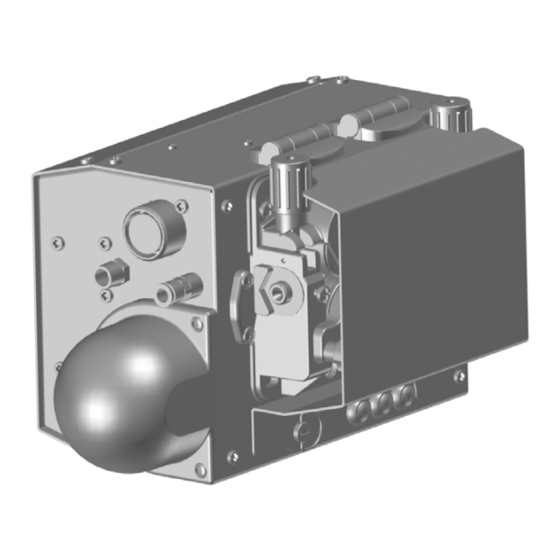
3 Produktbeschreibung iROB Feed 3 Produktbeschreibung 3.1 Technische Daten Abb. 1 Abmessungen iROB Feed 22 Abb. 2 Abmessungen iROB Feed MP DE - 6 BAL.0331.0 • 2017-08-31... -
Seite 7: Abkürzungen Und Maßangaben De
0,10 MPa (10 bar) 0,10 MPa (10 bar) Wire Brake max. Druck (Option) 0,3 MPa (3 bar) Tab. 1 Technische Daten iROB Feed 22/MP Fe - Baustahl 0,8 - 1,6 mm 0,8 - 1,6 mm Ss - Edelstahl 0,8 - 1,6 mm... -
Seite 8: Produktbeschreibung
3 Produktbeschreibung iROB Feed 3.3 Das iROB-System In der folgenden Tabelle finden Sie Geräte und Zubehöre des iROB-Systems. iROB Pulse Roboterschweißstromquelle iROB Feed 22 Drahtvorschubgerät iROB Feed MP (MasterPull) Anschlussbox für MF1 MasterPull iROB Cool Umlaufkühlgerät für Roboterschweißstromquelle iROB Control Fernregler zum Einrichten der Roboterschweißstromquelle iROB Bracket Befestigungsplattform für Drahtvorschubgerät... -
Seite 9: Verwendete Zeichen Und Symbole De
iROB Feed 4 Lieferumfang 3.5 Verwendete Zeichen und Symbole In der Betriebsanleitung werden folgende Zeichen und Symbole verwendet: Symbol Beschreibung • Aufzählungssymbol für Handlungsanweisungen und Aufzählungen Querverweissymbol verweist auf detaillierte, ergänzende oder weiterführende Informationen Handlungsschritt/e im Text, die der Reihenfolge nach durchzuführen sind Handlungsschritt/e in der Abbildung, die der Reihenfolge nach durchzuführen sind 4 Lieferumfang •... -
Seite 10: Funktionsbeschreibung
5 Funktionsbeschreibung iROB Feed 5 Funktionsbeschreibung Übersicht der verfügbaren Drahtvorschubgeräte iROB Feed 22 und iROB Feed MP im Roboterschweißsystem iROB Pulse: iROB-feed MP iROB-feed 22 iROB iROB-cool ® ® Brennerhals ABIROB Korbspule mit Korbspulenhalter 11 Fernregler iROB Control 15 Brennerhals ABIROB ®... -
Seite 11: Inbetriebnahme
iROB Feed 6 Inbetriebnahme 6 Inbetriebnahme GEFAHR Verletzungsgefahr durch unerwarteten Anlauf Für die gesamte Dauer von Wartungs-, Instandhaltungs-, Montage- bzw. Demontage- und Reparaturarbeiten ist Folgendes zu beachten: • Schalten Sie die Stromquelle aus. • Sperren Sie die Gaszufuhr ab. • Sperren Sie die Druckluftzufuhr ab. •... -
Seite 12: Transportieren Und Aufstellen De
6 Inbetriebnahme iROB Feed 6.1 Transportieren und Aufstellen VORSICHT Verletzungsgefahr Körperliche Schäden durch herunterfallende Geräte und Anbauteile. • Verwenden Sie zum Transportieren und Aufstellen ein geeignetes Hebezeug mit Lastaufnahmemitteln. • Vermeiden Sie ruckartiges Anheben und Absetzen. • Heben Sie die Komponenten nicht über Personen oder andere Geräte hinweg. •... -
Seite 13: Drahtvorschubgerät Irob Feed Anschließen De
iROB Feed 6 Inbetriebnahme 6.3 Drahtvorschubgerät iROB Feed anschließen HINWEIS • Beachten Sie die Betriebsanleitungen der schweißtechnischen Komponenten Roboterschweißstromquelle iROB Pulse Kühlgerät iROB Cool und Schweißbrenner. Zwischenschlauchpaket In folgender Abbildung ist iROB Feed 22, Version mit Drahtvorschub rechts montiert, dargestellt. Die Darstellung von iROB Feed MP weicht ab. - Seite 14 6 Inbetriebnahme iROB Feed Die Drahtföderschlauchmontage bezieht sich nur auf die Ausführung iROB Feed 22. Beachten Sie zur Montage des Drahtförderschlauches folgende Informationen: 6.5 Draht einfädeln auf Seite DE-18 Drahtförderschlauch Anschluss Abb. 6 iROB Feed 22 Schlauchpaket Schweißbrenner (Euro-Zentralanschluss) iROB Feed 22 Kühlmittelvorlaufschlauch Anschluss Kühlmittelvorlauf Zentralanschlussbuchse...
-
Seite 15: Schlauchpaket Schweißbrenner (Rpc Anschluss) Irob Feed
iROB Feed 6 Inbetriebnahme Schlauchpaket Schweißbrenner (RPC Anschluss) iROB Feed 22 Gasschlauch Gasanschluss Schlauchpaket mit RPC Anschlussstecker Deckel RPC Anschluss Abb. 8 Schlauchpaket Schweißbrenner (RPC Anschluss) iROB Feed 22 (Version mit Drahtvorschub rechts montiert) iROB Feed MP Schlauchpaket für Gasschlauch Anschlussbuchse Steuerleitung Brenner Anschluss Kühlmittelrücklauf 13 Druckluftschlauch... -
Seite 16: Schutzgasversorgung
6 Inbetriebnahme iROB Feed 6.3.1 Schutzgasversorgung WARNUNG Verletzungsgefahr Schwere Verletzungen durch falsche Handhabung von Schutzgasflaschen. • Beachten Sie die Anweisungen der Gashersteller und der Druckgasverordnung. • Stellen Sie die Schutzgasflaschen nur an die dafür vorgesehene Stelle und sichern Sie diese ab. •... -
Seite 17: Bemerkung
iROB Feed 6 Inbetriebnahme Signal Level Bemerkung Motor + Output 0 / + 48 V PWM Stromversorgung Push-Pull Motor - Output 0 / + 48 V Stromversorgung Push-Pull Inching Input 0 / + 5 V Drahteinschleichen GND „Inching“, „Gastest“ „CAT“ Output Gemeinsamer GND für Taster Ch A Encoder... -
Seite 18: Draht Einfädeln De
6 Inbetriebnahme iROB Feed 6.5 Draht einfädeln Druckhebel 2Stk. Brenneranschluss Taster Inching 11 Drahtförderschlauch/ Deckel Antriebsrollen Schraube Masterliner Druckwippen 2Stk. Draht 10 Motorplatte 12 Einlaufrohr Spannmuttern Abb. 10 Draht einfädeln WARNUNG Quetschgefahr Einziehen und Zerquetschen von Gliedmaßen. • Greifen Sie nicht in laufende Räder. •... - Seite 19 iROB Feed 6 Inbetriebnahme VORSICHT Verletzungsgefahr Körperliche Schäden durch Drahtanfang. • Halten Sie den prozessseitigen Antrieb vom Körper weg und richten Sie diesen nicht auf andere Personen. 8 Netzstecker einstecken und Stromquelle einschalten. 9 Draht (7) mit Taster Inching (8) auf richtige Stickout-Länge einstellen. HINWEIS •...
-
Seite 20: Betrieb
7 Betrieb iROB Feed 7 Betrieb HINWEIS • Die Bedienung des Drahtvorschubgerätes ist ausschließlich befähigten Personen (in Deutschland siehe TRBS 1203) vorbehalten. • Beachten Sie die Betriebsanleitungen der schweißtechnischen Komponenten Roboterschweißstromquelle iROB Pulse Umlaufkühlgerät iROB Cool und Schweißbrenner. Das Drahtvorschubgerät kann nur in Verbindung mit dem vollständigen Roboterschweißsystem iROB Pulse in Betrieb genommen werden. -
Seite 21: Bezeichnung
iROB Feed 8 Außerbetriebnahme Symbol Pos. Bezeichnung Anschluss Steuerleitung Zwischenschlauchpaket Drucklufteingang Gaseingang Anschluss Steuerleitung Schweißbrenner Druckluftausgang (10) Taster Ausblasen: Taster betätigen = Ausblasluft strömt. (11) Taster Gastest: Taster betätigen = Gas strömt. (12) Taster Inching: Ermöglicht die manuell gesteuerte Drahtzufuhr ohne Gasfluss. Taster betätigen = Draht wird gefördert. -
Seite 22: Wartung Und Reinigung
9 Wartung und Reinigung iROB Feed 9 Wartung und Reinigung Das Drahtvorschubgerät ist bei normalen Betriebsbedingungen wartungsfrei. Regelmäßige und dauerhafte Wartung und Reinigung sind jedoch Voraussetzung für eine lange Lebensdauer und eine einwandfreie Funktion. GEFAHR Verletzungsgefahr durch unerwarteten Anlauf Für die gesamte Dauer von Wartungs-, Instandhaltungs-, Montage- bzw. Demontage- und Reparaturarbeiten ist Folgendes zu beachten: •... -
Seite 23: Drahtvorschubrollen Wechseln De
iROB Feed 9 Wartung und Reinigung 9.1 Drahtvorschubrollen wechseln Schraube 2 Stk. Antriebszahnrad 2 Stk. 11 Antriebszahnrad 2 Stk. 16 Schutzplatte Druckwippe 2 Stk. Druckwippe kpl. 2 Stk. 12 Antriebsrolle 2 Stk. 17 Schraube 3 Stk. Scheibe 2 Stk. Deckel 13 Scheibe 2 Stk. -
Seite 24: Druckrollen
9 Wartung und Reinigung iROB Feed HINWEIS • Stellen Sie den Anpressdruck so ein, dass der Draht nicht deformiert wird und einwandfrei läuft. 4 Anpressdruck einstellen. Stellen Sie den Anpressdruck über die Druckhebel (18) ein. Die angegebene Skala 1-5 dient zur Orientierung. 5 Deckel (8) schließen. -
Seite 25: Antriebsrollen
iROB Feed 9 Wartung und Reinigung 9.1.2 Antriebsrollen 1 Schrauben (17) lösen und Schutzplatte (16) entfernen. 2 Antriebsrollen (12) entnehmen und Scheiben (13) abnehmen. 3 Schraube (9) lösen und Führungsstück (10) abnehmen. 4 Mittlere Halteschraube (15) demontieren. Antriebszahnräder (11) abnehmen und ggf. austauschen. Mittleres Antriebszahnrad (14) ist mit einer Passfeder befestigt. -
Seite 26: Störungen Und Deren Behebung
10 Störungen und deren Behebung iROB Feed 10 Störungen und deren Behebung GEFAHR Verletzungsgefahr und Geräteschäden durch unautorisierte Personen Unsachgemäße Reparaturen und Änderungen am Produkt können zu erheblichen Verletzungen und Geräteschäden führen. Die Produktgarantie erlischt bei Eingriff durch unautorisierte Personen. •... -
Seite 27: Demontage
Betriebsmittelhersteller vorgegebenen Sicherheitsdatenblätter. Kontaminierte Reinigungswerkzeuge (Pinsel, Lappen usw.) müssen ebenfalls entsprechend den Angaben des Betriebsmittelherstellers entsorgt werden. 12.3 Verpackungen ABICOR BINZEL hat die Transportverpackung auf das Notwendigste reduziert. Bei der Auswahl der Verpackungsmaterialien wird auf eine mögliche Wiederverwertung geachtet. BAL.0331.0 • 2017-08-31... -
Seite 28: Anhang
13 Anhang iROB Feed 13 Anhang 13.1 Ersatzteilliste 4-Rollen Antrieb Abb. 14 Ersatzteilliste 4-Rollen Antrieb Pos. Artikelbezeichnung Druckhebel - L kpl. Befestigungsschraube Feder Druckhebel - L DX Kunststoffteile-Kit Druckrolle Zahnrad Distanzstück Druckreglerhandrad Zapfen Druckhebel - R kpl. Drahtführungsbuchse Getriebemotor Motorflansch Motorplatte Führung Zahnrad... -
Seite 29: Ersatzteilliste Drahtvorschubrollen De
iROB Feed 13 Anhang Pos. Artikelbezeichnung Handrad Befestigungsschraube Führungsdeckel Zahnrad DX Kunststoffteile-Kit Tab. 17 Ersatzteile 13.1.1 Ersatzteilliste Drahtvorschubrollen Nutform Drahtdurchmesser mm Artikelnummer glatt 0,8 / 1,6 890.0230.4 0,8 / 0,8 890.0235.4 0,9 / 0,9 890.0236.4 1,0 / 1,0 890.0237.4 1,2 / 1,2 890.0238.4 1,4 / 1,4 890.0240.4... - Seite 30 13 Anhang iROB Feed Nutform Drahtdurchmesser mm Artikelnummer gerillt 1,2 / 1,2 890.0241.4 gerillt 1,4 / 1,4 890.0242.4 gerillt 1,6 / 1,6 890.0243.4 gerillt 2,0 / 2,0 890.0244.4 gerillt 2,4 / 2,4 890.0245.4 Tab. 20 Fülldrähte DE - 30 BAL.0331.0 • 2017-08-31...
-
Seite 31: Ersatzteilliste Irob Feed 22 De
iROB Feed 13 Anhang 13.2 Ersatzteilliste iROB Feed 22 11 12 13 14 Abb. 15 Ersatzteilliste iROB Feed 22 Pos. Artikelbezeichnung iROB Feed 22 Seitenteil Platine Motorkarte Flachbandkabel Gehäuse Scharnier Anschlussstück Ausblasventil Einbausatz wire brake Anschlussstück 1/8“ Gasflusssensor Gehäuse rechts Einbaubuchse Amphenol MIL 14 polig Kappe Schnellkupplung AG R1/8“... - Seite 32 13 Anhang iROB Feed Pos. Artikelbezeichnung iROB Feed 22 Filter RPC Anschluss Gasnippel Euro-Zentralanschluss Isoliergehäuse Euro-ZA Kapillarrohr Isolierung Euro-ZA Deckel Verschlusszapfen Verschluss Isolierung Euro-ZA Drucktaste Motorplatte SL 4R-4T Motor mit Getriebe Kabelbaum Encoder Gasabdeckung Schlauchtülle 1+R10/8" Gas Magnetventil Gas Einbaustecker Amphenol MIL 10 polig Druckluft Y-Stück 6/6/6mm Anschlussstück Motorabdeckung...
-
Seite 33: Ersatzteile Irob Feed Mp De
iROB Feed 13 Anhang 13.3 Ersatzteile iROB Feed MP Abb. 16 Ersatzteilliste iROB Feed MP Pos. Artikelbezeichnung iROB Feed MP Seitenteil Platine Motorkarte Flachbandkabel Gehäuse Anschlussstück 1/8“ Gasflusssensor Anschlussstück Kappe Ausblasventil Schnellkupplung AG R1/8“ NW 5 Gehäuse rechts Anschlussstück Einbaubuchse Amphenol MIL 14 polig Anschlussstück Kappe Kappe... -
Seite 34: Anhang
13 Anhang iROB Feed Pos. Artikelbezeichnung iROB Feed MP Filter Schlauchtülle 1+R10/8" Gas Magnetventil Gas Druckluft Y-Stück 6/6/6mm Anschlussstück Anschlussstück Gehäuse links Einbaustecker Amphenol MIL 10 polig Tab. 22 Ersatzteile iROB Feed MP 13.4 Option Befestigungsplatte iROB Bracket Beachten Sie hierzu die Angaben des Beipackzettels iROB Bracket für die verschiedenen Robotertypen. DE - 34 BAL.0331.0 •... -
Seite 35: Wartungsplan
iROB Feed 13 Anhang 13.5 Wartungsplan Wartungsplan Wartungs- Durchzuführende Ausgeführt Unterschrift/ Nächste intervall Wartungsarbeiten Bemerkung Wartung täglich Kabel und Verbindungsschläuche und -anschlüsse auf Beschädigungen prüfen, ggf. austauschen. täglich Drahtförderrollen und eingestellten Anpressdruck prüfen. täglich Ein- und Auslaufnippel per Sichtkontrolle auf Verschleiß prüfen. monatlich Alle beweglichen Teile und Rollenlagerungen auf ihre Funktion... - Seite 36 All brand names and trademarks that appear in these operating instructions are the property of their respective owners/ manufacturers. Our latest product documents as well as all contact details for the ABICOR BINZEL national subsidiaries and partners worldwide can be found on our website at www.binzel-abicor.com...
-
Seite 37: Identification
• iROB Feed MP Master Pull, without additional wire feeding system. It should only be used in connection with the iROB Pulse robot welding power source and with the original ABICOR BINZEL spare parts. These operating instructions describe only the wire feeder iROB Feed. -
Seite 38: Personal Protective Equipment (Ppe) En
2 Safety iROB Feed 2.3 Personal protective equipment (PPE) To avoid danger to the user, these instructions recommend the use of personal protective equipment (PPE). • This consists of protective clothing, safety goggles, a class P3 respiratory mask, safety gloves and safety shoes. -
Seite 39: Warning And Information Signs En
iROB Feed 2 Safety 2.6 Warning and information signs Following warning and information signs are located on the product: Symbol Meaning Read and observe operating instructions! Crushing of fingers! Warning against hot surfaces! These markings must always be legible. They may not be covered, obscured, painted over or removed. 2.7 Emergency information In case of emergency, immediately interrupt the following supplies: •... -
Seite 40: Product Description
3 Product description iROB Feed 3 Product description 3.1 Technical Data Fig. 1 Dimensions iROB Feed 22 Fig. 2 Dimensions iROB Feed MP EN - 6 BAL.0331.0 • 2017-08-31... -
Seite 41: Abbreviations And Measurements En
0.10 MPa (10 bar) 0.10 MPa (10 bar) Wire Brake max. pressure (option) 0.3 MPa (3 bar) Tab. 1 Technical data iROB Feed 22/MP Fe - Mild steel 0.8 - 1.6 mm 0.8 - 1.6 mm Ss - Stainless steel 0.8 - 1.6 mm... -
Seite 42: Product Description
3 Product description iROB Feed 3.3 The iROB system Equipment and accessories of the iROB Feed system are shown in the following table. iROB Pulse Robot welding power source iROB Feed 22 Wire feeder iROB Feed MP (MasterPull) Connection box for MF1 MasterPull iROB Cool Coolant recirculator for the robot welding power source iROB Control... -
Seite 43: Signs And Symbols Used En
iROB Feed 4 Scope of delivery 3.5 Signs and symbols used In the operating instructions, the following signs and symbols are used: Symbol Description • List of symbols for action commands and enumerations Cross reference symbol refers to detailed, supplementary or further information Action(s) described in the text to be carried out in succession Action(s) described in the figure to be carried out in the indicated order. -
Seite 44: Functional Description
5 Functional description iROB Feed 5 Functional description Overview of the available wire feeders iROB Feed 22 and iROB Feed MP in the robot welding system iROB Pulse iROB-feed MP iROB-feed 22 iROB iROB-cool ® ® Torch neck ABIROB Wire basket spool with wire 11 Remote control iROB Control 15 Torch neck ABIROB ®... -
Seite 45: Putting Into Operation
iROB Feed 6 Putting into operation 6 Putting into operation DANGER Risk of injury due to unexpected start-up The following instructions must be adhered to for the entire duration of maintenance, servicing, mounting, dismounting and repair work: • Switch off the power source. •... -
Seite 46: Mounting The Wire Feeder With Fastening Plate (Optional) To The Robot En
6 Putting into operation iROB Feed 6.2 Mounting the wire feeder with fastening plate (optional) to the robot NOTICE • Please observe the information on the instruction leaflet iROB Bracket for the different robot types. Please take note of the following information: ... - Seite 47 iROB Feed 6 Putting into operation Use an intermediate cable assembly for the connection to the robot welding power source. Tab. 10 Robot welding system on page EN-9 1 Mount the strain relief. Please observe the information on the instruction leaflet iROB Bracket. 2 Clamp the intermediate cable assembly into the strain relief.
- Seite 48 6 Putting into operation iROB Feed Cable assembly welding torch (euro central connector) iROB Feed 22 Coolant supply hose Coolant supply connection Central connection socket Earth cable Coolant return hose Coolant return connection Connecting socket, negative Central connector welding torch Fig.
- Seite 49 iROB Feed 6 Putting into operation Cable assembly welding torch (RPC connection) iROB Feed 22 Gas hose Gas connection Cable assembly with RPC connector Cover RPC connection Fig. 8 Cable assembly welding torch (RPC connection) iROB Feed 22 (version with the wire feeder mounted on the right) iROB Feed MP Cable assembly for Gas hose...
-
Seite 50: Shielding Gas Supply En
6 Putting into operation iROB Feed 6.3.1 Shielding gas supply WARNING Risk of injury Serious injuries due to wrong handling of the shielding gas cylinders. • Please observe the instructions of the gas manufacturer and the pressurized gas regulations. • Place the shielding gas cylinders only at the location provided for this purpose and secure the area. •... -
Seite 51: Equipping The Wire Feed Rolls En
iROB Feed 6 Putting into operation Signal Type Level Note Motor + Output 0 / + 48 V PWM Power supply Push Pull Motor - Output 0 / + 48 V Power supply Push Pull Inching Input 0 / + 5 V Careful and slow introduction of the wire GND "Inching", "Gas test"... -
Seite 52: Feeding-In The Wire En
6 Putting into operation iROB Feed 6.5 Feeding-in the wire 2 pressure levers Torch connection Inching trigger 11 Wire conduit/master liner Cover Driving rollers Screw 12 Inlet tube 2 pressure rockers Wire 10 Motor plate Clamping nut Fig. 10 Feeding in the wire WARNING Risk of crushing Limbs can be drawn in and crushed. -
Seite 53: Risk Of Injury
iROB Feed 6 Putting into operation CAUTION Risk of injury Bodily harm caused by the beginning of the wire. • Keep the process-side drive away from the body and make sure that it cannot injure other persons. 8 Plug in the mains plug and switch on the power source. 9 Set the wire (7) to the correct stick-out by activating the inching trigger (8). -
Seite 54: Operation
7 Operation iROB Feed 7 Operation NOTICE • The device may only be operated by qualified personnel (in Germany see TRBS 1203). • Observe the operating instructions of the welding components, such as the robot welding power source iROB Pulse coolant recirculator iROB Cool and welding torch. -
Seite 55: Putting Out Of Operation
iROB Feed 8 Putting out of operation Symbol Pos. Designation Control lead connection intermediate cable assembly Compressed air inlet Gas input Control lead connection welding torch Compressed air outlet (10) Air-blast trigger: Press trigger for air flow. (11) Gas test trigger: Press trigger for gas flow. (12) Inching trigger: Allows a manually-controlled wire supply without gas flow. -
Seite 56: Maintenance And Cleaning
9 Maintenance and cleaning iROB Feed 9 Maintenance and cleaning Under normal operating conditions, the wire feeder does not require maintenance. Scheduled maintenance and cleaning, however, is a prerequisite for a long life and a trouble-free operation. DANGER Risk of injury due to unexpected start-up The following instructions must be adhered to for the entire duration of maintenance, servicing, mounting, dismounting and repair work: •... -
Seite 57: Replacing The Wire Feed Rolls En
iROB Feed 9 Maintenance and cleaning 9.1 Replacing the wire feed rolls 2 screws 2 drive gears 11 2 drive gears 16 Protective plate 2 pressure rockers 2 pressure rockers cpl. 12 2 driving rollers 17 3 screws 2 washers Cover 13 2 washers 18 2 pressure lever... - Seite 58 9 Maintenance and cleaning iROB Feed NOTICE • Set the contact pressure in a way that the wire is not deformed and runs smoothly. 4 Adjusting the contact pressure. Adjust contact pressure once via the pressure lever (18). The dial scale 1-5 serves for orientation. 5 Close the cover (8).
-
Seite 59: Driving Rollers
iROB Feed 9 Maintenance and cleaning 9.1.2 Driving rollers 1 Unscrew the screws (17) and remove the protective plate (16). 2 Remove the driving rollers (12) and washers (13). 3 Unscrew the screw (9) and take off the guide piece (10). 4 Unscrew the locking screw (15) in the middle. -
Seite 60: Troubleshooting
10 Troubleshooting iROB Feed 10 Troubleshooting DANGER Risk of injury and machine damage when handled by unauthorized persons Incorrect repair work and changes of the product may lead to significant injuries and machine damage. The product warranty will be rendered invalid if the gouging torch is handled by unauthorized persons. •... -
Seite 61: Dismounting
Contaminated cleaning tools (brushes, rags, etc.) must also be disposed of in accordance with the information provided by the manufacturer of the consumables. 12.3 Packaging ABICOR BINZEL has reduced the packaging for shipping to a minimum. Packaging materials are always selected with regard to their possible recycling ability. BAL.0331.0 • 2017-08-31... -
Seite 62: Appendix
13 Appendix iROB Feed 13 Appendix 13.1 Spare parts list 4-roll drive Fig. 14 Spare parts list 4-roll drive Pos. Article description Pressure lever - L cpl. Fastening screw Spring Pressure lever - L DX Plastic parts kit Pressure roll Toothed wheel Spacer Pressure regulator handwheel... -
Seite 63: Spare Parts List Wire Feed Rolls En
iROB Feed 13 Appendix Pos. Article description Handwheel Fastening screw Guiding cover Toothed wheel DX Plastic parts kit Tab. 17 Spare parts 13.1.1 Spare parts list wire feed rolls Groove form Wire diameter mm Article number smooth 0.8 / 1.6 890.0230.4 0.8 / 0.8 890.0235.4... - Seite 64 13 Appendix iROB Feed Groove form Wire diameter mm Article number grooved 1.2 / 1.2 890.0241.4 grooved 1.4 / 1.4 890.0242.4 grooved 1.6 / 1.6 890.0243.4 grooved 2.0 / 2.0 890.0244.4 grooved 2.4 / 2.4 890.0245.4 Tab. 20 Flux-cored wires EN - 30 BAL.0331.0 •...
-
Seite 65: Spare Parts List Irob Feed 22 En
iROB Feed 13 Appendix 13.2 Spare parts list iROB Feed 22 11 12 13 14 Fig. 15 Spare parts list iROB Feed 22 Pos. Article description iROB Feed 22 Side panel Board motorcard Flat cablel Housing Hinge Fitting Air blast valve Wire brake mounting kit Fitting 1/8“... - Seite 66 13 Appendix iROB Feed Pos. Article description iROB Feed 22 Filter RPC connector Gas nipple Euro-connector Isolation housing Euro-ZA Capillary tube Isolation Euro-ZA Cover Locker pin Locker Isolation Euro-ZA Push button Motor plate SL 4R-4T Motor with gear box Wiring cable encoder Gas cap Hose nozzle1+R10/8"...
- Seite 67 iROB Feed 13 Appendix 13.3 Spare parts list iROB Feed MP Fig. 16 Spare parts list iROB Feed MP Pos. Article description iROB Feed MP Side panel Board motorcard Flat cable Housing Fitting 1/8“ Gas flow sensor Fitting Protection cap Air blast valve Quick connector AG R1/8“...
-
Seite 68: Optional Fastening Plate Irob Bracket En
13 Appendix iROB Feed Pos. Article description iROB Feed MP Filter Hose nozzle1+R10/8" Gas Gas solenoid valve Gas compressed air-connection Y- 6/6/6mm Fitting Fitting Housing left side Square flange receptacle Amphenol MIL 10pol. Tab. 22 Spare parts iROB Feed MP 13.4 Optional fastening plate iROB Bracket Please observe the information on the instruction leaflet iROB Bracket for the different robot types. -
Seite 69: Maintenance Schedule En
iROB Feed 13 Appendix 13.5 Maintenance schedule Maintenance schedule Maintenance Maintenance work to be Carried out Signature/remark Next interval carried out maintenance Daily Check all cables, connecting hoses and connections for damage and replace if necessary. Daily Check the wire feed rolls and the set contact pressure. - Seite 70 Toutes les marques déposées et marques commerciales contenues dans le présent mode d'emploi sont la propriété de leurs titulaires/fabricants respectifs. Vous trouverez nos documents actuels sur les produits, ainsi que l'ensemble des coordonnées des représentants et des partenaires d'ABICOR BINZEL dans le monde sur la page d'accueil www.binzel-abicor.com. Identification FR-3...
-
Seite 71: Identification
• iROB Feed MP Master Pull, sans système de dévidoir supplémentaire. Il ne doit être utilisé que combiné avec une source de courant pour soudage robotisé iROB Pulse et avec les pièces de rechange d'origine de ABICOR BINZEL. Le présent mode d'emploi décrit seulement le dévidoir iROB Feed. -
Seite 72: Équipement De Protection Individuel (Epi) Fr
2 Sécurité iROB Feed 2.3 Équipement de protection individuel (EPI) Afin d'éviter des risques pour l'utilisateur, il est recommandé de porter un équipement de protection individuel (EPI). • L'équipement de protection individuel comprend des vêtements de protection, des lunettes de protection, un masque de protection respiratoire classe P3, des gants de protection et des chaussures de sécurité. -
Seite 73: Plaques Indicatrices Et D'avertissement Fr
iROB Feed 2 Sécurité • Les pièces d'œuvre dégraissées par une solution chlorée doivent être lavées à l'eau claire afin d'éviter la formation de gaz phosgène. Pour les mêmes raisons, les bains dégraissants contenant du chlore ne doivent pas se trouver à proximité du lieu de soudage. •... -
Seite 74: Description Du Produit
3 Description du produit iROB Feed 3 Description du produit 3.1 Caractéristiques techniques Fig. 1 Cotes iROB Feed 22 Fig. 2 Cotes iROB Feed MP FR - 6 BAL.0331.0 • 2017-08-31... -
Seite 75: Abréviations Et Dimensions Fr
Normes EN 60974-5 / EN 60974-10 EN 60974-5 / EN 60974-10 Tab. 2 Diamètre du fil iROB Feed 22/MP Température de l'air ambiant - 10 °C à + 40 °C Humidité relative de l'air jusqu'à 90 % à 20 °C Tab. -
Seite 76: Plaque Signalétique Fr
3 Description du produit iROB Feed 3.3 Le système iROB Vous trouverez les appareils et accessoires du système iROB Feed dans le tableau ci-dessous. iROB Pulse Source de courant pour soudage robotisé iROB Feed 22 Dévidoir iROB Feed MP (MasterPull) Boîtier de connexion pour MF1 MasterPull iROB Cool Groupe refroidisseur pour source de courant pour soudage robotisé... -
Seite 77: Signes Et Symboles Utilisés Fr
iROB Feed 4 Matériel fourni 3.5 Signes et symboles utilisés Dans le mode d'emploi, les signes et symboles suivants sont utilisés : Symbole Description • Symbole d'énumération pour des instructions de service et des énumérations Le symbole de renvoi fait référence à des informations détaillées, complémentaires ou supplémentaires Étape/s énumérées dans le texte et devant être exécutées dans l'ordre Étape(s) représentées sur l'illustration et devant être exécutées dans l'ordre indiqué... -
Seite 78: Description Du Fonctionnement
5 Description du fonctionnement iROB Feed 5 Description du fonctionnement Vue d'ensemble des différents dévidoirs disponibles iROB Feed 22, et iROB Feed MP dans le système de soudage robotisé iROB Pulse : iROB-feed MP iROB-feed 22 iROB iROB-cool ® ® Col de cygne ABIROB Masterliner 11 Télécommande iROB Control... -
Seite 79: Mise En Service
iROB Feed 6 Mise en service 6 Mise en service DANGER Risque de blessure en cas de démarrage inattendu Pendant toute la durée des travaux d'entretien, de maintenance, de montage, de démontage et de réparation, respectez les points suivants : •... -
Seite 80: Transport Et Implantation Fr
6 Mise en service iROB Feed 6.1 Transport et implantation ATTENTION Risque de blessure Dommages physiques en cas de chute d'appareils et d'accessoires. • Pour le transport et l'implantation, utilisez un dispositif de levage approprié avec des accessoires de levage. •... -
Seite 81: Raccorder Le Dévidoir Irob Feed Fr
iROB Feed 6 Mise en service 6.3 Raccorder le dévidoir iROB Feed AVIS • Respectez les modes d'emploi des éléments de soudage Source de courant pour soudage robotisé. iROB Pulse Dispositif réfrigérant iROB Cool et torche de soudage. Faisceau d'interconnexion La figure suivante représente le dévidoir iROB Feed version 22 avec le dévidoir monté... - Seite 82 6 Mise en service iROB Feed Le montage du câble de transport du fil se rapporte seulement aux versions iROB Feed 22. Respectez les informations suivantes pour le montage du câble de transport du fil : 6.5 Enfiler le fil à la page FR-18 Câble de transport du fil Branchement Fig.
- Seite 83 iROB Feed 6 Mise en service Faisceau de la torche de soudage (branchement RPC) iROB Feed 22 Tuyau gaz Raccord de gaz Faisceau avec connecteur RPC 4 Couvercle branchement RPC Fig. 8 Faisceau de la torche de soudage (branchement RPC) iROB Feed 22 (version avec le dévidoir monté à droite) iROB Feed MP Faisceau pour Tuyau gaz...
-
Seite 84: Alimentation En Gaz Protecteur Fr
6 Mise en service iROB Feed 6.3.1 Alimentation en gaz protecteur AVERTISSEMENT Risque de blessure Blessures graves en cas de maniement erroné de bouteilles de gaz protecteur. • Respectez les instructions des fabricants de gaz et de l'ordonnance sur les appareils sous pression de gaz. -
Seite 85: Changer Les Galets De Dévidage Fr
iROB Feed 6 Mise en service Broche Signal Type Niveau Remarque Motor + Output 0 / + 48 V PWM Alimentation en courant Push Pull Motor - Output 0 / + 48 V Alimentation en courant Push Pull Inching Input 0 / + 5 V Rampe d'accélération du moteur GND „Inching“, „Gastest“... - Seite 86 6 Mise en service iROB Feed 6.5 Enfiler le fil 2 leviers de pression Branchement de la torche de Touche Inching 11 Câble de transport du fil/ Couvercle soudage Masterliner 2 basculeurs de pression Galets d'entraînement 10 Support du moteur 12 Guide d'entrée Écrous de serrage Fig.
- Seite 87 iROB Feed 6 Mise en service ATTENTION Risque de blessure Risque de blessure par l'extrémité du fil. • L'entraînement du processus ne doit être orienté ni vers votre corps, ni sur d'autres personnes. 8 Brancher le connecteur réseau et mettre en route la source de courant. 9 Régler le fil (7) au moyen de la touche Inching (8) sur la longueur correcte.
-
Seite 88: Fonctionnement
7 Fonctionnement iROB Feed 7 Fonctionnement AVIS • La commande du dévidoir est réservée exclusivement à des personnes autorisées (en Allemagne, voir TRBS 1203). • Respectez les modes d'emploi des éléments de soudage Source de courant pour soudage robotisé iROB Pulse groupe refroidisseur iROB Cool et torche de soudage. -
Seite 89: Mise Hors Service
iROB Feed 8 Mise hors service Symbole Pos. Désignation Branchement du câble de commande du faisceau d'interconnexion Entrée d'air comprimé Entrée du gaz Branchement du câble de commande de la torche de soudage Sortie d'air comprimé (10) Touche Soufflage : Actionner la touche = de l'air de soufflage s'écoule. (11) Touche Test gaz : Actionner la touche = du gaz s'écoule. -
Seite 90: Entretien Et Nettoyage
9 Entretien et nettoyage iROB Feed 9 Entretien et nettoyage Dans des conditions d'utilisation normale, le dévidoir ne demande aucun entretien. Cependant, l'entretien et le nettoyage réguliers et permanents sont indispensables pour une longue durée de vie et un fonctionnement sans problèmes. DANGER Risque de blessure en cas de démarrage inattendu Pendant toute la durée des travaux d'entretien, de maintenance, de montage, de démontage et de... -
Seite 91: Remplacer Les Galets De Dévidage Fr
iROB Feed 9 Entretien et nettoyage 9.1 Remplacer les galets de dévidage 2 vis 2 pignons d'attaque 11 2 pignons d'attaque 16 Plaque de protection 2 basculeurs de pression 2 basculeurs de pression complets 12 2 galets d'entraînement 17 3 vis 2 rondelles Couvercle 13 2 rondelles... -
Seite 92: Intervalles De Contrôle Fr
9 Entretien et nettoyage iROB Feed AVIS • Régler la force de pression de telle manière que le fil ne soit pas déformé et avance sans problèmes. 4 Régler la force de pression. Régler la force de pression à l'aide des leviers de pression (18). L'échelle indiquée de 1 à... -
Seite 93: Galets D'entraînement
iROB Feed 9 Entretien et nettoyage 9.1.2 Galets d'entraînement 1 Desserrer les vis (17) et retirer la plaque de protection (16). 2 Prélever les galets d'entraînement (12) et retirer les rondelles (13). 3 Desserrer la vis (9) et enlever la pièce de guidage (10). 4 Démonter la vis de maintien (15). -
Seite 94: Dépannage
10 Dépannage iROB Feed 10 Dépannage DANGER Risque de blessures et d'endommagement de l'appareil en cas d'utilisation par des personnes non autorisées Toute réparation ou modification non conforme du produit peut entraîner des blessures graves ainsi que des dommages importants de l'appareil. La garantie produit est nulle en cas d'intervention par des personnes non autorisées. -
Seite 95: Démontage
iROB Feed 11 Démontage 11 Démontage DANGER Risque de blessure en cas de démarrage inattendu Pendant toute la durée des travaux d'entretien, de maintenance, de montage, de démontage et de réparation, respectez les points suivants : • Mettez la source de courant hors circuit. •... -
Seite 96: Élimination
également être éliminés selon les indications du fabricant des consommables. 12.3 Emballages ABICOR BINZEL a réduit l'emballage de transport au strict nécessaire. Lors du choix des matériaux d'emballage, nous veillons à ce que ces derniers soient recyclables. FR - 28... -
Seite 97: Annexe
iROB Feed 13 Annexe 13 Annexe 13.1 Liste des pièces détachées entraînement à 4 galets Fig. 14 Liste des pièces détachées entraînement à 4 galets Pos. Nom d'article Levier de pression - gauche, complet Vis de fixation Ressort Levier de pression - gauche Set de pièces en plastique DX Galet presseur Pignon... -
Seite 98: Liste Des Pièces De Rechange Pour Galets De Dévidage Fr
13 Annexe iROB Feed Pos. Nom d'article Volant Vis de fixation Couvercle de guidage Pignon Set de pièces en plastique DX Tab. 17 Pièces de rechange 13.1.1 Liste des pièces de rechange pour galets de dévidage Forme de la Diamètre du fil en mm N°... -
Seite 99: Liste De Pièces Détachées Irob Feed 22 Fr
iROB Feed 13 Annexe Forme de la Diamètre du fil en mm N° d'article rainure strié 1,2 / 1,2 890.0241.4 strié 1,4 / 1,4 890.0242.4 strié 1,6 / 1,6 890.0243.4 strié 2,0 / 2,0 890.0244.4 strié 2,4 / 2,4 890.0245.4 Tab. - Seite 100 13 Annexe iROB Feed Pos. Désignation de l'article iROB Feed 22 Tôle latérale Carte moteur de la platine Câble plat Boîtier Charnière Raccord Électrovanne de soufflage Kit de montage wire brake Raccord 1/8“ Capteur d'écoulement de gaz Boîtier droit Prise encastrable Amphenol MIL, 14 pôles Coiffe Raccord rapide AG R1/8“...
-
Seite 101: Pièces Détachées Irob Feed Mp Fr
iROB Feed 13 Annexe 13.3 Pièces détachées iROB Feed MP Fig. 16 Liste de pièces détachées iROB Feed MP Pos. Désignation de l'article iROB Feed MP Tôle latérale Carte moteur de la platine Câble plat Boîtier Raccord 1/8“ Capteur d'écoulement de gaz Raccord Coiffe Électrovanne de soufflage... - Seite 102 13 Annexe iROB Feed Pos. Désignation de l'article iROB Feed MP Filtre Douille pour tuyau 1+R10/8" Gaz Électrovanne gaz Pièce Y air comprimé 6/6/6 mm Raccord Raccord Boîtier gauche Fiche encastrable Amphenol MIL, 10 pôles Tab. 22 Pièces détachées iROB Feed MP 13.4 Option Plaque de fixation iROB Bracket Respectez à...
-
Seite 103: Plan D'entretien
iROB Feed 13 Annexe 13.5 Assignation dPlan d'entretien Plan d'entretien N° Intervalle Travaux d'entretien à effectuer Effectué le Signature/ Prochain d'ordre d'entretien Remarque entretien Tous les jours Vérifier si les câbles et les flexibles de raccordement et les branchements sont détériorés et les remplacer le cas échéant. - Seite 104 Todas las marcas comerciales y marcas registradas mencionadas en este manual de instrucciones son propiedad del correspondiente propietario/fabricante. Para obtener la documentación actual sobre nuestros productos así como para conocer los datos de contacto de los representantes locales y socios de ABICOR BINZEL en todo el mundo, consulte nuestra página de inicio en www.binzel-abicor.com Identificación ES-3 Operación...
-
Seite 105: Identificación Es
• iROB Feed MP Master Pull, sin sistema de alimentación de alambre adicional. Solo se puede utilizar con la fuente de corriente de soldadura con robot iROB Pulse y con las piezas de repuesto originales ABICOR BINZEL. Este manual de instrucciones describe solo el alimentador de alambre iROB Feed. -
Seite 106: Equipo De Protección Individual (Epi) Es
2 Seguridad iROB Feed 2.3 Equipo de protección individual (EPI) A fin de evitar riesgos para el usuario, en el presente manual se recomienda el uso de equipo de protección individual (EPI). • El equipo de protección individual consiste en un traje de protección, gafas de protección, máscara antigás clase P3, guantes de protección y zapatos de seguridad. -
Seite 107: Señales Indicadoras Y De Advertencia Es
iROB Feed 2 Seguridad • Limpiar con agua limpia las piezas desengrasadas con disolventes clorados. En caso contrario existe el peligro de formación de gas fosgeno. No colocar baños desengrasantes que contengan cloro en la cercanía del lugar de soldadura. •... -
Seite 108: Descripción Del Producto Es
3 Descripción del producto iROB Feed 3 Descripción del producto 3.1 Datos técnicos Fig. 1 Dimensiones iROB Feed 22 Fig. 2 Dimensiones iROB Feed MP ES - 6 BAL.0331.0 • 2017-08-31... -
Seite 109: Abreviaciones Y Medidas Es
IP23S Normas EN 60974-5 / EN 60974-10 EN 60974-5 / EN 60974-10 Tab. 2 Diámetro de alambre iROB Feed 22/MP Temperatura ambiental - 10 °C a + 40 °C Humedad ambiental relativa hasta 90 % a 20 °C Tab. 3 Condiciones ambientales durante el servicio Almacenamiento en espacio cerrado;... -
Seite 110: Descripción Del Producto
3 Descripción del producto iROB Feed 3.3 El sistema iROB En la siguiente tabla se muestran los equipos y accesorios del sistema iROB. iROB Pulse Fuente de corriente de soldadura con robot iROB Feed 22 Alimentador de alambre iROB Feed MP (MasterPull Caja de conexión para MF1 MasterPull iROB Cool Recirculador de refrigerante para fuente de corriente de soldadura con... -
Seite 111: Signos Y Símbolos Utilizados Es
iROB Feed 4 Relación de material suministrado 3.5 Signos y símbolos utilizados En el manual de instrucciones se utilizan los siguientes signos y símbolos: Símbolo Descripción • Símbolo de enumeración para indicaciones de manejo y enumeraciones El símbolo de remisión remite a información detallada, complementaria o adicional Paso/s de acción descritos en el texto a seguir en orden Paso/s de acción descritos en la figura a seguir en orden 4 Relación de material suministrado... -
Seite 112: Descripción Del Funcionamiento Es
5 Descripción del funcionamiento iROB Feed 5 Descripción del funcionamiento Vista general de los alimentadores de alambre disponibles iROB Feed 22 y iROB Feed MP en sistema de soldadura con robot iROB Pulse: iROB-feed MP iROB-feed 22 iROB iROB-cool ® Cuello de antorcha Portacarrete iROB Spool 11 Control remoto iROB Control... -
Seite 113: Puesta En Marcha Es
iROB Feed 6 Puesta en marcha 6 Puesta en marcha ¡PELIGRO! Riesgo de lesiones por arranque inesperado Lleve a cabo las acciones siguientes durante todos los trabajos de mantenimiento, mantenimiento correc- tivo, montaje, desmontaje y reparación: • Desconecte la fuente de corriente. •... -
Seite 114: Transporte Y Posicionamiento Es
6 Puesta en marcha iROB Feed 6.1 Transporte y posicionamiento ¡ATENCIÓN! Peligro de lesiones Daños físicos por caída de aparatos y piezas de montaje. • Utilice para el transporte y posicionamiento un equipo elevador adecuado con accesorios de elevación. • Evitar el levantamiento y posicionado bruscos. •... -
Seite 115: Conectar El Alimentador De Alambre Irob Feed Es
iROB Feed 6 Puesta en marcha 6.3 Conectar el alimentador de alambre iROB Feed AVISO • Observar el manual de instrucciones de los componentes técnicos de soldadura de la fuente de corriente de soldadura con robot iROB Pulse recirculador de refrigerante iROB Cool y antorcha de soldadura. - Seite 116 6 Puesta en marcha iROB Feed Utilizar un conjunto de cables intermedio para la conexión a la fuente de corriente de soldadura con robot. Tab. 10 Sistema de soldadura con robot en pagina ES-9 1 Montar el conector con liberación de tensión. Para ello, observar la información del paquete adjunto iROB Bracket.
- Seite 117 iROB Feed 6 Puesta en marcha Conjunto de cables de la antorcha de soldadura (euroconector central) iROB Feed 22 Manguera de preflujo del Conexión preflujo del Conexión central Cable de toma de tierra refrigerante refrigerante Conexión de tierra Conector central de la Manguera de flujo de retorno Conexión posflujo del antorcha de soldadura...
- Seite 118 6 Puesta en marcha iROB Feed Conjunto de cables de la antorcha de soldadura (conector RPC) iROB Feed 22 Manguera de gas Conector de gas Conjunto de cables con enchufe RPC Tapa del conector RPC Fig. 8 Conjunto de cables de la antorcha de soldadura (conector RPC) iROB Feed 22 (versión con devanadora o alimentador montado a la derecha) ES - 16 BAL.0331.0 •...
-
Seite 119: Suministro De Gas Inerte Es
iROB Feed 6 Puesta en marcha iROB Feed MP Conjunto de cables para Manguera de gas Enchufe de conexión Conexión posflujo del refrigerante 13 Manguera de aire Conexión de cable de soldadura Conexión de tierra 10 Manguera de preflujo del refrigerante comprimido Conector de gas Cable de toma de tierra... -
Seite 120: Asignación De Pines Para El Cable De Control Es
6 Puesta en marcha iROB Feed 6.3.2 Asignación de pines para el cable de control Clavija Señal Tipo Nivel Observación + 48 V2 Entrada 0 / + 48 V Alimentación de corriente del motor 1 + 48 V1 Entrada 0 / + 48 V Alimentación de corriente del motor 2 Entrada can H1... -
Seite 121: Insertar El Alambre Es
iROB Feed 6 Puesta en marcha AVISO • Observar la geometría de las ranuras y el diámetro del hilo o alambre. Los electrodos del alambre y los rodillos de avance del alambre tienen que ser acordes. • Utilizar rodillos de avance del alambre solo como rodillos de presión junto con la ranura en V para alambres rígidos. - Seite 122 6 Puesta en marcha iROB Feed 1 Abrir tapa (2) y engancharla. 2 Plegar la palanca de presión (1) y abrir los amarres de presión (3). 3 Atornillar el tubo de admisión (12) al conductor de alambre/ Masterliner (11) e insertar la placa del motor (10) y asegurlarla mediante un tornillo (9).
-
Seite 123: Operación Es
iROB Feed 7 Operación 7 Operación AVISO • El alimentador de alambre sólo lo pueden manejar personas cualificadas (en Alemania, véase TRBS 1203). • Observar el manual de instrucciones de los componentes técnicos de soldadura de la fuente de corriente de soldadura con robot iROB Pulse recirculador de refrigerante iROB Cool y antorcha de soldadura. -
Seite 124: Puesta Fuera De Servicio Es
8 Puesta fuera de servicio iROB Feed Símbolo Pos. Denominación Conexión del cable de control del conjunto de cables intermedio Entrada de aire comprimido Entrada de gas Conexión del cable de control de la antorcha de soldadura Salida de aire a presión (10) Gatillo de soplado: Pulsar el gatillo = aire de soplado fluye. -
Seite 125: Mantenimiento Y Limpieza Es
iROB Feed 9 Mantenimiento y limpieza 9 Mantenimiento y limpieza En condiciones normales de servicio, el alimentador de alambre no requiere mantenimiento. Sin embargo, el mantenimiento y la limpieza regulares y duraderos son una condición para una larga vida útil y un funcionamiento perfecto. -
Seite 126: Cambiar Rodillos De Avance Del Alambre Es
9 Mantenimiento y limpieza iROB Feed 9.1 Cambiar rodillos de avance del alambre 2 tornillos 2 ejes reductores 11 2 ejes reductores 16 Placa de protección 2 amarres de presión 2 amarres de presión completos 12 2 rodillos transportadores 17 3 tornillos 2 arandelas Tapa 13 2 arandelas... - Seite 127 iROB Feed 9 Mantenimiento y limpieza AVISO • Ajustar la presión de apriete de manera que el alambre no se deforme y corra perfectamente. 4 Ajustar la presión de apriete. Ajustar la presión de apriete mediante la palanca de presión (18). La escala 1-5 introducida sirve de orientación.
-
Seite 128: Intervalos De Mantenimiento Es
9 Mantenimiento y limpieza iROB Feed 9.1.2 Rodillos transportadores 1 Soltar los tornillos (17) y retirar la placa de protección (16). 2 Retirar los rodillos transportadores (12) y sacar arandelas (13). 3 Soltar el tornillo (9) y quitar la pieza de guía (10). 4 Desmontar el tornillo de sujeción (15). -
Seite 129: Identificación Y Eliminación De Averías Es
iROB Feed 10 Identificación y eliminación de averías 10 Identificación y eliminación de averías ¡PELIGRO! Riesgo de lesiones y daños en el aparato por personas no autorizadas Reparación y modificaciones inapropiadas en el producto pueden conducir a lesiones importantes daños en el aparato. La garantía del producto se extingue con la intervención de personas no autoriza- das. -
Seite 130: Desmontaje Es
(pinceles, paños, etc.) también deben eliminarse según las indicaciones del fabricante de los combustibles. 12.3 Embalajes ABICOR BINZEL ha reducido el embalaje de transporte a un mínimo necesario. Al seleccionar los materiales de embalaje, se tiene en cuenta un posible reciclaje. ES - 28... -
Seite 131: Anexo Es
iROB Feed 13 Anexo 13 Anexo 13.1 Lista de piezas de recambio del accionamiento de 4 rodillos Fig. 14 Lista de piezas de recambio del accionamiento de 4 rodillos Pos. Denominación del artículo Palanca de presión - izq. completa Tornillo de montaje Muelle Palanca de presión - izq. -
Seite 132: Lista De Piezas De Recambio De Los Rodillos De Avance Del Alambre Es
13 Anexo iROB Feed Pos. Denominación del artículo Manivela Tornillo de montaje Tapa de la guía Rueda dentada Conjunto de piezas de plástico DX Tab. 17 Piezas de recambio 13.1.1 Lista de piezas de recambio de los rodillos de avance del alambre Forma de la Diámetro del alambre mm Número del artículo... - Seite 133 iROB Feed 13 Anexo Forma de la Diámetro del alambre mm Número del artículo ranura estriado 1,2 / 1,2 890.0241.4 estriado 1,4 / 1,4 890.0242.4 estriado 1,6 / 1,6 890.0243.4 estriado 2,0 / 2,0 890.0244.4 estriado 2,4 / 2,4 890.0245.4 Tab.
- Seite 134 13 Anexo iROB Feed Pos. Denominación del artículo iROB Feed 22 Parte lateral Circuito integrado de la tarjeta motor Cable plano Carcasa Bisagra Accesorio de tubo Válvula de soplado Juego de montaje Freno de alambre (Wire brake) Accesorio de tubo 1/8“ Sensor de flujo de gas Carcasa, derecha Enchufe del panel Amphenol MIL, 14 polos...
-
Seite 135: Piezas De Repuesto De Irob Feed Mp Es
iROB Feed 13 Anexo 13.3 Piezas de repuesto de iROB Feed MP Fig. 16 Lista de piezas de repuesto de iROB Feed MP Pos. Denominación del artículo iROB Feed MP Parte lateral Circuito integrado de la tarjeta motor Cable plano Carcasa Accesorio de tubo 1/8“... -
Seite 136: Opción Placa De Sujeción Irob Bracket Es
13 Anexo iROB Feed Pos. Denominación del artículo iROB Feed MP Filtro Tobera del tubo 1+R10/8“ de gas Válvula magnética de gas Aire comprimido, pieza en Y de 6/6/6 mm Accesorio de tubo Accesorio de tubo Carcasa, izquierda Enchufe del panel Amphenol MIL, 10 polos Tab. -
Seite 137: Plan De Mantenimiento Es
iROB Feed 13 Anexo 13.5 Plan de mantenimiento Plan de mantenimiento Nº de Intervalo de Trabajos de mantenimiento a Realizado el Firma/nota Próximo orden mantenimiento realizar mantenimiento Diariamente Compruebe si hay cables, tubos de conexión y conectores dañados, y sustitúyalos si fuera necesario. Diariamente Compruebe los rodillos de arrastre de hilo o alambre y la presión de... - Seite 138 Tutti i nomi commerciali e nomi registrati citati nelle Istruzioni per l'uso sono di proprietà dei rispettivi proprietari/produttori. Per trovare la documentazione aggiornata dei nostri prodotti e conoscere i dati di contatto dei rappresentanti o dei partner ABICOR BINZEL dei singoli paesi, consultare la nostra homepage all’indirizzo www.binzel-abicor.com. Identificazione...
-
Seite 139: Uso Conforme Allo Scopo D'impiego Previsto
• iROB Feed MP Master Pull, senza sistema di avanzamento filo supplementare. Può essere impiegato solo insieme all'apparecchio robotizzato per saldatura iROB Pulse e con parti di ricambio originali ABICOR BINZEL. Le presenti istruzioni per l'uso descrivono solamente il dispositivo di avanzamento filo iROB Feed. -
Seite 140: Dispositivi Di Protezione Individuale (Dpi)
2 Sicurezza iROB Feed 2.3 Dispositivi di protezione individuale (DPI) Onde evitare pericoli per l’operatore, nel presente manuale si raccomanda di indossa i dispositivi di protezione individuale (DPI). • Essi consistono in tuta da lavoro, occhiali protettivi, maschera per la protezione delle vie respiratorie della classe P3, guanti di protezione e scarpe antinfortunistiche. - Seite 141 iROB Feed 2 Sicurezza • Spurgare con acqua pulita i pezzi di lavorazione, precedentemente sgrassati con solventi clorurati. Altrimenti vi è il pericolo della formazione di fosgene. Non collocare bagni di sgrassaggio contenenti cloro in prossimità del luogo di saldatura. •...
-
Seite 142: Descrizione Del Prodotto
3 Descrizione del prodotto iROB Feed 3 Descrizione del prodotto 3.1 Dati tecnici Fig. 1 Dimensioni iROB Feed 22 Fig. 2 Dimensioni iROB Feed MP IT - 6 BAL.0331.0 • 2017-08-31... - Seite 143 0,10 MPa (10 bar) 0,10 MPa (10 bar) Wire Brake max. pressione (opzione) 0,3 MPa (3 bar) Tab. 1 Dati tecnici iROB Feed 22/MP Fe - Acciaio dolce 0,8 - 1,6 mm 0,8 - 1,6 mm Ss - Acciaio inox...
-
Seite 144: Targhetta Identificativa
3 Descrizione del prodotto iROB Feed 3.3 Il sistema iROB Nella seguente tabella si trovano apparecchi e accessori del sistema iROB. iROB Pulse Apparecchio robotizzato per saldatura iROB Feed 22 Dispositivo di avanzamento filo iROB Feed MP (MasterPull) Scatola di collegamento per MF1 MasterPull iROB Cool Apparecchio di raffreddamento in ricircolo per apparecchio robotizzato per saldatura... -
Seite 145: Simboli E Segni Utilizzati
iROB Feed 3 Descrizione del prodotto 3.5 Simboli e segni utilizzati Nelle istruzioni per l'uso vengono utilizzati i seguenti segni e simboli: Simbolo Descrizione • Simbolo di elencazione per istruzioni operative ed elenchi Il simbolo di rimando incrociato rinvia a informazioni dettagliate, integrative o più approfondite Fase operativa/Fasi operative nel testo, che devono essere seguite secondo la sequenza I simboli di azione nella figura da eseguire in sequenza sono BAL.0331.0 •... -
Seite 146: Contenuto Della Consegna
4 Contenuto della consegna iROB Feed 4 Contenuto della consegna • Dispositivo di avanzamento filo iROB Feed • Istruzioni per l’uso Tab. 8 Dotazione • Dispositivo di sbobinamento K300 iROB Spool • Placca di fissaggio iROB Bracket (disponibili varie versioni) per il fissaggio al robot •... -
Seite 147: Descrizione Funzionale
iROB Feed 5 Descrizione funzionale 5 Descrizione funzionale Panoramica dei dispositivi di avanzamento filo iROB Feed 22 e iROB Feed MP nel sistema di saldatura robotizzato iROB Pulse: iROB-feed MP iROB-feed 22 iROB iROB-cool ® ® Lancia ABIROB Masterliner 11 Regolatore a distanza iROB Control 15 Lancia ABIROB ®... -
Seite 148: Messa In Esercizio
6 Messa in esercizio iROB Feed 6 Messa in esercizio PERICOLO Pericolo di lesioni dovuto all'avvio involontario Per l'intera durata dei lavori di manutenzione, montaggio e smontaggio e riparazione, osservare le seguenti indicazioni: • Spegnere l'alimentazione elettrica. • Interrompere l'alimentazione di gas. •... -
Seite 149: Trasporto E Installazione
iROB Feed 6 Messa in esercizio 6.1 Trasporto e installazione ATTENZIONE Pericolo di lesioni Danni fisici causati dalla caduta di apparecchi e componenti. • Per il trasporto e l'installazione usare un mezzo di sollevamento idoneo con dispositivi per il fissaggio del carico. -
Seite 150: Collegamento Del Irob Feed Dispositivo Di
6 Messa in esercizio iROB Feed 6.3 Collegamento del iROB Feed dispositivo di avanzamento filo AVVISO • Osservare le istruzioni per l'uso dei componenti di saldatura dell'apparecchio robotizzato per saldatura iROB Pulse, dell'apparecchio di raffreddamento iROB Cool e della torcia per saldatura. Prolunga trainafilo La figura illustra l’unità... - Seite 151 iROB Feed 6 Messa in esercizio Il montaggio del tubo portaguaina si riferisce solo alle versioni iROB Feed 22. Osservare le informazioni seguenti per il montaggio del tubo portaguaina: 6.5 Inserimento del filo a pagina IT-19 Tubo portaguaina Attacco Fig.
- Seite 152 6 Messa in esercizio iROB Feed Fasciame torcia per saldatura (attacco RPC) iROB Feed 22 Tubo del gas Collegamento del gas Fasciame con connettore RPC Coperchio attacco RPC Fig. 8 Fasciame torcia per saldatura (attacco RPC) iROB Feed 22 (versione con il sistema di avanzamento del filo montato a destra) iROB Feed MP Fasciame per...
- Seite 153 iROB Feed 6 Messa in esercizio AVVISO • Nei sistemi della torcia di saldatura raffreddati ad acqua, connettere l'apparecchio di raffreddamento in circolo iROB Cool all'apparecchio robotizzato per saldatura iROB Pulse. Osservare le informazioni dell'apparecchio robotizzato per saldatura BAL. 0323.0 iROB Pulse. •...
-
Seite 154: Avanzamento Filo
6 Messa in esercizio iROB Feed Segnale Modello Livello Nota Motore + Output 0 / + 48 V PWM Alimentazione elettrica Push-Pull Motore - Output 0 / + 48 V Alimentazione elettrica Push-Pull Inching Input 0 / + 5 V Velocità... -
Seite 155: Del Filo
iROB Feed 6 Messa in esercizio 6.5 Inserimento del filo Leva della pressione 2 pz. Attacco torcia Tasto Inching 11 Tubo portaguaina/Masterliner Coperchio Rulli di azionamento Vite 12 Tubo ingresso Bascule a pressione 2 pz. Filo 10 Piastra motore Dadi di serraggio Fig. - Seite 156 6 Messa in esercizio iROB Feed ATTENZIONE Pericolo di lesioni Danni fisici causati dall'aggancio del filo. • Mantenere la trasmissione sul lato processo lontano dal corpo e non orientarla verso altre persone. 8 Inserire la spina di rete ed attivare l'alimentazione elettrica. 9 Impostare il filo (7) con il tasto Inching (8) sulla corretta estremità...
-
Seite 157: Funzionamento
iROB Feed 7 Funzionamento 7 Funzionamento AVVISO • Il funzionamento dell’apparecchio è riservato esclusivamente a persone autorizzate (in Germania, si veda TRBS 1203). • Osservare le istruzioni per l'uso dei componenti di saldatura dell'apparecchio robotizzato per saldatura iROB Pulse, dell'apparecchio di raffreddamento iROB Cool e della torcia per saldatura. Il dispositivo di avanzamento può... -
Seite 158: Messa Fuori Servizio
8 Messa fuori servizio iROB Feed Simbolo Pos. Denominazione Attacco linea di controllo prolunga trainafilo Ingresso aria compressa Ingresso gas Attacco linea di controllo torcia per saldatura Uscita aria compressa (10) Tasto Soffiaggio: azionamento del tasto = viene soffiata aria. (11) Tasto Prova gas: azionamento del tasto = circola il gas. -
Seite 159: Pulizia E Manutenzione
iROB Feed 9 Pulizia e manutenzione 9 Pulizia e manutenzione Il dispositivo di avanzamento del filo è esente da manutenzione in condizioni di uso normali. La manutenzione e pulizia regolari e costanti costituiscono tuttavia il presupposto per una lunga durata utile e un funzionamento perfetto. - Seite 160 9 Pulizia e manutenzione iROB Feed 9.1 Sostituzione dei rulli di avanzamento del filo Vite 2 pz. Ruota dentata motrice 2 pz. 11 Ruota dentata motrice 2 pz. 16 Piastra protettiva Bascula a pressione 2 pz. Gruppo bascula a pressione pz. 12 Puleggia di comando 2 pz.
- Seite 161 iROB Feed 9 Pulizia e manutenzione AVVISO • Impostare la pressione di contatto in modo tale che il filo non si deformi e scorra correttamente. 4 Impostare la pressione di contatto. Impostare la pressione di contatto tramite la leva della pressione (18).
-
Seite 162: Intervalli Di Manutenzione
9 Pulizia e manutenzione iROB Feed 9.1.2 Rulli di azionamento 1 Allentare le viti (17) e rimuovere la piastra protettiva (16). 2 Rimuovere i rulli di azionamento (12) ed estrarre i dischi (13). 3 Allentare la vite (9) e rimuovere l'elemento di guida (10). 4 Smontare la vite di arresto centrale (15). -
Seite 163: Anomalie E Rimedi
iROB Feed 10 Anomalie e rimedi 10 Anomalie e rimedi PERICOLO Pericolo di lesioni e danni agli apparecchi dovuto personale non autorizzat Riparazioni e modifiche improprie sul prodotto possono comportare lesioni di notevole entità e danni all'apparecchio. La garanzia di prodotto viene meno in caso di intervento da parte di persone non autorizzate. -
Seite 164: Smontaggio
Strumenti contaminati utilizzati per la pulizia (pennello, stracci, ecc.) devono anch'essi essere trattati in conformità alle indicazioni del costruttore dei materiali. 12.3 Imballaggi ABICOR BINZEL ha ridotto all'essenziale l’imballo per il trasporto. Nella scelta del materiale per l’imballo si è prestata attenzione a un possibile riutilizzo. IT - 28... -
Seite 165: Appendice
iROB Feed 13 Appendice 13 Appendice 13.1 Elenco dei pezzi di ricambio azionamento a 4 rulli Fig. 14 Elenco dei pezzi di ricambio azionamento a 4 rulli Pos. Definizione dell'articolo Leva della pressione - gr. sx. Vite di fissaggio Molla Leva della pressione - sx. - Seite 166 13 Appendice iROB Feed Pos. Definizione dell'articolo Volantino Vite di fissaggio Coperchio guida Ruota dentata Kit parti in plastica DX Tab. 17 Parti di ricambio 13.1.1 Elenco dei pezzi di ricambio rulli avanzamento filo Forma incavo Diametro del filo mm Codice articolo liscio 0,8 / 1,6...
- Seite 167 iROB Feed 13 Appendice Forma incavo Diametro del filo mm Codice articolo piegato 1,2 / 1,2 890.0241.4 piegato 1,4 / 1,4 890.0242.4 piegato 1,6 / 1,6 890.0243.4 piegato 2,0 / 2,0 890.0244.4 piegato 2,4 / 2,4 890.0245.4 Tab. 20 Fili animati 13.2 Lista pezzi di ricambio iROB Feed 22 11 12 13 14 Fig.
- Seite 168 13 Appendice iROB Feed Pos. Nome articolo iROB Feed 22 Componente laterale Scheda motore circuito integrato Cavo piatto Alloggiamento Cerniera Raccordo Valvola di sfiato Set di montaggio cavo freno Raccordo 1/8” Sensore di flusso del gas Alloggiamento destro Presa a pannello Amphenol MIL a 14 poli Cappa Raccordo rapido AG R1/8”...
- Seite 169 iROB Feed 13 Appendice 13.3 Pezzi di ricambio iROB Feed MP Fig. 16 Lista pezzi di ricambio iROB Feed MP Pos. Nome articolo iROB Feed MP Componente laterale Scheda motore circuito integrato Cavo piatto Alloggiamento Raccordo 1/8” Sensore di flusso del gas Raccordo Cappa Valvola di sfiato...
- Seite 170 13 Appendice iROB Feed Pos. Nome articolo iROB Feed MP Filtro Ferma fasciame 1+R10/8” gas Valvola elettromagnetica gas Raccordo a Y per aria compressa 6/6/6 mm Raccordo Raccordo Alloggiamento sinistro Spina a pannello Amphenol MIL a 10 poli Tab. 22 Pezzi di ricambio iROB Feed MP 13.4 Opzione piastra di fissaggio iROB Bracket Per fare ciò, osservare quanto riportato sulle istruzioni iROB Bracket per i diversi tipi di robot.
-
Seite 171: Piano Di Manutenzione
iROB Feed 13 Appendice 13.5 Piano di manutenzione Piano di manutenzione Numero Intervallo di Lavori di manutenzione da Eseguiti il Firma/annotazione Prossima prog. manutenzione eseguire manutenzione Una volta al Verificare che i cavi, i tubi di giorno collegamento e gli attacchi non siano danneggiati;... - Seite 172 T E C H N O L O G Y F O R T H E W E L D E R ´ S W O R L D . Alexander Binzel Schweisstechnik GmbH & Co.KG Postfach 10 01 53 • D–35331 Giessen Tel.: ++49 (0) 64 08 / 59–0 Fax:...