JUMO PINOS L02 Betriebsanleitung
Inhaltsverzeichnis
Verfügbare Sprachen
Verfügbare Sprachen
Quicklinks
Kapitel
Inhaltsverzeichnis

Verwandte Anleitungen für JUMO PINOS L02


Inhaltszusammenfassung für JUMO PINOS L02
- Seite 1 JUMO PINOS L02 Betriebsanleitung Operating Manual 40604100T90Z000K000 V2.00/DE-EN/00691112...
- Seite 3 JUMO PINOS L02 Kalorimetrischer Strömungssensor Betriebsanleitung 40604100T90Z000K000 DE/00691112...
-
Seite 5: Inhaltsverzeichnis
Inhalt Inhalt Sicherheitshinweise ..........5 Einleitung . - Seite 6 Inhalt Inbetriebnahme ..........31 Gerätefunktionsbeschreibung .
-
Seite 7: Sicherheitshinweise
Sicherheitshinweise 1 Sicherheitshinweise Allgemein Diese Anleitung enthält Hinweise, die Sie zu Ihrer eigenen Sicherheit sowie zur Vermeidung von Sach- schäden beachten müssen. Diese Hinweise sind durch Zeichen unterstützt und werden in dieser Anlei- tung wie gezeigt verwendet. Lesen Sie diese Anleitung, bevor Sie das Gerät in Betrieb nehmen. Bewahren Sie die Anleitung an ei- nem für alle Benutzer jederzeit zugänglichen Platz auf. - Seite 8 1 Sicherheitshinweise & WEITERE INFORMATION! Dieses Zeichen wird in Tabellen verwendet und weist auf weitere Informationen im Anschluss an die Tabelle hin.
-
Seite 9: Einleitung
Ausgabe der Strömungsgeschwindigkeit oder der Mediumstemperatur konfigurier- bar. Der Zustand des Gerätes wird mit Hilfe von 3 LEDs angezeigt. Der JUMO PINOS L02 ist für einen Nenndruck bis zu 75 bar und in einem zulässigen Strömungsbereich von 0 bis 300 cm/s einsetzbar. -
Seite 10: Lieferumfang
2 Einleitung ACHTUNG! Am Strömungsensor (siehe ►◄) kann es bei unsachgemäßer Handhabung zu Verbrennungen kom- men. Lieferumfang Gerät in bestellter Ausführung Betriebsanleitung HINWEIS! Die Betriebsanleitung gibt eine Anleitung zur Montage, zum elektrischen Anschluss, zur Inbetriebnahme und zur Bedienung des Geräts. -
Seite 11: Geräteausführung Identifizieren
Geräteausführung identifizieren 3 Geräteausführung identifizieren Typenschild Lage Das Typenschild (A) ist seitlich am Gehäuse aufgelasert. Nachfolgend ist ein Musterbeispiel dargestellt. 406041/000 TN 00123456 DN 40 DN 40 0 ... 300 cm/s DC 24 V 10 W 4 ... 20 mA 1810 00700338012 00061... -
Seite 12: Blockschaltbild
3 Geräteausführung identifizieren Blockschaltbild Strömungssensor Setup-Programm Schaltausgang High Side Switch Strömung oder Temperatur Taster Anzeige Status / LED Analogausgang Spannungsversorgung 4 bis 20 mA DC 24 V, SELV Strömung oder Temperatur... -
Seite 13: Bestellangaben
3 Geräteausführung identifizieren Bestellangaben Grundtyp 406041 JUMO PINOS 02 Grundtypergänzung ohne Sonderausführung Ausgang 4 bis 20 mA, Dreileiter 1x PNP-Schaltausgang 1x PNP-Schaltausgang und 1x Analogausgang 4 bis 20 mA, Dreileiter Nennweite 0020 DN 20 (3/4 in.) 0025 DN 25 (1 in.) 0032 DN 32 (1-1/4 in.) -
Seite 14: Einbauempfehlung
3 Geräteausführung identifizieren Einbauempfehlung Einbausituation Edelstahl-/ PVC-Klebefitting/ Nennweite Einschraubadapter sonstiges Schweißstutzen PVC-T-Stück DN 20 L(a) = 37 (NTS 37) DN 25 DN 32 L(a) = 37 (NTS 37) L(a) = 51 (NTS 51) oder DN 40 L(a) = 51 (NTS 51) Anfrage L(a) = 65 (NTS 65) DN 50... -
Seite 15: Zubehör
3 Geräteausführung identifizieren Zubehör Artikel Teile-Nr. Setup-Programm auf CD-ROM, mehrsprachig 00694887 Micro-USB-Kabel, USB-Stecker Typ A auf USB-Stecker Typ Micro-B, Länge 3 m 00616250 4-polige Kabeldose (gerade) M12 × 1 mit 2 m PVC-Kabel 00404585 4-polige Winkeldose M12 × 1 mit 2 m PVC-Kabel 00409334 Schweißstutzen M18 x 1.5... - Seite 16 3 Geräteausführung identifizieren PVC-Klebestutzen Temperatur- Material Nenndruck h(a) h(b) øD(a) øD(b) Teile-Nr. Einsatzbereich 20 bis 50 PVC-U PN 16 0 bis +60°C 33,5 30,5 00671018 - Zum Einkleben in PVC-T-Stücke mit (reduziertem) Abgang von ø 25 mm. - Weitere Varianten für alternative Rohrdurchmesser auf Anfrage erhältlich. - Druckgeräterichtlinie (2014/68/EU): Artikel 4, Absatz 3 - „Gute Ingenieurpraxis“.
-
Seite 17: Abmessungen
3 Geräteausführung identifizieren Abmessungen 30.5 ( ) 1 Überwurfmutter L12, M18 × 1,5; DIN EN ISO 8434-1, SW 22 Rohrnennweite Rohrinnen-ø [mm] NTS 0020 DN 20 20 bis 23,7 NTS 0025 DN 25 26 bis 29,7 NTS 0032 DN 32 32 bis 38,4 NTS 0040 DN 40... - Seite 18 3 Geräteausführung identifizieren...
-
Seite 19: Einbau
Einbau muss garantiert sein, dass sich keine Luftblasen am Einbauflansch bilden. Kei- ne Montage in nach unten offene Fallrohre. Der M12-Stecker sollte gegen die Strömungsrichtung ausgerichtet werden. Sensorspitze Dichtkegel JUMO PINOS L02 prozessseitiges Einschraubloch 24 ° ±0.05 ° Ø... -
Seite 20: Montagebeispiel
4 Einbau Montagebeispiel (1) Sensorausrichtung 360° drehbar. (A) Abstand Sensor (abhängig vom Rohrdurchmesser) Vorzugsrichtung: M12-Stecker wird angeströmt... -
Seite 21: Elektrischer Anschluss
Elektrischer Anschluss 5 Elektrischer Anschluss Allgemeines VORSICHT! Der elektrische Anschluss darf nur von Fachpersonal durchgeführt werden. An den Anschlussklemmen kann die Temperatur von 60 °C überschritten werden. Bei der Wahl des Leitungsmaterials, bei der Installation und beim elektrischen Anschluss des Gerätes sind die Vorschriften der VDE 0100 „Bestimmungen über das Errichten von Starkstromanlagen mit Nennspannungen unter 1000 V"... -
Seite 22: Anschlussplan
5 Elektrischer Anschluss Anschlussplan Anschluss für Beschreibung Anschlussbelegung Analogausgang +24 V +24V Analogausgang nicht belegt Schaltausgang +24 V +24V nicht belegt Schaltausgang Analog- und +24 V +24V Schaltausgang Analogausgang Schaltausgang Micro-USB-Schnittstelle (Typ B) Die Micro-USB-Schnittstelle ist nur zur Konfiguration des Strömungssensors konzipiert, ein Dauerbe- trieb ist nicht zulässig. -
Seite 23: Gerätefunktion
Gerätefunktion 6 Gerätefunktion Übersicht der Gerätefunktion Strömungssensor Setup-Programm Schaltausgang High Side Switch Strömung oder Temperatur Taster Anzeige Status / LED Analogausgang Spannungsversorgung 4 bis 20 mA DC 24 V, SELV Strömung oder Temperatur... -
Seite 24: Setup-Programm
6 Gerätefunktion 6.1.1 Setup-Programm Das Setup-Programm dient zur Konfiguration des Strömungssensors mit einem PC. Die Konfigurations- daten können auf Datenträger archiviert und ausgedruckt werden. Mit dem Setup-Programm können veränderte Parameter jederzeit wieder mit der werkseitigen Einstel- lung überschrieben werden. Die Verbindung zwischen Strömungssensor und PC wird über eine Micro- USB-Schnittstelle hergestellt. -
Seite 25: Anzeige- Und Bedienelemente
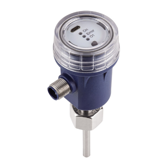
Anzeige- und Bedienelemente 7 Anzeige- und Bedienelemente Anzeige Micro-USB-Schnittstelle Taster LEDs Schutzdeckel mit Sichtfenster (IP67) On: grüne LED Error: rote LED O1: gelbe LED... -
Seite 26: Bedienelemente
7 Anzeige- und Bedienelemente Bedienelemente HINWEIS! Taster und Micro-USB-Schnittstelle des Strömungssensors sind ohne Werkzeug zugänglich. 1. Schutzdeckel (1) abschrauben. 2. Micro-USB-Schnittstelle (2) oder Taster (3) benutzen. -
Seite 27: Funktionsbeschreibung Led-Anzeige
7 Anzeige- und Bedienelemente 7.2.1 Funktionsbeschreibung LED-Anzeige Option Analogausgang LED 1 – grün LED 2 – rot LED 3 – gelb Beschreibung Status Gerät Fehler Schaltausgang Gerät nicht aktiv, keine Spannungsversorgung angeschlossen Gerät aktiv, Messung läuft, Analogausgang aktiv Gerät aktiv, Messung aufgrund eines Fehlers gestoppt Fehlerursache: •... - Seite 28 7 Anzeige- und Bedienelemente...
-
Seite 29: Technische Daten
Technische Daten 8 Technische Daten Einsatz in flüssigen Medien Spannungsversorgung DC 24 V ±10 %, SELV Analogausgang 20 bis 0 mA bzw. 20 bis 4 mA, 0 bis 20 mA bzw. 4 bis 20 mA 800 Ω max. Bürde am Analogausgang Leistungsaufnahme <... -
Seite 30: Ausgang
±0,2 %/K vom Messbereichsendwert Ansprechzeit 4 bis 10 s auf Strömungsänderung Referenzbedingungen Messstoff Wasser Fließgeschwindigkeit ≤ 150 cm/s Mediumstemperatur 20 °C ±5 °C Umgebungstemperatur 20 °C ±5 °C Einbaulage JUMO-Einbauarmatur vertikales Steigrohr Verdrehung ±20 % gegenüber Vorzugsrichtung (Ein- und Auslaufstrecke gemäß Betriebsanleitung) -
Seite 31: Elektrische Daten
8 Technische Daten Elektrische Daten Spannungsversorgung DC 24 V ±10 %, SELV Anforderung Das Gerät muss mit einem Stromkreis versorgt werden, der den Anforderungen an „Energiebegrenzte Stromkreise“ der EN 61010-1 genügt. nach DIN EN 61326-1 Störaussendung Klasse A – nur für den industriellen Einsatz Störfestigkeit Industrieanforderung Stromaufnahme... -
Seite 32: Gehäuse Und Umgebungsbedingungen
8 Technische Daten Gehäuse und Umgebungsbedingungen Gehäuse PA66-GF30 mediumsberührende Teile Edelstahl 316L, 316Ti (1.4404, 1.4571), Dichtungsmaterial FPM Viton Nenndruck (Eingang) PN 75 Berstdruck (Eingang) 200 bar Gewicht ca. 100 g (abhängig von der Fühlerlänge) Umgebungstemperaturbereich -25 bis +70 °C am Gehäuse Mediumstemperaturbereich -25 bis +90 °C (Flüssigkeiten, keine abrasiven Medien) -
Seite 33: Inbetriebnahme
Inbetriebnahme 9 Inbetriebnahme Gerätefunktionsbeschreibung In der folgenden Funktionsbeschreibung (Schaltausgang-Variante) bedeutet das Schließen des Kontak- tes, dass am Schaltausgang die Betriebsspannung anliegt. Beim Öffnen des Kontaktes wird der Schaltausgang hochohmig. Öffner (3) [cm/s] Rückschaltpunkt Schaltpunkt Strömungsgeschwindigkeit Die Öffner-Funktion im Durchfluss (3) öffnet den Kontakt, sobald der Schaltpunkt (2) erreicht wird und schließt den Kontakt wieder, sobald der Rückschaltpunkt (1) erreicht wird. -
Seite 34: Fensteröffner
9 Inbetriebnahme Fensteröffner (3) [cm/s] Rückschaltpunkt Schaltpunkt Strömungsgeschwindigkeit Hysterese Die Fensteröffner-Funktion kann über drei Parameter eingestellt werden. Über den Schaltpunkt und den Rückschaltpunkt werden die prinzipiellen Schaltpunkte definiert. Eine Hysterese kann zusätzlich für Schaltpunkt und Rückschaltpunkt eingestellt werden. Die Hysteresefunktion wird deaktiviert, sobald der Hystereseparameter >= (Sp - Rsp)/2 konfiguriert ist. -
Seite 35: Abgleich Vor Ort
9 Inbetriebnahme Abgleich vor Ort 9.6.1 Anzeige und Bedienung Anzeige und Bedienung 1. Normalzustand Error (1) Grüne LED (1) leuchtet dauerhaft (2) Rote LED (2) aus (3) Gelbe LED (3) leuchtet je nach Zustand (4) Taster (4) nicht gedrückt Strömung einstellen. Teach-In-Funktion Schaltpunkt für alle Flüssigkeiten setzen. -
Seite 36: Normalzustand
9 Inbetriebnahme Normalzustand (1) LED Grün, leuchtet dauerhaft LED Rot, aus LED Gelb, leuchtet je nach Zustand Taster nicht gedrückt Soll-Strömung einstellen Teach-In-Funktion Taster (4) drücken/halten LED (1) Grün, LED (1) Grün dauerhaft an dauerhaft an Taster (4) loslassen LED (1) Grün, blinkt Taster (4) drücken/halten Alle LEDs aus Strömung / Messung... -
Seite 37: High-Level-Funktion
9 Inbetriebnahme Normalzustand (1) LED Grün, leuchtet dauerhaft LED Rot, aus LED Gelb, leuchtet je nach Zustand Taster nicht gedrückt High-Level-Funktion Soll-Strömung einstellen Taster (4) drücken/halten LED (3) Gelb, LED (3) Gelb dauerhaft an dauerhaft an Taster (4) loslassen LED (3) Gelb, blinkt Taster (4) drücken/halten Alle LEDs aus Strömung / Messung... -
Seite 38: Low-Level-Funktion
9 Inbetriebnahme Normalzustand (1) LED Grün, leuchtet dauerhaft LED Rot, aus LED Gelb, leuchtet je nach Zustand Taster nicht gedrückt Soll-Strömung einstellen Low-Level-Funktion Taster (4) drücken/halten LED (1) Grün + LED (1) Grün + LED (3) Gelb LED (3) Gelb, dauerhaft an dauerhaft an Taster (4) loslassen... -
Seite 39: Einschaltverzögerung
9 Inbetriebnahme Teach-In-Funktion Der Rückschaltpunkt wird automatisch um die gleiche Differenz wie der Schaltpunkt verschoben. neuer Rückschaltpunkt = alter Rückschaltpunkt + (aktuelle Strömung - alter Schaltpunkt) Liegt der aktuelle Durchflusswert außerhalb des gültigen Bereiches, wird die Teach-In-Funktion nicht ausgeführt. Einschaltverzögerung (3) [ms] Rückschaltpunkt Schaltpunkt... -
Seite 40: Verhalten Des Schalt- Bzw. Analog-Ausgangs Im Fehlerfall
9 Inbetriebnahme 9.10 Verhalten des Schalt- bzw. Analog-Ausgangs im Fehlerfall Bei Erkennung eines Fehlers wird der Schaltausgang je nach Konfiguration aus- bzw. eingeschaltet. Das Leuchten der roten LED-Anzeige (Error) signalisiert den Fehlerzustand. Der Schaltausgang verfügt über eine Fehlererkennung bzgl. Übertemperatur, Überstrom und Kurz- schluss. -
Seite 41: Wartung
Wartung 10 Wartung HINWEIS! Der Strömungssensor ist weitgehend wartungsfrei. HINWEIS! Folgende Punkte sind regelmäßig zu beachten: • Schutzhülse auf Ablagerungen überprüfen • mit einem weichen Tuch reinigen • Ablagerungen mit einem geeigneten Reiniger (nicht aggressiv) entfernen... - Seite 42 10 Wartung...
- Seite 44 11 China RoHS...
- Seite 46 JUMO GmbH & Co. KG Moritz-Juchheim-Straße 1 Technischer Support Deutschland: 36039 Fulda, Germany Telefon: +49 661 6003-715 Telefon: +49 661 6003-9135 Telefax: +49 661 6003-606 Telefax: +49 661 6003-881899 E-Mail: mail@jumo.net E-Mail: service@jumo.net Internet: www.jumo.net Lieferadresse: Mackenrodtstraße 14 36039 Fulda, Germany...
- Seite 47 JUMO PINOS L02 Calorimetric flow sensor Operating Manual 40604100T90Z000K000 EN/00691112...