Herunterladen Diese Seite drucken
Pentair DigiTrace MiniTrace RMC Montageanweisung

Pentair DigiTrace MiniTrace RMC Montageanweisung

Begleitheizungssteuerungsmodul

Werbung

Verfügbare Sprachen

Verfügbare Sprachen

MoniTrace RMC
Remote module foR ContRol
Installation Instructions
module de Régulation à distanCe
Instructions d'installation
exteRnes BegleitheizungssteueRungsmodul
Montage-Anweisung
Thermal managemenT soluTions
ML-DigiTraceRMC-IM-INSTALL079 R2

Werbung

loading

Inhaltszusammenfassung für Pentair DigiTrace MiniTrace RMC

  • Seite 1 MoniTrace RMC Remote module foR ContRol Installation Instructions module de Régulation à distanCe Instructions d’installation exteRnes BegleitheizungssteueRungsmodul Montage-Anweisung Thermal managemenT soluTions ML-DigiTraceRMC-IM-INSTALL079 R2...
  • Seite 2 Relative humidity Max. 95%, non condensing reference Documents Supply voltage 24 Vdc • MoniTrace 200N v.2 Installation Manual (Pentair Thermal Management reference INSTALL-084) Supply current < 2 A • MoniTrace 200N v.2 Operation Manual Relay output type Mechanical, normally open, non-floating...
  • Seite 3 200n system layout 200N The 200N system controls up to 130 circuits of heat-tracing. RMM2 (remote monitoring module) units collect temperature inputs, and RMC (remote module for control) units switch power contactors on and off. RMM2s and RMCs are connected to the 200N central control and monitoring unit via a single RMM2 RS-485 network...
  • Seite 4 overview of installation procedures for rmC Mount DIN rail in enclosure selected for the application. Install RMC assembly on DIN rail. Connect power, digital input, and contactor coil wiring. Connect RS-485 cables and set address. Update the 200N network. a. mount Din rail The RMC modules installs on a DIN 35 rail in the electrical enclosure or panel.
  • Seite 5 B. install rmC assembly attach the rmC components to the Din rail The RMC-BASE comes assembled. Disassemble the various modules before attaching to DIN rail. Leave space on the left side of the DIN rail for the network connection module and power supply. Clip the Network Processor to the DIN rail at the desired location.
  • Seite 6 Voltage Supply Module large enough to Supply Module must be added to the Connect ground to the Supply Module as carry the current of all contactor coils RMC assembly. Contact Pentair Thermal shown. energized simultaneously. Management for assistance. Install a ground jumper between the...
  • Seite 7 Connect wiring to contactor coils. Connect the contactor coils to the terminals on each RMC-2RO 2-channel relay output modules as shown. note: For large contactors (greater than 80 A rating) connect R-C surge Contactor 1 Contactor 2 suppressors (available as accessories from the contactor supplier) across the coil contacts to reduce large voltage spikes which occur when contactor coils...
  • Seite 8 D. Connect rs-485 cables and set address select the rs-485 address for the rmC unit. Each RMC connected to a 200N Control To ensure you assign an unique address note: RMM2 remote monitoring and monitoring unit must have a unique to each RMC unit, review the system modules are connected on the same address;...
  • Seite 9 e. update the 200n network RMC units are controlled by a central 200N control and monitoring unit. The Update Network Function in the 200N software must be triggered in order for the 200N to recognize new or changed RMC units. Until this software function is run, the 200N will not control new RMC units.
  • Seite 10 moniTrace rmC moDule De rÉgulaTion à DisTanCe insTruCTions D’insTallaTion Description Module RMC-BASE Le module de régulation à distance (RMC) est un ensemble de relais (avec quatre modules servant à la mise sous et hors tension des circuits de traçage pilotés RMC-2RO non enfichés) par la centrale de régulation et de surveillance 200N.
  • Seite 11 schéma du système 200n 200N Le système 200N peut piloter jusqu’à 130 circuits de traçage. Les modules RMM2 (module de surveillance à distance) assurent l’acquisition des données de température et les modules de régulation à distance RMC mettent sous et hors tension les contacteurs RMM2 d’alimentation électrique.
  • Seite 12 marche à suivre pour l’installation du module rmC Monter le rail DIN dans l’armoire électrique. Installer le système RMC sur le rail DIN. Assurer les connexions (alimentation électrique, entrées numériques et contacteurs). Raccorder les câbles RS-485 et programmer les adresses. Mettre à...
  • Seite 13 B. installation du système rmC mise en place des composants du système sur le rail Din Le module RMC-BASE est fourni assemblé. Ses différents éléments doivent être séparés avant installation sur le rail DIN. Prévoir un espace suffisant du côté gauche du rail pour le montage du module de connexion réseau et de l’alimentation électrique.
  • Seite 14 à choisir un calibre de fil supportant contacteur supplémentaire doit être ajouté illustration). l’intensité produite par la mise sous au système RMC (consulter Pentair Thermal Raccorder la terre du secteur au tension simultanée de toutes les Management). module d’alimentation des bobines de bobines de contacteurs.
  • Seite 15 Connexion des bobines de contacteur Relier les bobines des contacteurs aux bornes de chaque relais RMC-2RO à 2 sorties (cf. illustration). remarque : dans le cas de gros Contacteur 1 Contacteur 2 contacteurs (plus de 80 A), installer un limiteur de surtension R-C (à demander au fournisseur des contacteurs) entre Bobines de les bobines de manière à...
  • Seite 16 D. Connexion des câbles rs-485 et adressage Choix de l’adresse rs-485 du module rmC. À chaque module RMC raccordé Étudier le schéma du système pour remarque : les modules de surveillance sur une centrale de régulation et de s’assurer que chaque module RMC à...
  • Seite 17 e. mise à jour du réseau 200n Les modules RMC sont pilotés de manière centralisée par une centrale de régulation et de contrôle 200N. Il convient donc d’activer la fonction de mise à jour réseau du logiciel 200N afin que la centrale 200N soit en mesure de piloter le réseau dans sa nouvelle configuration.
  • Seite 18: Spezifikationen

    (RMC-2RO) nicht potentialfrei Betriebsanleitungen Relais-Ausg.-Nennleistung 230 Vac, 30 Vdc, max. 2 A. • MoniTrace-200N V. 2 Montagehandbuch (Pentair Thermal Management Referenz INSTALL-084) Typ digitaler Eingang Halbleiterrelais, 24 Vdc intern • MoniTrace-200N V. 2 Betriebshandbuch versorgt (Pentair Thermal Management Referenz INSTALL-065)
  • Seite 19 200n systemaufbau Das 200N steuert/regelt bis zu 130 Heizkreise. Über das RMM2 werden die Temperaturwerte erfaßt und das RMC steuert die Heizkreise an. Die Module 200N RMM2 und - RMC kommunizieren über ein RS-485-Netzwerk mit dem elektronischen Steuerungs- und Überwachungsgerät 200N. RMM2 RS-485-Netzwerk MoniTrace RMC...
  • Seite 20 rmC-montageschritte DIN-Schiene in das für die Anwendung ausgewählte Gehäuse montieren. RMC auf DIN-Schiene montieren. Spannungsversorgung, Leistungsschützspulen und digitale Eingänge anschließen. D. RS-485-Kabel anschließen und Adresse einstellen. 200N-Netzwerk aktualisieren. a. Din-schiene montieren Die RMC-Module werden auf einer DIN 35-Schiene in einem Gehäuse oder im Schaltschrank befestigt. montageort Das RMC sollte im selben Schaltschrank oder Gehäuse montiert werden wie die...
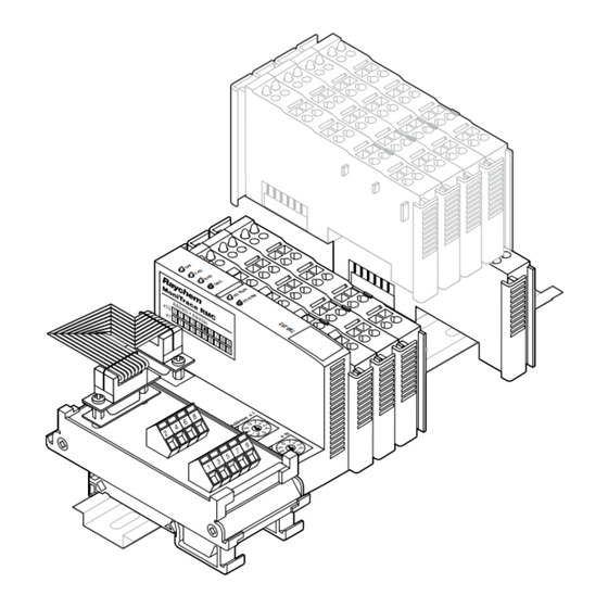
  • Seite 21 B. montage der Baugruppe rmC rmC auf Din-schiene installieren Die Baugruppe RMC-ASE wird vormontiert geliefert. Trennen Sie die einzelnen Komponenten voneinander. Lassen Sie auf der linken Seite der DIN-Schiene ausreichend Platz für das RS-485-Netzwerk-Anschlußmodul und die 24 V DC Spannungsversorgung RMC- PS24 (optional). Installieren Sie den Modbuskoppler an der gewünschten Stelle auf der DIN- Schiene.
  • Seite 22 Sollten Sie technische an das Einspeisemodul anschließen. oder getrennt anschließen. Verwenden Unterstützung benötigen, so wenden Erdung am Einspeisemodul Sie Adern mit ausreichendem Sie sich bitte an Pentair Thermal anschließen. Leiterquerschnitt. Dieser ist abhängig Management. von der Anzahl der Leistungsschütze Elektrische Verbindung (Erdung) und der Summe der Spulenströme aller...
  • Seite 23 leistungsschützspulen anschließen Schließen Sie die Leistungsschützspulen wie dargestellt an die Ausgänge der 2-Kanal-Relais-Ausgangsmodule (RMC-2RO) an. Leistungsschütz 1 Leistungsschütz 2 hinweis: Bei Leistungsschützen mit mehr als 80 A Nennstrom müssen RC-Glieder (Zubehör vom Leistungsschützhersteller) zur Leistungsschützspule Überspannungsbegrenzung verwendet werden. V IN 15 16 –...
  • Seite 24 D. rs-485-Kabel anschließen und adresse konfigurieren rs-485-adresse für das rmC bestimmen Jedem RMC, das an ein MoniTrace Um sicherzustellen, daß man jedem hinweis: Die RMM2 sind am gleichen 200N angeschlossen ist, muß eine RMC eine eindeutige Adresse zuordnet, RS-485-Netzwerk angeschlossen, eindeutige Adresse zugewiesen werden.
  • Seite 25 e. 200n aktualisieren Alle RMC werden von der 200N überwacht und gesteuert. Damit das 200N neue RMC oder Adressenänderungen erkennen kann, muß eine Aktualisierung der Software im 200N vorgenommen werden. Nur dann ist eine einwandfreie Funktion der Module gewährleistet. spannungsversorgung zu allen an das netzwerk angeschlossenen rmC einschalten Überprüfen Sie, ob alle erforderlichen...
  • Seite 28 Fax +48 22 331 29 51 Fax 0800 968624 salesfr@pentair.com salespl@pentair.com salesthermaluk@pentair.com www.thermal.pentair.com All Pentair trademarks and logos are owned by Pentair or its global affiliates. Pentair reserves the right to change specifications without prior notice. © 2013 Pentair. Thermal managemenT soluTions ML-DigiTraceRMC-IM-INSTALL079 R2...