Herunterladen Inhalt Inhalt Diese Seite drucken
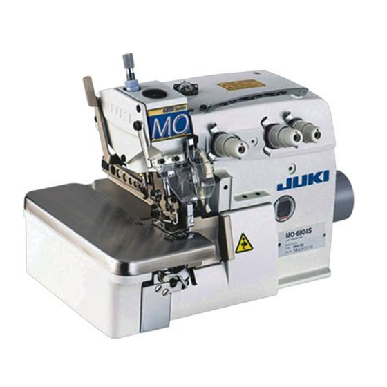
JUKI MO-6804S Betriebsanleitung
Vorschau ausblenden Andere Handbücher für MO-6804S:
Inhaltsverzeichnis

Werbung

Verfügbare Sprachen
  • DE

Verfügbare Sprachen

  • DEUTSCH, seite 78
MO-6804S, MO-6814S,
MO-6816S
取扱説明書
INSTRUCTION MANUAL BETRIEBSANLEITUNG
MANUEL D'UTILISATION MANUAL DE INSTRUCCIONES
MANUALE D'ISTRUZIONI 使用说明书
KULLANMA KILAVUZU
注意:
このたびは、当社の製品をお買い上げいただきまして、ありがとうございました。
安全に使用していただくために、使用前に必ずこの取扱説明書をお読みください。
また、いつでもすぐに読めるように、この取扱説明書を保管してください。
NOTE :
Congratulations on your purchase of a JUKI sewing machine.
Read safety instructions carefully and understand them before using.
Retain this Instruction Manual for future reference.
HINWEIS :
Herzlichen Glückwunsch zu Ihrem Kauf einer JUKI-Nähmaschine.
Lesen Sie die Sicherheitsanweisungen aufmerksam durch, um sich mit ihnen vertraut
zu machen, bevor Sie diese Maschine in Betrieb nehmen. Bewahren Sie diese
Bedienungsanleitung für spätere Bezugnahme auf.
NOTE :
Félicitations pour votre achat d'une machine à coudre JUKI.
Avant d'utiliser la machine, lire attentivement toutes les consignes de sécurité.
Conserver ce manuel pour pouvior le consulter en cas de besoin.
NOTA :
Nuestro agradecimiento y felicitaciones por su compra de esta máquina de coser JUKI.
Antes de comenzar a usar esta máquina lea con detención hasta comprender todas las
instrucciones de sequridad. Conserve este Manual de instrucciones a mano para futuras
consultas.
NOTA :
Congratulazioni per l'acquisto di una macchina per cucire JUKI.
Leggere attentamente e compredere tutte le istruzioni per la sicurezza prima di inziare l' uso
di questa macchina. Conservare questo Manuale d'Instruzioni per pronto riferimento.
注意 :
为了安全地使用,请您在使用之前一定阅读本使用说明书。
另外,请您注意保管本使用说明书,以便随时查阅。
NOT :
Bir JUKI diki makinesi sat n ald
Güvenlik talimat n dikkatle okuyun ve makineyi kullanmadan nce tümüyle
Gelecekte de yararlanmak i in, bu kullanma k lavuzunu muhafaza edin.
n z i in tebrik ederiz.
renin.
No.03
40159379

Werbung

Inhaltsverzeichnis
loading

Inhaltszusammenfassung für JUKI MO-6804S

  • Seite 1 Conserver ce manuel pour pouvior le consulter en cas de besoin. NOTA : Nuestro agradecimiento y felicitaciones por su compra de esta máquina de coser JUKI. Antes de comenzar a usar esta máquina lea con detención hasta comprender todas las instrucciones de sequridad.
  • Seite 4 安全にご使用していただくために ミシン,自動機,付帯装置 ( 以下機械と言う ) は、縫製作業上やむをえず機械の可動部品の近くで作業する ため、可動部品に接触してしまう可能性が常に存在していますので、実際にご使用されるオペレータの方、 および保守,修理などをされる保全の方は、事前に以下の 安全についての注意事項 を熟読されて、十分 理解された上でご使用ください。この 安全についての注意事項 に書かれている内容は、お客様が購入さ れた商品の仕様には含まれない項目も記載されています。 なお、取扱説明書および製品の警告ラベルを十分理解していただくために、警告表示を以下のように使い分 けております。これらの内容を十分に理解し、指示を守ってください。 ( I ) 危険の水準の説明 機械操作時,保守時,当事者,第 3 者が取り扱いを誤ったり、その状況を回避しな 危険 い場合、死亡または重傷を招く差し迫った危険のあるところ。 機械操作時,保守時,当事者,第 3 者が取り扱いを誤ったり、その状況を回避しな 警告 い場合、死亡または重傷を招く潜在的可能性のあるところ。 機械操作時,保守時,当事者,第 3 者が取り扱いを誤ったり、その状況を回避しな 注意 い場合、中・軽傷害を招く恐れのあるところ。 (II) 警告絵表示および表示ラベルの説明 運動部に触れて、怪我をする恐れ 作業時にミシンを持つと、手を があります。 怪我する恐れがあります。...
  • Seite 5 安全についての注意事項 事故とは: 人身並びに財産 に損害を与える ことをいう。 危険 1. 感電事故防止のため、電装ボックスを開ける必要のある場合は、電源を切り、念のため 5 分以上経 過してから蓋を開けてください。 注意 基本的注意事項 1. ご使用される前に、取扱説明書および付属に入っている全ての説明書類を必ずお読みください。 また、いつでもすぐに読めるように、この取扱説明書を大切に保存してください。 2. 本項に書かれている内容は、購入された機械の仕様に含まれていない項目も記載されています。 3. 針折れによる事故防止のため、安全眼鏡を着用してください。 4. 心臓用ペースメーカーをお使いの方は、専門医師とよくご相談のうえお使いください。 安全装置・警告ラベル 1. 安全装置の欠落による事故防止のため、この機械を操作する際は、安全装置が所定の位置に正しく 取り付けられ、正常に機能することを確認してから操作してください。安全装置については、 「安全 装置と警告ラベルについて」の頁を参照してください。 2. 人身事故防止のため、安全装置を外した場合は、必ず元の位置に取り付け、正常に機能することを 確認してください。 3. 人身事故防止のため、機械に貼り付けてある警告ラベルは、常にはっきり見えるようにしておいて ください。剥がれたり汚損した場合、新しいラベルと交換してください。 用途・改造 1. 人身事故防止のため、この機械は、本来の用途および取扱説明書に規定された使用方法以外には使 用しないでください。用途以外の使用に対しては、当社は責任を負いません。 2. 人身事故防止のため、 機械には改造などを加えないでください。 改造によって起きた事故に対しては、 当社は責任を負いません。...
  • Seite 6 各使用段階における注意事項 運  搬 1. 人身事故防止のため、機械の持ち上げ,移動は、機械質量を踏まえ安全を確保した方法で行ってく ださい。なお機械質量については、取扱説明書本文をご確認ください。 2. 人身事故防止のため、持ち上げ,移動の際は、転倒,落下などを起こさないよう十分安全策をとっ てください。 3. 予期せぬ事故や落下事故、機械の破損防止のため、開梱した機械を再梱包して運搬することはおや めください。 開  梱 1. 人身事故防止のため、開梱は上から順序よく行ってください。木枠梱包の場合は、特に釘には十分 注意してください。また、釘は板から抜き取ってください。 2. 人身事故防止のため、機械は重心位置を確かめて、慎重に取り出してください。 据え付け ( I) テーブル,脚 1. 人身事故防止のため、テーブル,脚は純正部品を使用してください。やむをえず非純正部品を使用 する場合は、機械の重量,運転時の反力に十分耐え得るテーブル,脚を使用してください。 2. 人身事故防止のため、脚にキャスターを付ける場合は、十分な強度をもったロック付きキャスター を使用し、機械の操作中や保守,点検,修理の時に機械が動かないようにロックしてください。 (II)ケーブル,配線 1. 感電,漏電,火災事故防止のため、ケーブルは使用中無理な力が加わらないようにしてください。 また、V ベルトなどの運転部近くにケーブル配線する時は、30mm 以上の間隔をとって配線してく ださい。 2. 感電,漏電,火災事故防止のため、タコ足配線はしないでください。 3. 感電,漏電,火災事故防止のため、コネクタは確実に固定してください。 また、コネクタを抜く時は、コネクタ部を持って抜いてください。 (III)接地 1.
  • Seite 7 6. サーボモーターをご使用の場合は、機械停止中はモーター音がしません。不意の起動による事故防 止のため、電源の切り忘れに注意してください。 7. 過熱による火災事故を防ぐため、モーター電源ボックスの冷却口をふさいで使用することはやめて ください。 給  油 1. 機械の給油箇所には、JUKI 純正オイル,JUKI 純正グリースを使用してください。 2. 炎症,カブレを防ぐため、目や身体に油が付着した時は、直ちに洗浄してください。 3. 下痢,嘔吐を防ぐため、誤って飲み込んだ場合は、直ちに医師の診断を受けてください。 保  守 1. 不慣れによる事故防止のため、修理,調整は機械を熟知した保全技術者が取扱説明書の指示範囲で 行ってください。また、部品交換の際は、当社純正部品を使ってください。不適切な修理,調整お よび非純正部品使用による事故に対しては、当社は責任を負いません。 2. 不慣れによる事故や感電事故防止のため、電気関係の修理,保全 ( 含む配線 ) は、電気の専門知識 の有る人、または当社,販売店の技術者に依頼してください。 3. 不意の起動による事故防止のため、エアーシリンダーなどの空気圧を使用している機械の修理や保 全を行う時は、空気の供給源のパイプを外し、残留している空気を放出してから行ってください。 4. 人身事故防止のため、修理調整,部品交換などの作業後は、ねじ,ナットなどがゆるんでいないこ とを確認してください。 5. 機械の使用期間中は、定期的に清掃を行ってください。この際、不意の起動による事故防止のため、 必ず電源を切り、ミシンおよびモーターが完全に停止したことを確認してから行ってください。 6. 保守,点検,修理の作業の時は、必ず電源を切り、ミシンおよびモーターが完全に停止したことを 確認してから行ってください。 (クラッチモーターの場合、電源を切った後もモーターは惰性でしば...
  • Seite 8 MO-6800S シリーズをより安全にお使いいただくための注意事項 1. 感電による事故防止ため、電源を入れたままでモーター電装ボックスのふたを開けたり、 電装ボックス内の部品に触れないでください。 危険 1. 人身事故防止のため、ベルトカバー、目保護カバー等安全装置は外した状態で運転しない でください。 2. 巻き込みによる人身事故防止のため、モータープーリーカバー付きのモーターを使用してく 注意 ださい。 3. 感電による事故防止のため、 電源アース線を外した状態でミシンを運転しないでください。 4. 巻き込みによる人身事故防止のため、ミシン運転中ははずみ車、V ベルト、モーター付近 に指、頭髪、衣類を近づけたり、物を置かないでください。 5. 人身事故防止のため、電源を入れる時、またミシン運転中は布切りメスおよび針の付近に 指を入れないでください。 6. 人身事故防止のため、ミシン運転中に目保護カバー内に指を入れないでください。 7. 感電・漏電、火災事故防止のため、電源プラグ挿抜の際は、事前に電源を切り、コードで はなく電源プラグを持って挿抜してください。 8. 不意の起動による人身事故防止のため、 本機から離れる場合は、 必ず電源を切ってください。 9. 不意の起動による人身事故防止のため、停電した時は、必ず電源を切ってください。 10. 不意の起動による人身事故防止のため、ベルトカバー、モータープーリーカバーおよび、 V ベルトを外す時は電源を切って、起動ペダルを踏んでもミシンが動かないことを確かめ てから外してください。 11. 不意の起動による人身事故防止のため、ミシンの点検や調整、掃除、糸通し、針の交換等 をする時は、必ず電源を切って、起動ペダルを踏んでもミシンが動かないことを確かめて...
  • Seite 9 ミシン運転前のご注意 注意 機械の誤動作や損傷をさけるために、次の項目を確認してください。 • この説明書の内容を読んで十分に理解してください。 • 主要部分の機能を知って、注意事項を理解してください。 • 警告ラベルの内容を十分に理解してください。 • このミシンの操作方法を理解して慣れるようにしてください。 • オペレーターは、良好な精神状態を保つようにしてください。 • オペレーターは、適切な衣服、適正な作業着を着用してください。 • 必要に応じて、ミシンの操作方法に徐々に精通させるようにしてください。 安全装置と警告ラベルについて ここに記載されている機械および安全装置はあくまで、日本国内仕様として製造された機種およびそれに装 着・同梱された安全装置であり、仕向地、仕様により異なる場合もあります。 目保護カバー 指ガード 警告ラベル (i 頁警 針折れ等部品の飛散による目、顔 指と針との接触を防止 ミシン操作時の 告ラベ するカバーです。 等のけがを防止するカバーです。 最低限の注意が ル参照 ) 記載されてます。 ベルトカバー V ベルトによる手、頭髪、 衣類への巻き込みを防止す るカバーです。 布台、布台カバー...
  • Seite 10: Inhaltsverzeichnis

    目 次 1. 仕 様 ............................1 2. 主要部品名称 .........................2 3. 設置 ............................3 4. 注油と排油 ..........................6 5. 糸通し ............................8 6. 糸調子の調整 ........................11 7. 針の交換 ..........................12 8. 縫い目長さの調整 ......................13 9. 差動比の調整 ........................13 10. メスの交換 .........................14 11. かがり幅の調整 .........................15 12. 針の高さの調整 .........................15 13. 押えの調整 .........................16 14.
  • Seite 11: 仕 様

    伸し縫い 1 : 0.7 (最大 1 : 0.6) / 60H 1 : 0.9 使用針 DC × 27(標準) 押え上昇量 5 ∼ 7 mm 使用油 JUKI MACHINE OIL #18 重量 27kg JIS B 9064 に準拠した測定方法による「騒音レベル」 騒音 縫い速度 6,500 sti/min : 騒音レベル≦ 83.0dBA ( ※ 1 定常運転時 ) ※...
  • Seite 12: 主要部品名称

    2. 主要部品名称 ❶ 押え引き上げレバー ❷ 押え ( 組 ) ❸ 糸立て装置 ❹ オイルゲージ ❺ プーリー ❸ ❻ 布台カバー ❶ ❺ ❹ ❷ ❻ – 2 –...
  • Seite 13 3. 設置 ・ ミシンの設置は、資格を持つ技術者だけが行ってください。 ・ 必要な電気工事については、販売店または資格を持つ電気技師に連絡してください。 ・ ミシン重量は 27 kg です。設置は 2 人以上で行ってください。 ・ 設置が完了するまでは電源コードを接続しないでください。誤ってペダルを踏んだ場合に 警告 ミシンが作動し、怪我をする場合があります。 ・ ミシン頭部を傾けたり元の位置に戻したりするときは、両手で頭部を持ってください。片 手で持たないでください。 ・ ミシンの不意の起動による人身の損傷を防ぐため、電源を切り、モーターの回転が止まっ たことを確認してから行ってください。 開梱後、ミシンを移動させる際に、布台 カバー❶の下部を持たないでください。 ❶ 1) テーブル図とパーツリストを参照して、フ レーム受け板❷に、送風ケース❸、防振ゴム ❹を順序どおり組み付けてください。 ❹ ❸ ❷ – 3 –...
  • Seite 14 2) 布くずシュートセットと糸立てを組み付けてください。 ❻ ❺ 3) モーター始動ペダル❺を左側に組み付け、押え上げペダル❻を右側に組み付けてください。 – 4 –...
  • Seite 15 4) ミシンの回転方向は、プーリー側から見て時 計方向であることを確認してください。 絶対に逆回転させないでください。 給油ポンプが働かなくなり、焼き付きの ❼ 原因となります。 モーターベルト❼の最適な張力は、ベルトを 指で 10 mm 押せる張力です。 プーリー❽のサイズおよび縫い速度について 10 mm は、下の表を参照してください。 ( 卓上式、全沈式とも同じです。) ❽ 5) 作業後は、ベルトカバー❾をねじでしっかり と固定してください。 ❾ モータープーリー直径(mm)/ V ベルト ( インチ ) 縫い速度 (sti/min) 60 Hz 50 Hz 4,500 70 / 33 85 / 33 5,000 80 / 33 95 / 34...
  • Seite 16: 注油と排油

    4. 注油と排油 警告 ミシンの不意の起動による人身の損傷を防ぐため、電源を切り、モーターの回転が止まったこ とを確認してから行ってください。 (1) 潤滑油の注油 ❶ ❸ ❷ 1) 油窓❶を外し、付属の超高速潤滑油(JUKI MACHINE OIL #18)もしくは同等のものを注油し てください。オイルゲージが 2 本の指示線の間に来たら、油窓❶を締めます。 2) 新しいミシンまたは長期間使用しなかったミシンの運転を始める前に、針棒❷、上ルーパーガイ ド部❸の斜線部に注油してください。 (2) 排油および油の交換 1) ねじ❶をゆるめ、オイルタンク内のオイルを すべて排出します。次に、再びねじ❶を締め ます。 2) 使用期間を延ばすためには、最初の 4 週間経 過後にオイルを交換し、その後は 4 か月毎に オイルの交換を行ってください。 ❶ – 6 –...
  • Seite 17 3) 使用期間を延ばすために、本機はオイルフィ ルタ❷を備えています。毎月このオイルフィ ルタ❷を清掃し、必要に応じて交換してくだ さい。 ❷ 針冷却用潤滑油:シリコンオイル シリコンオイル シリコンオイル – 7 –...
  • Seite 18: 糸通し

    5. 糸通し 警告 糸通しの手順に従ってください。誤った糸通しにより、糸切れ、目飛び、パッカリングなど縫 いトラブルが起こることがあります。 MO-6804S MO-6814S – 8 –...
  • Seite 19 MO-6814S- △△△ -44H MO-6816S – 9 –...
  • Seite 20 MO-6816S- △△△ -50H MO-6816S- △△△ -60H – 10 –...
  • Seite 21: 糸調子の調整

    6. 糸調子の調整 糸調子は、布の種類と厚さ、縫い目長さ、縫い目の幅などに応じて適切に調整してください。また、 その都度、個別に糸調子ナットも調整します。ナットを時計方向に回すと糸調子が強くなり、逆方向 に回すと弱くなります。 (1) 糸調子ナット 1) 糸調子ナット No. ①は、❶の糸を制御します。 2) 糸調子ナット No. ②は、❷の糸を制御します。 3) 糸調子ナット No. ③は、❸の糸を制御します。 4) 糸調子ナット No. ④は、❹の糸を制御します。 5) 糸調子ナット No. ⑤は、❺の糸を制御します。 MO-6804S MO-6816S*** MO-6814S*** ❸ ❸ ❸ ❹ ❹ ❹ ❺ ❷ ❶ ❶...
  • Seite 22: 針の交換

    (3) 下糸カム糸案内調整 1) 下糸の調整が適正でないと、糸 のループが不安定になります (糸 がゆるみすぎるか、 または糸ルー ⊖ プが形成されません) 。 ⊕ 2) ⊕は、縫製時の糸の供給量が増 えることを意味します。 ⊖ 3) ⊖は、縫製時の糸の供給量が減 ⊕ ることを意味します。 7. 針の交換 警告 ミシンの不意の起動による人身の損傷を防ぐため、電源を切り、モーターの回転が止まったこ とを確認してから行ってください。 ❶ 1) DC × 27 の針または同等のものをお使いください。 2) ねじ❶をゆるめ、針を外します。 3) えぐり部が後ろ向きになるようにして新しい針をいっぱいに差し込みます。 4) ねじ❶を締めます。 – 12 –...
  • Seite 23: 縫い目長さの調整

    8. 縫い目長さの調整 警告 ミシンの不意の起動による人身の損傷を防ぐため、電源を切り、モーターの回転が止まったこ とを確認してから行ってください。 縫い目長さは、布地、差動比、またはその他の要因によって変更してください。 ボタン❶を押しながら、 ボタンがロックされるまでプーリーを回します。次に、 希望の縫い目長さになっ たら、ボタンを放します。 ❶ 粗くなる 細かくなる 最大差動比 プーリー目盛り 縫い目長さ(目安) 1.13 1.66 2.19 2.72 3.25 9. 差動比の調整 警告 ミシンの不意の起動による人身の損傷を防ぐため、電源を切り、モーターの回転が止まったこ とを確認してから行ってください。 1) 差動調節ナット❷をゆるめて、差動調節レ バー❶を上へ動かすと伸し縫い、下へ動かす と縮み縫いができます。 ❸ 2) レバー❶を少し動かしたいときは差動送り微 量調節ねじ❸を使います。 ❶ 3) 調節後は確実に差動調節ナット❷を締めてく ださい。 ❷ – 13 –...
  • Seite 24: メスの交換

    10. メスの交換 警告 ミシンの不意の起動による人身の損傷を防ぐため、電源を切り、モーターの回転が止まったこ とを確認してから行ってください。 ❸ ❹ ❶ ❷ (1) 上メスの交換 1) ねじ❶をゆるめ、下メス取付台❷を左に動かします。次に、ねじ❶を少し締めます。 2) ねじ❸を外し、新しい上メスを取り付けます。次に、ねじ❸を少し締めます。 3) プーリーを回して上メスを下死点まで下げます。上メスが下メスと 0.5 ∼ 1.0 mm 程度交差する ように上メスの高さを調整します。調整後、ねじ❸を締めます。 4) ねじ❶をゆるめ、下メス取付台❷を元の位置に戻します。上メスと下メスが、糸を正確に切断で きるかどうか調べます。確認できたら、ねじ❶を締めます。 (2) 下メスの交換 1) ねじ❶をゆるめ、下メス取付台❷を左に動かします。次に、ねじ❶を少し締めます。 2) ねじ❹をゆるめます。下メスを取り出して新しいメスに交換します。 3) 下メスの刃が針板上面に一致するよう、下メスの刃を調整します。調整後、ねじ❹を締めます。 4) ねじ❶をゆるめ、下メス取付台❷を元の位置に戻し、上メスと下メスが、糸を正確に切断できる かどうか調べます。確認できたら、ねじ❶を締めます。 – 14 –...
  • Seite 25: かがり幅の調整

    11. かがり幅の調整 警告 ミシンの不意の起動による人身の損傷を防ぐため、電源を切り、モーターの回転が止まったこ とを確認してから行ってください。 1) プーリーを回して上メス❹を下死点まで下げ ❸ ます。 2) ねじ❶をゆるめ、下メス取付台❷を左に動か ❹ します。次に、ねじ❶を少し締めます。 3) ねじ❸をゆるめ、上メス取付台を、設定した い幅になるまで左または右に動かします。次 に、ねじ❸を締めます。 4) ねじ❶をゆるめ、下メス取付台❷を下メスと 上メスが接触する位置まで動かします。 ❶ 上メス、下メスが糸を切断できるかどうか確 認します。確認後、ねじ❶を締めます。 ❷ 12. 針の高さの調整 警告 ミシンの不意の起動による人身の損傷を防ぐため、電源を切り、モーターの回転が止まったこ とを確認してから行ってください。 プーリーを回して、針を最上位置まで上げたとき の針先から針板上面までの距離を合わせます。 ❷ ❶ 1) ねじ (4 本 ) ❶をゆるめ、上カバー❷を開け て外します。 2) ねじ❸をゆるめ、針棒❹を設定したい高さま...
  • Seite 26: 押えの調整

    13. 押えの調整 (1) 押え位置の調整 強 ❶ 弱 ❷ ❹ ❼ ❺ ❸ ❻ 1) 押えの調節ねじ❶と押えのねじ❼をゆるめます。 2) 押えの溝が針板の溝と一致するように、また、押えの底面が針板に平らに乗るように、押え❻を 動かします。調整後、ねじ❼を締めます。 3) ねじ❺をゆるめ、❸が❷と一致し、❷が上下にスムーズに動くように、❹を左右に動かします。 調整後、ねじ❺を締めます。 4) 適正圧力の調整方法:ねじ❶を時計方向に回すと、圧力が上がります。反時計方向に回すと、圧 力が下がります。 – 16 –...
  • Seite 27 1) プーリーを回して、押えの底面が針板に平らに接触するまで、送り歯を下げます。 2) 押え上げ腕❶と固定ブラケット❷に 1 mm のすき間を空けます。このすき間は、ねじ❸を少しゆ るめて調整することができます。 3) ナット❹をゆるめ、押え上げレバー❻を押して押えを針板から上げます。押え上げ高さは機種に より異なりますので、下記表を参照し機種にあった調整をしてください。 次に、ねじ❺を押え上げレバー❻に接触するように調整してナット❹を締めます。 4) すべての調整が終わったら、ねじ❸を締めてください。 ( 単位 : mm) 機種 押え高さ (A) MO-6804S MO-6814S-2 △ H MO-6814S-3 △ H MO-6814S-4 △ H MO-6814S-30P MO-6816S-3 △ H MO-6816S-50H MO-6816S-60H MO-6816S-30P – 17 –...
  • Seite 28: 送り歯の調整

    14. 送り歯の調整 警告 ミシンの不意の起動による人身の損傷を防ぐため、電源を切り、モーターの回転が止まったこ とを確認してから行ってください。 (1) 送り歯高さの調整 ❷ ❹ ❶ ❸ 1) プーリーを回して送り歯を最上点まで上げます。 2) ねじ❶をゆるめ、主送り歯❷を上下させて歯側が常に針板から 0.9 ∼ 1.1 mm(30P:0.7 ∼ 0.9 mm, 60H:1.0 ∼ 1.2 mm)上に出ているようにします。調整後、ねじ❶を締めます。 3) ねじ❸をゆるめ、 差動送り歯❹を上下させて、 主送り歯❷と同一高さに調節し、 ねじ❸を締めます。 (2) 送り歯の傾き調整 調整を行うには、ねじ❶をゆるめ、後部支 ❶ 持軸❷を回します。送り歯が針板上面に一 致したとき、送り歯が水平(30P:送り歯 が手前下がり)となったところで、ねじ❶ ❷ を締めてください。 30P の場合...
  • Seite 29: 針とルーパーの関係

    15. 針とルーパーの関係 警告 ミシンの不意の起動による人身の損傷を防ぐため、電源を切り、モーターの回転が止まったこ とを確認してから行ってください。 (1) 針と上ルーパーの関係 上ルーパーが最も左の位置まで 移動したとき、ルーパー先端か ら針の中心線との距離は 4.8 ∼ 5.2 mm です。2 本針機種では、 ルーパー先端から左針の中心線 ま で の 距 離 は、5.4 ∼ 5.7 mm (60H:5.0 ∼ 5.5 mm)です。 4.8 ∼ 5.4 ∼ 5.2 mm 5.7 mm (2) 針と下ルーパーの関係 1) 下ルーパーが最も左の位置まで移動...
  • Seite 30 (3) 上ルーパーと下ルーパーの関係 上ルーパーと下ルーパーが交差するとき、両ルー パーは常にできるだけ近づくようにします。上 ルーパーと下ルーパーは、接触せず、ぶつからな いようにしてください。交差時のすき間は 0.05 ∼ 0.2 mm です。 (4) 針と二重環ルーパーの関係 二重環ルーパーが最も左の位置まで移動したと き、二重環ルーパーと針の中心線までの距離は、 1.4 ∼ 1.9 mm(50H, 60H:1.6 ∼ 2.3 mm) となります。 1.4 ∼ 1.9 mm 二重環針❹のえぐり下端頂点 と二重環ルーパー ❺のすき間が 0 ± 0.05 mmとなるように調整し ❹ てください。 ❹ そのとき、二重環ルーパー❺の先端が、二重環針 ❹の側面より内側にあるようにします。 先端が、針側...
  • Seite 31: 二重環ルーパーの運動量の調整

    16. 二重環ルーパーの運動量の調整 警告 ミシンの不意の起動による人身の損傷を防ぐため、電源を切り、モーターの回転が止まったこ とを確認してから行ってください。 二重環ルーパーの動きは、 楕円形です。 二重環ルー パーの前/後の運動量 を調整する必要がある場 合は、次の手順で調整してください。 1) ミシンの背面のカバー❶を開けます。 2) ねじ❸を少しゆるめます。 ❶ ❷ 3) ねじ❷を回して調整します。 運動量を大きくする場合は、ねじを⊕方向に ⊕ ⊖ 回します。 運動量を小さくする場合は、ねじを⊖方向に 回します。 4) 調整後、ねじ❸を締めます。 5) 最後にカバー❶を閉めます。 ❸ – 21 –...
  • Seite 32 17. 保守 1. 清掃を行う前には、必ず電源スイッチを切ってください。不注意によりペダルを踏んでし まうと、ミシンが動作して怪我をすることがあります。 2. 潤滑油やグリースを扱う場合は、目に入ったり皮膚に付いたりしないように、必ず保護メ ガネと手袋を着用してください。これを怠ると、炎症を起こすことがあります。 警告 3. また、オイルやグリースを飲み込むと吐き気や下痢を起こしますので、飲み込まないよう にしてください。オイルは、子供の手の届かない場所に保管してください。 4. ミシン頭部を傾けたり、元の位置に戻したりする場合は、両手で頭部を持ってください。 片手でミシンを動かすと、ミシン頭部の重量によって落としてしまい怪我をする恐れがあ ります。 << 定期保守項目 >> 保守周期 保守項目 1. 送り歯からの糸くずや布くずの除去 2. オイルパンに十分な油があるかの確認(油量は、オイルゲージの上下の赤色マーク 毎日 の間に保つこと) 3. ミシンと操作テーブルを清潔に保つこと 1. 電源コードの外観をきれいに保つこと 2. 操作パネルをきれいに保つこと 毎週 3. 電源部品のゆるみがないかどうかを確認すること、または正しい位置に取り付けて あるかどうかを確認すること 4 か月毎 1. オイルパンの中の油の交換 毎年...
  • Seite 33 18. ルーパー合わせおよび針受け合わせ寸法値 1. 不慣れによる事故防止のため、 調整 ・ 部品交換は、 機械を熟知した保全技術者、 または当社、 警告 販売店の技術者に依頼してください。 2. 起動による人身への損傷を防ぐため、ねじのゆるみ、部品の当たりがないか、確認後ご使 用ください。 表中の寸法は、標準的なルーパー合わせ寸法です。あくまで参考寸法としてください。縫製物、 糸により多少の変更が必要です。 ( 単位 : mm) 機種 0.05 ∼ 0.2 mm MO-6804S 10.4-10.6 (10.8) 4.8-5.2 3.7-3.9 MO-6814S-2 △ H 10.4-10.6 (9.1) (10.5) 5.4-5.7 3.7-3.9 MO-6814S-3 △ H 10.4-10.6...
  • Seite 34: 天びん・下糸カム位置寸法値 ( 標準合わせ )

    19. 天びん・下糸カム位置寸法値 ( 標準合わせ ) 警告 ミシンの不意の起動による人身の損傷を防ぐため、電源を切り、モーターの回転が止まったこ とを確認してから行ってください。 (1) 針糸天びん、針糸案内位置 MO-6804S MO-6814S** MO-6816S** 7.5mm ( 単位 : mm) MO-6814S MO-6816S 30P, 60H を除く 11.5 – 24 –...
  • Seite 35 (2) ルーパー天びん、ルーパー糸案内位置 ( 単位 : mm) 機種 MO-6804S 11.5 17.5 28.5 MO-6814S-2 △ H 21.5 14.5 MO-6814S-3 △ H 21.5 14.5 MO-6814S-4 △ H 21.5 14.5 28.5 MO-6814S-30P 11.5 17.5 28.5 MO-6816S-3 △ H 21.5 17.5 28.5 MO-6816S-50H 33.5 10.5 28.5...
  • Seite 36: テーブル図面

    20. テーブル図面 単位:mm 公差:± 2 1200 断面 断面 – 26 –...
  • Seite 37 テーブル全沈式 ※ 補助テーブル必要 単位:mm 公差:± 2 重量:12.4kg ± 5% オートヘマー装置を 取 り 付 け る 場 合 は、 この部分を取り除く 断面 – 27 –...
  • Seite 38 テーブル全沈式 補助テーブル 単位:mm 公差:± 2 重量:4.25kg ± 5% 断面 断面 – 28 –...
  • Seite 40 TO ENSURE SAFE USE OF YOUR SEWING MACHINE For the sewing machine, automatic machine and ancillary devices (hereinafter collectively referred to as "machine"), it is inevitable to conduct sewing work near moving parts of the machine. This means that there is always a possibility of unintentionally coming in contact with the moving parts.
  • Seite 41: Safety Precautions

    SAFETY PRECAUTIONS DANGER CAUTION...
  • Seite 44 Precautions to be taken so as to use the MO-6800S Series more safely 1. So as to avoid electric shock hazards, do not open the cover of the electrical box of the motor or touch any part inside the electrical box with the power to the machine turned ON. 1.
  • Seite 45 CAUTION In addition, be aware that the safety devices such as the eye protection cover and nger guard are sometimes omitted in the sketches, illustrations and gures included in the Instruction Manual for the explanation's sake. In the practical use, never remove those safety devices. CAUTION BEFORE OPERATION WARNING : To avoid malfunction and damage of the machine, con rm the following.
  • Seite 46 Model MO-6800S Series Description Industrial Sewing Machine Function make stitches and sew Applied harmonized standards, in particular : EN ISO12100, EN ISO10821, EN 50581 Manufacturer : JUKI CORPORATION 2-11-1, Tsurumaki, Tama-shi, Tokyo, Japan...
  • Seite 47 viii...
  • Seite 48 CONTENTS 1. SPECIFICATION ......................1 2. NAMES OF MAJOR PARTS ..................2 3. INSTALLATION ......................3 4. LUBRICATION AND DRAINAGE .................. 6 5. THREADING ........................8 6. ADJUSTING THE THREAD TENSION ................ 11 7. REPLACE THE NEEDLE ..................... 12 8. ADJUSTING THE STITCH LENGTH ................13 9.
  • Seite 49: Specification

    Needle DC × 27 (Standard) Presser foot lift 5 to 7 mm Lubricating oil JUKI MACHINE OIL #18 Weight 27 kg - Equivalent continuous emission sound pressure level (L ) at the workstation: A-weighted value of 83.0 dB; (Includes K = 2.5 dB);...
  • Seite 50: Names Of Major Parts

    2. NAMES OF MAJOR PARTS ❶ Presser foot lifting lever ❷ Presser foot (asm.) ❸ Thread stand ❹ Oil gauge ❺ Pulley ❻ Cloth plate cover ❸ ❶ ❺ ❹ ❷ ❻ – 2 –...
  • Seite 51: Installation

    3. INSTALLATION WARNING : • Machine installation should only be carried out by a quali ed technician. • Contact your dealer or a quali ed electrician for any electrical work that may need to be done. • The sewing machine weighs 27 kg. The installation should be carried out by two or more people. •...
  • Seite 52 2) Assemble the waste disposal set and the thread stand. ❻ ❺ 3) Assemble the motor starting pedal ❺ to the left side, and the presser foot pedal ❻ to the right side. – 4 –...
  • Seite 53 4) The correct direction of rotation of the sewing machine is clockwise. Never allow the machine to rotate in the reverse direction. If the machine rotates counterclockwise, the oil pump will fail to ❼ function resulting in seizure. The best tension of the motor belt ❼ is that the belt to the table shown below for the size of pulley ❽...
  • Seite 54: Lubrication And Drainage

    1) Remove oil sight window ❶ at a super-high speed (JUKI MACHINE OIL #18) supplied with the unit or equivalent through the oil inlet. When the oil surface reaches the space between two marker lines on the oil gauge, tighten oil sight window ❶.
  • Seite 55 3) To extend the usage term, this machine has ❷ ❷ once every month and change it with a new one where necessary. ❷ Needle cooling lubrication oil : SILICON OIL SILICON OIL SILICON OIL – 7 –...
  • Seite 56: Threading

    5. THREADING WARNING : Follow the procedures for threading. Wrong threading can cause stitching troubles such as thread breakage, stitch skipping and puckering. MO-6804S MO-6814S – 8 –...
  • Seite 57 MO-6814S-△△△-44H MO-6816S – 9 –...
  • Seite 58 MO-6816S-△△△-50H MO-6816S-△△△-60H – 10 –...
  • Seite 59: Adjusting The Thread Tension

    2) Tension adjusting nut No. ② controls thread ❷. 3) Tension adjusting nut No. ③ controls thread ❸. 4) Tension adjusting nut No. ④ controls thread ❹. 5) Tension adjusting nut No. ⑤ controls thread ❺. MO-6804S MO-6816S*** MO-6814S*** ❸...
  • Seite 60: Replace The Needle

    (3) Adjusting the looper thread cam thread guide 1) In the case the looper thread is not appropriately adjusted, thread loops cannot be formed with consistency. (Thread can be excessively loosened ⊖ or thread loops cannot be formed.) ⊕ 2) ⊕means to have more thread amount ⊖...
  • Seite 61: Adjusting The Stitch Length

    8. ADJUSTING THE STITCH LENGTH WARNING : To protect against possible personal injury due to abrupt start of the machine, be sure to start the following work after turning the power off and ascertaining that the motor is at rest. Change the stitch length appropriately according to the material to be used, differential feed ratio or other relevant factors.
  • Seite 62: Replace The Knives

    10. REPLACE THE KNIVES WARNING : To protect against possible personal injury due to abrupt start of the machine, be sure to start the following work after turning the power off and ascertaining that the motor is at rest. ❸ ❹...
  • Seite 63: Adjusting The Overedge Width

    11. ADJUSTING THE OVEREDGE WIDTH WARNING : To protect against possible personal injury due to abrupt start of the machine, be sure to start the following work after turning the power off and ascertaining that the motor is at rest. 1) Turn the pulley to move the upper knife ❹...
  • Seite 64: Adjusting The Presser Foot

    13. ADJUSTING THE PRESSER FOOT (1) Adjusting the presser foot position Increase Decrease ❶ ❷ ❹ ❼ ❺ ❸ ❻ 1) Loosen adjusting screw ❶ and screw ❼ of the presser foot. 2) Move the presser foot ❻ so that the groove of the presser foot can align with the groove of the throat plate. ❼.
  • Seite 65 Then, adjust screw ❺ so that it comes in contact with presser foot lifting lever ❻. Tighten nut ❹. 4) After all the adjustments above, please tighten the screw ❸. (Unit : mm) Model Lift amount of the presser foot (A) MO-6804S MO-6814S-2△H MO-6814S-3△H MO-6814S-4△H MO-6814S-30P MO-6816S-3△H...
  • Seite 66: Adjusting The Feed Dog

    14. ADJUSTING THE FEED DOG WARNING : To protect against possible personal injury due to abrupt start of the machine, be sure to start the following work after turning the power off and ascertaining that the motor is at rest. (1) Adjusting the feed dog height ❷...
  • Seite 67: The Relationship Between The Needle And The Looper

    15. THE RELATIONSHIP BETWEEN THE NEEDLE AND THE LOOPER WARNING : To protect against possible personal injury due to abrupt start of the machine, be sure to start the following work after turning the power off and ascertaining that the motor is at rest. (1) The relationship between the needle and the upper looper When the upper looper moves to the leftmost point, the distance...
  • Seite 68 (3) The relationship between the upper looper and the lower looper When the upper and the lower loopers cross, keep them as close as possible. Somehow, the loopers shall not either touch nor collide to each other. The clearance of 0.05 to 0.2 mm should be provided between the upper and lower loopers when they are crossing.
  • Seite 69 16. ADJUSTING THE AMOUNT OF TRAVEL OF THE DOUBLE CHAINSTITCH LOOPER WARNING : To protect against possible personal injury due to abrupt start of the machine, be sure to start the following work after turning the power off and ascertaining that the motor is at rest. The double chainstitch looper makes elliptic move- ment.
  • Seite 70: Maintenance

    17. MAINTENANCE WARNING : 1. Turn off the power switch before carrying out cleaning. The machine may operate if the treadle is pressed incautiously, which could result in injury. 2. Be sure to wear protective goggles and gloves when handling the lubricating oil and grease so that they do not get into your eyes or onto your skin, otherwise in ammation can be resulted.
  • Seite 71: Dimensions Use To Adjusting The Looper And The Needle Guard

    The dimensions given in the table are standard ones to be used to adjust the looper. They are intended to be used for reference and should be changed more or less in accordance with the sewing products and thread to be used. (Unit : mm) Model 0.05 to 0.2 mm MO-6804S 10.4-10.6 (10.8) 4.8-5.2 3.7-3.9 MO-6814S-2△H 10.4-10.6...
  • Seite 72: Dimensions Related To The Position Of The Thread Take-Up And The Looper Thread Cam Standard Adjustment

    To protect against possible personal injury due to abrupt start of the machine, be sure to start the following work after turning the power off and ascertaining that the motor is at rest. (1) Position of the needle thread take-up and the needle thread guide MO-6804S MO-6814S** MO-6816S** 7.5mm...
  • Seite 73 (2) Position of the looper thread take-up and the looper thread guide (Unit : mm) Model MO-6804S 11.5 17.5 28.5 MO-6814S-2△H 21.5 14.5 MO-6814S-3△H 21.5 14.5 21.5 14.5 28.5 MO-6814S-4△H MO-6814S-30P 11.5 17.5 28.5 MO-6816S-3△H 21.5 17.5 28.5 MO-6816S-50H 33.5 10.5...
  • Seite 74: Table Drawing

    20. TABLE DRAWING Unit:mm Difference:±2 1200 断面 断面 – 26 –...
  • Seite 75 Fully-sunken type table * Auxiliary table is required. Unit : mm Difference : ±2 Weight :12.4 kg ±5% 断面 = This part has to be removed when installing the auto hemmer device to the sewing machine. – 27 –...
  • Seite 76 Auxiliary table for fully-sunken type table Unit : mm Difference : ±2 Weight :4.25 kg ±5% 断面 断面 – 28 –...
  • Seite 78: ( I ) Erläuterung Der Gefahrenstufen

    Für eine Nähmaschine, automatische Maschine und Zusatzvorrichtungen (im Folgenden kollektiv als "Ma- schine" bezeichnet), ist es unerlässlich, die Näharbeit in der Nähe von beweglichen Teilen der Maschine durchzuführen. Dies bedeutet, dass stets die Möglichkeit besteht, versehentlich mit den beweglichen Teilen in Berührung zu kommen.
  • Seite 79: Sicherheitshinweise

    SICHERHEITSHINWEISE Ein Unfall bedeutet "die Ver ursachung von Verletzungen oder Tod oder Sachschäden". GEFAHR VORSICHT 1. Lesen Sie vor der Benutzung der Maschine unbedingt die Bedienungsanleitung und andere erläuternde halten sind. sacht werden. Facharzt konsultieren. Sicherheitsvorrichtungen und Warnaufklebe Unfälle zu verhüten. oder sich gelöst hat, ersetzen Sie ihn unbedingt durch einen neuen.
  • Seite 80 gen oder Tod führen können. letzungen oder Tod führen können. Achten Sie besonders bei Maschinen, die in Kisten geliefert werden, Installation (I) Tisch und Tischständer wicht und der Reaktionskraft während des Betriebs standzuhalten. (II) Kabel und Verdrahtung (III) Erdung erdete Steckdose an. (IV) Motor 1.
  • Seite 81 Motors verursachte Unfälle zu verhüten. Hautreizung zu verhüten. zu verhüten. Wartung verursachte Unfälle zu verhüten. ben und Muttern fest sitzen. Motor verursachte Unfälle zu verhüten. Trägheit noch eine Weile weiter. Lassen Sie daher Sorgfalt walten.) Unfälle zu verhüten, die zu Verletzungen oder Tod führen können. Unfälle zu verhüten, die zu Verletzungen oder Tod führen können.
  • Seite 82: Für Sicherere Benutzung Der Mo-6800S-Modellreihe Zu Treffende Vorsichtsmaßnahmen

    Für sicherere Benutzung der MO-6800S-Modellreihe zu treffende Vorsichtsmaßnahmen 1. Um elektrische Schlaggefahr zu vermeiden, den Elektrokasten des Motors nicht öffnen und keinerlei Teile im Elektrokasten berühren, wenn die Maschine eingeschaltet ist. 1. Um Verletzungen zu vermeiden, die Maschine niemals betätigen, wenn die Riemenabdeckung oder der Augenschutz abgenommen ist.
  • Seite 83: Vor Dem Betrieb Zu Beachten

    VORSICHT Beachten Sie außerdem, dass Sicherheitsvorrichtungen wie „Augenschutzabdeckung“ und „Fin- gerschutz“ in Zeichnungen, Illustrationen und Abbildungen der Bedienungsanleitung der Einfach- heit halber manchmal ausgelassen werden. Im praktischen Gebrauch dürfen diese Sicherheitsvor- richtungen jedoch keinesfalls entfernt werden. VOR DEM BETRIEB ZU BEACHTEN VORSICHT : Überprüfen Sie die folgenden Punkte, um Funktionsstörungen oder Beschädigung der Nähmaschine zu vermeiden.
  • Seite 84 INHALT 1. TECHNISCHE DATEN ....................1 2. BEZEICHNUNG DER HAUPTTEILE ................2 3. INSTALLATION ......................3 4. EINFÜLLEN UND ABLASSEN DES SCHMIERÖLS............. 6 5. EINFÄDELN DER MASCHINE ..................8 6. EINSTELLEN DER FADENSPANNUNG ..............11 7. AUSWECHSELN DER NADEL ................... 12 8.
  • Seite 85: Technische Daten

    1 : 0,7 (Max. 1 : 0,6) / 60H 1 : 0,9 Nadel DC × 27 (Standard) Drückerfußhub 5 bis 7 mm Schmieröl JUKI MACHINE OIL #18 Gewicht 27 kg - Entsprechender kontinuierlicher Emissions-Schalldruckpegel (LpA) am Arbeitsplatz: A-bewerteter Wert von 83,0 dB; (einschließlich K = 2,5 dB);...
  • Seite 86: Bezeichnung Der Hauptteile

    2. BEZEICHNUNG DER HAUPTTEILE ❶ Nähfuß-Hubhebel ❷ Nähfuß (Einh.) ❸ Garnständer ❹ Ölstandanzeiger ❺ Riemenscheibe ❻ Stoffplattenabdeckung ❸ ❶ ❺ ❹ ❷ ❻ – 2 –...
  • Seite 87: Installation

    3. INSTALLATION WARNUNG : • Die Installation der Maschine sollte nur von einem quali zierten Techniker durchgeführt werden. • Wenden Sie sich für eventuell notwendige Elektroarbeiten an Ihren Händler oder einen quali zierten Elektriker. • Die Nähmaschine wiegt 27 kg. Die Installation sollte von zwei oder mehr Personen ausgeführt werden. •...
  • Seite 88 2) Den Abfallbeseitigungssatz und den Garnständer zusammenbauen. ❻ ❺ 3) Das Motorstartpedal ❺ auf der linken Seite, und das Nähfußpedal ❻ auf der rechten Seite anbauen. – 4 –...
  • Seite 89 4) Richtige Drehrichtung der Nähmaschine ist von der Riemenscheibenseite her gesehen im Uhrzeiger- sinn. Niemals die Maschine in die umgekehrte Richtung in Drehung bringen. Sonst würde keine Ölpumpe arbeiten, was ❼ zum Festfressen führen kann. Der Motorriemen ❼ hat die optimale Spannung, wenn er mit einem Finger etwa 10 mm weit einge- drückt werden kann.
  • Seite 90: Einfüllen Und Ablassen Des Schmieröls

    ❷ 1) Das Ölschauglas ❶ vom Öleinlass entfernen. Füllen Sie das mit der Einheit gelieferte oder gleichwertiges Schmieröl (JUKI MACHINE OIL #18), das speziell für Maschinen hergestellt wird, die mit superhoher Ge- schwindigkeit laufen, durch den Öleinlass ein. Wenn der Ölspiegel die Position zwischen den beiden Markierungslinien am Ölstandanzeiger erreicht, ziehen Sie das Ölschauglas ❶...
  • Seite 91 3) Um die Lebensdauer zu verlängern, ist diese Ma- ❷ ausgestattet. Zerlegen und reinigen Sie den Filter ❷ jeden Monat, und wechseln Sie ihn bei Bedarf aus. ❷ Nadelkühlungs-Schmieröl : SILIKONÖL SILIKONÖL SILIKONÖL – 7 –...
  • Seite 92: Einfädeln Der Maschine

    5. EINFÄDELN DER MASCHINE WARNUNG : Befolgen Sie die Einfädelverfahren. Falsches Einfädeln kann Nähprobleme, wie z. B. Fadenbruch, Stichauslassen und Kräuselung, verursachen. MO-6804S MO-6814S – 8 –...
  • Seite 93 MO-6814S-△△△-44H MO-6816S – 9 –...
  • Seite 94 MO-6816S-△△△-50H MO-6816S-△△△-60H – 10 –...
  • Seite 95: Einstellen Der Fadenspannung

    2) Die Spannungseinstellmutter Nr. ② reguliert den Faden ❷. 3) Die Spannungseinstellmutter Nr. ③ reguliert den Faden ❸. 4) Die Spannungseinstellmutter Nr. ④ reguliert den Faden ❹. 5) Die Spannungseinstellmutter Nr. ⑤ reguliert den Faden ❺. MO-6804S MO-6816S*** MO-6814S*** ❸...
  • Seite 96: Auswechseln Der Nadel

    (3) Einstellen der Greiferfadennocken-Fadenführung 1) Falls der Greiferfaden nicht korrekt eingestellt ist, können Fadenschleifen nicht gleichmäßig gebildet werden. ⊖ (Der Faden kann übermäßig gelo- ckert werden, oder es können keine ⊕ Fadenschleifen gebildet werden.) ⊖ 2) ⊕ liefert mehr Faden während des ⊕...
  • Seite 97: Einstellen Der Stichlänge

    8. EINSTELLEN DER STICHLÄNGE WARNUNG : Um durch plötzliches Anlaufen der Nähmaschine verursachte Verletzungen zu vermeiden, führen Sie die folgende Arbeit erst aus, nachdem Sie den Netzschalter ausgeschaltet und sich vergewissert ha- ben, daß der Motor vollkommen stillsteht. Ändern Sie die Stichlänge entsprechend dem zu verwendenden Stoff, dem Differentialtransportverhältnis oder anderen relevanten Faktoren.
  • Seite 98: Austauschen Der Messers

    10. AUSTAUSCHEN DER MESSERS WARNUNG : Um durch plötzliches Anlaufen der Nähmaschine verursachte Verletzungen zu vermeiden, führen Sie die folgende Arbeit erst aus, nachdem Sie den Netzschalter ausgeschaltet und sich vergewissert ha- ben, daß der Motor vollkommen stillsteht. ❸ ❹ ❶...
  • Seite 99: Einstellen Der Saumbreite

    11. EINSTELLEN DER SAUMBREITE WARNUNG : Um durch plötzliches Anlaufen der Nähmaschine verursachte Verletzungen zu vermeiden, führen Sie die folgende Arbeit erst aus, nachdem Sie den Netzschalter ausgeschaltet und sich vergewissert ha- ben, daß der Motor vollkommen stillsteht. 1) Die Riemenscheibe drehen, um den Obermesser ❹...
  • Seite 100: Einstellen Des Nähfusses

    13. EINSTELLEN DES NÄHFUSSES (1) Einstellen der Nähfußposition Erhöhen Verringern ❶ ❷ ❼ ❹ ❺ ❸ ❻ 1) Die Einstellschraube ❶ und die Schraube ❼ des Nähfußes lösen. 2) Den Nähfuß ❻ so verstellen, dass seine Nut auf die Nut der Stichplatte ausgerichtet ist. Außerdem sicher- ❼...
  • Seite 101 Stellen Sie dann die Schraube ❺ so ein, dass sie mit dem Nähfuß-Hubhebel ❻ in Berührung kommt. Die Mutter ❹ anziehen. 4) Nachdem alle obigen Einstellungen abgeschlossen sind, die Schraube ❸ anziehen. (Einheit: mm) Hubbetrag des Nähfußes (A) MO-6804S MO-6814S-2△H MO-6814S-3△H MO-6814S-4△H MO-6814S-30P MO-6816S-3△H...
  • Seite 102: Einstellen Des Transporteurs

    14. EINSTELLEN DES TRANSPORTEURS WARNUNG : Um durch plötzliches Anlaufen der Nähmaschine verursachte Verletzungen zu vermeiden, führen Sie die folgende Arbeit erst aus, nachdem Sie den Netzschalter ausgeschaltet und sich vergewissert ha- ben, daß der Motor vollkommen stillsteht. (1) Einstellen der Transporteurhöhe ❷...
  • Seite 103: Beziehung Zwischen Nadel Und Greifer

    15. BEZIEHUNG ZWISCHEN NADEL UND GREIFER WARNUNG : Um durch plötzliches Anlaufen der Nähmaschine verursachte Verletzungen zu vermeiden, führen Sie die folgende Arbeit erst aus, nachdem Sie den Netzschalter ausgeschaltet und sich vergewissert ha- ben, daß der Motor vollkommen stillsteht. (1) Beziehung zwischen Nadel und Obergreifer Wenn der Obergreifer am linken Anschlag steht, beträgt der Ab-...
  • Seite 104 (3) Beziehung zwischen Ober- und Untergreifer Wenn sich Ober- und Untergreifer kreuzen, sind sie so nah wie möglich zueinander zu halten. Dabei dürfen sich die Greifer weder berühren noch zusam- menstoßen. Ein Abstand von 0,05 bis 0,2 mm sollte zwischen Ober- und Untergreifer bestehen, wenn sie sich überkreuzen.
  • Seite 105: Einstellen Des Bewegungsbetrags Des Doppel- Kettenstichgreifers

    16. EINSTELLEN DES BEWEGUNGSBETRAGS DES DOPPEL- KETTENSTICHGREIFERS WARNUNG : Um durch plötzliches Anlaufen der Nähmaschine verursachte Verletzungen zu vermeiden, führen Sie die folgende Arbeit erst aus, nachdem Sie den Netzschalter ausgeschaltet und sich vergewissert ha- ben, daß der Motor vollkommen stillsteht. Der Doppel-Kettenstichgreifer führt eine elliptische Be- wegung aus.
  • Seite 106: Wartung

    17. WARTUNG WARNUNG : 1. Schalten Sie den Netzschalter aus, bevor Sie eine Reinigung ausführen. Die Maschine könnte an- laufen, falls das Pedal unvorsichtig betätigt wird, was zu Verletzungen führen kann. 2. Tragen Sie unbedingt eine Schutzbrille und Handschuhe bei der Handhabung von Schmieröl und Schmierfett, damit diese Substanzen nicht in Ihre Augen oder auf Ihre Haut gelangen, weil es sonst zu einer Entzündung kommen kann.
  • Seite 107: Masse Zur Einstellung Der Taktung Der Greifer Und Des Nadeluntersetzers

    In der Tabelle sind die Standardmaße zum Einstellen des Greifers angegeben. Sie dienen ledig- lich als Bezugswerte und sollten entsprechend dem verwendeten Faden und den zu nähenden Produkten verändert werden. (Einheit: mm) 0,05 bis 0,2 mm MO-6804S 10,4-10,6 (10,8) 4,8-5,2 3,7-3,9...
  • Seite 108: Masse Für Die Position Von Fadenhebel Und Greiferfadenhebeno- Cken (Standardeinstellung)

    Um durch plötzliches Anlaufen der Nähmaschine verursachte Verletzungen zu vermeiden, führen Sie die folgende Arbeit erst aus, nachdem Sie den Netzschalter ausgeschaltet und sich vergewissert ha- ben, daß der Motor vollkommen stillsteht. (1) Position des Nadelfadenhebels und der Nadelfadenführung MO-6804S MO-6814S** MO-6816S** 7,5mm...
  • Seite 109 (2) Position des greifer-fadenhebels und der greifer-fadenführung (Einheit: mm) MO-6804S 11,5 17,5 28,5 MO-6814S-2△H 21,5 14,5 MO-6814S-3△H 21,5 14,5 MO-6814S-4△H 21,5 14,5 28,5 MO-6814S-30P 11,5 17,5 28,5 MO-6816S-3△H 21,5 17,5 28,5 MO-6816S-50H 33,5 10,5 28,5 MO-6816S-60H 33,5 10,5 MO-6816S-30P 21,5...
  • Seite 110: Tischaussparung

    20. TISCHAUSSPARUNG Einheit: mm Differenz: ±2 1200 断面 断面 – 26 –...
  • Seite 111 Voll versenkbarer Tisch * Hilfstisch ist erforderlich. Einheit: mm Differenz: ±2 Gewicht: 12,4 kg ± 5% 断面 = Dieser Teil muss entfernt werden, wenn die automatische Säumvorrichtung an der Nähmaschine angebracht wird. – 27 –...
  • Seite 112 Hilfstisch für voll versenkbaren Tisch Einheit: mm Differenz: ±2 Gewicht: 4,25 kg ± 5% – 28 –...
  • Seite 114 Il est inévitable que des travaux soient exécutés à proximité de pièces mobiles de la machine à coudre, de la machine automatique ou des dispositifs annexes (désignés par la suite sous le terme collectif de "ma- de maintenance et de réparation de la machine de lire attentivement les PRÉCAUTIONS DE SÉCURITÉ maintenance sur celle-ci.
  • Seite 115: Précautions De Sécurité

    PRÉCAUTIONS DE SÉCURITÉ DANGER VORSICHT...
  • Seite 116 PRÉCAUTIONS À PRENDRE AUX DIVERSES ÉTAPES DU FONCTIONNEMENT ( I )
  • Seite 118 Précautions à prendre pour utiliser la série MO-6800S de manière plus sûre 1. Pour ne pas risquer une électrocution, ne pas ouvrir le couvercle de la boîte électrique du moteur ni toucher des pièces à l’intérieur de la boîte électrique lorsque la machine est sous tension.
  • Seite 119 ATTENTION Par ailleurs, il faut savoir que les dispositifs de sécurité comme le « couvercle du protège-yeux » et le « pare-aiguille » sont quelquefois omis dans les schémas, illustrations et gures fournis dans le mode d'emploi pour plus de clarté. Dans la pratique, ne jamais retirer ces dispositifs de sécurité. PRECAUTIONS AVANT L’UTILISATION ATTENTION : Pour éviter des anomalies de fonctionnement et des dommages à...
  • Seite 120 SOMMAIRE 1. CARACTÉRISTIQUES ....................1 2. NOMENCLATURE DES PRINCIPAUX COMPOSANTS ..........2 3. INSTALLATION ......................3 4. GRAISSAGE ET VIDANGE ................... 6 5. ENFILAGE ........................8 6. RÉGLAGE DE LA TENSION DU FIL ................11 7. REMPLACEZ L’AIGUILLE ..................12 8.
  • Seite 121: Caractéristiques

    Point d’extension 1 : 0,7 (1 : 0,6 maxi) / 60H 1 : 0,9 Aiguille DC × 27 (Standard) Hauteur de relevage du 5 à 7 mm pied presseur JUKI MACHINE OIL #18 Bruit 27 kg - Niveau de pression acoustique d’émission continu équivalent (L ) au poste de travail : Valeur pondérée A de 83,0 dB;...
  • Seite 122: Nomenclature Des Principaux Composants

    2. NOMENCLATURE DES PRINCIPAUX COMPOSANTS ❶ Levier de relevage du pied presseur ❷ Pied presseur (ens.) ❸ Porte-bobines ❹ Jauge d’huile ❺ Poulie ❻ Couvercle du plateau ❸ ❶ ❺ ❹ ❷ ❻ – 2 –...
  • Seite 123: Installation

    3. INSTALLATION AVERTISSEMENT : • L’installation de la machine ne doit être effectuée que par un technicien quali é. • Pour l’exécution de tout travail d’électricité, contactez le revendeur ou un électricien quali é. • La machine à coudre pèse 27 kg. L’installation doit être effectuée par deux personnes ou plus. •...
  • Seite 124 ❻ ❺ 3) Assemblez la pédale de démarrage du moteur ❺ du côté gauche, et la pédale du pied presseur ❻ du côté droit. – 4 –...
  • Seite 125 4) La machine doit tourner dans le sens des aiguilles d’une montre. Ne jamais la laisser tourner à l’envers. Si la machine tourne dans le sens inverse des aiguilles d’une montre, la pompe à ❼ huile ne fonctionnera pas et les pièces se gripperont.
  • Seite 126: Graissage Et Vidange

    ❷ 1) Retirer le regard de niveau d’huile ❶ pour les machines tournant à une vitesse ultra-rapide (HUILE MACHINE JUKI N° 18) accompagnant la machine ou l’équivalent par l’entrée d’huile. Lorsque la surface de l’huile atteint l’espace entre les deux traits de repère sur la jauge d’huile, serrer le regard de niveau d’huile ❶.
  • Seite 127 3) Pour prolonger sa durée de service, cette machine ❷ à huile ❷ une fois par mois et le remplacer par un neuf, lorsque nécessaire. ❷ Huile de graissage pour refroidissement de l’aiguille : HUILE DE SILICONE HUILE DE SILICONE HUILE DE SILICONE –...
  • Seite 128: Enfilage

    5. ENFILAGE AVERTISSEMENT : Observer les procédures énoncées. Un en lage incorrect peut provoquer des problèmes de couture comme la rupture du l, le saut de points et le plissement. MO-6804S MO-6814S – 8 –...
  • Seite 129 MO-6814S-△△△-44H MO-6816S – 9 –...
  • Seite 130 MO-6816S-△△△-50H MO-6816S-△△△-60H – 10 –...
  • Seite 131: Réglage De La Tension Du Fil

    2) L’écrou de réglage de la tension N° ② ❷. 3) L’écrou de réglage de la tension N° ③ ❸. 4) L’écrou de réglage de la tension N° ④ ❹. 5) L’écrou de réglage de la tension N° ⑤ ❺. MO-6804S MO-6816S*** MO-6814S*** ❸ ❸ ❸ ❹ ❹...
  • Seite 132: Remplacez L'aiguille

    (3) Réglage du guide- l de la came de l du boucleur ⊖ ⊕ formées.) ⊖ 2) ⊕ ⊕ 3) ⊖ 7. REMPLACEZ L’AIGUILLE AVERTISSEMENT : Pour ne pas risquer des blessures causées par une brusque mise en marche de la machine, toujours la mettre hors tension et s’assurer que le moteur est au repos avant d’effectuer les opérations suivantes.
  • Seite 133: Réglage De La Longueur De Point

    8. RÉGLAGE DE LA LONGUEUR DE POINT AVERTISSEMENT : Pour ne pas risquer des blessures causées par une brusque mise en marche de la machine, toujours la mettre hors tension et s’assurer que le moteur est au repos avant d’effectuer les opérations suivantes. Changer la longueur des points en fonction du tissu à...
  • Seite 134: Remplacez Les Couteaux

    10. REMPLACEZ LES COUTEAUX AVERTISSEMENT : Pour ne pas risquer des blessures causées par une brusque mise en marche de la machine, toujours la mettre hors tension et s’assurer que le moteur est au repos avant d’effectuer les opérations suivantes. ❸...
  • Seite 135: Réglage De La Largeur D'ourlet

    11. RÉGLAGE DE LA LARGEUR D’OURLET AVERTISSEMENT : Pour ne pas risquer des blessures causées par une brusque mise en marche de la machine, toujours la mettre hors tension et s’assurer que le moteur est au repos avant d’effectuer les opérations suivantes. 1) Tournez la poulie pour déplacer le couteau supé- rieur ❹...
  • Seite 136: Réglage De Le Pied Presseur

    13. RÉGLAGE DE LE PIED PRESSEUR (1) Réglage de la position du pied presseur Augmenter Réduire ❶ ❷ ❼ ❹ ❺ ❸ ❻ 1) Desserrer les vis de réglages ❶ et la vis ❼ du pied presseur. 2) Déplacez le pied presseur ❻ de sorte que sa rainure puisse s’aligner sur celle de la plaque à aiguille. Le dessous du pied presseur doit aussi pouvoir tenir à...
  • Seite 137 Ensuite, ajuster la vis ❺ de sorte qu’elle entre en contact avec le levier de relevage du pied presseur ❻. Serrer l’écrou ❹. 4) Une fois terminés tous les ajustements ci-dessus, serrez la vis ❸. (Unité : mm) Modèle Degré de relevage du pied presseur (A) MO-6804S MO-6814S-2△H MO-6814S-3△H MO-6814S-4△H MO-6814S-30P MO-6816S-3△H...
  • Seite 138: Réglage De La Griffe D'entraînement

    14. RÉGLAGE DE LA GRIFFE D’ENTRAÎNEMENT AVERTISSEMENT : Pour ne pas risquer des blessures causées par une brusque mise en marche de la machine, toujours la mettre hors tension et s’assurer que le moteur est au repos avant d’effectuer les opérations suivantes. (1) Réglage de la hauteur de la griffe d’entraînement ❷...
  • Seite 139: Relation Entre L'aiguille Et Le Boucleur

    15. RELATION ENTRE L’AIGUILLE ET LE BOUCLEUR AVERTISSEMENT : Pour ne pas risquer des blessures causées par une brusque mise en marche de la machine, toujours la mettre hors tension et s’assurer que le moteur est au repos avant d’effectuer les opérations suivantes. (1) Relation entre l’aiguille et le boucleur supérieur Lorsque le boucleur supérieur se déplace jusqu’au point le plus à...
  • Seite 140 (3) Relation entre le boucleur supérieur et le boucleur inférieur Les boucleurs supérieur et inférieur doivent se frôler le plus possible lorsqu’ils se croisent. Réglez-les toutefois de sorte qu’ils ne se heurtent jamais. entre les boucleurs supérieur et inférieur lorsqu’ils se croisent.
  • Seite 141: Réglage Du Débattement Du Boucleur À Double Point De Chaî

    16. RÉGLAGE DU DÉBATTEMENT DU BOUCLEUR À DOUBLE POINT DE CHAÎNETTE AVERTISSEMENT : Pour ne pas risquer des blessures causées par une brusque mise en marche de la machine, toujours la mettre hors tension et s’assurer que le moteur est au repos avant d’effectuer les opérations suivantes. Le boucleur à...
  • Seite 142: Entretien

    17. ENTRETIEN AVERTISSEMENT : 1. Avant de nettoyer la machine, coupez le contact. La machine risque de se mettre en marche si vous appuyez par inadvertance sur la pédale, ce qui comporte un risque de blessure. 2. Vous devez porter des lunettes et gants de protection lorsque vous manipulez de l’huile de grais- sage ou de la graisse, pour éviter tout contact avec les yeux ou la peau, autrement il y a risque d’in ammation.
  • Seite 143: Dimensions Pour Le Réglage De La Synchronisation Des Boucleurs

    Les cotes indiquées dans le tableau ci-dessous sont les valeurs standard à utiliser pour le réglage du boucleur. Elles sont données à titre de référence et doivent être changées selon les produits à coudre et le l utilisé. (Unité : mm) Modèle 0,05 à 0,2 mm MO-6804S 10,4-10,6 (10,8) 4,8-5,2 3,7-3,9 MO-6814S-2△H 10,4-10,6...
  • Seite 144: Cotes Relatives A La Position Du Releveur De Fil Et De La Came De

    Pour ne pas risquer des blessures causées par une brusque mise en marche de la machine, toujours la mettre hors tension et s’assurer que le moteur est au repos avant d’effectuer les opérations suivantes. (1) Positionner le releveur de l d’aiguille et le guide du l d’aiguille MO-6804S MO-6814S** MO-6816S** 7,5mm (Unité...
  • Seite 145 (2) Position du releveur de l de boucleur et du guide- l de boucleur (Unité : mm) Modèle MO-6804S 11,5 17,5 28,5 MO-6814S-2△H 21,5 14,5 MO-6814S-3△H 21,5 14,5 21,5 14,5 28,5 MO-6814S-4△H MO-6814S-30P 11,5 17,5 28,5 MO-6816S-3△H 21,5 17,5 28,5...
  • Seite 146: Schema De La Table

    20. SCHEMA DE LA TABLE Unité : mm Différence : ±2 1200 断面 断面 – 26 –...
  • Seite 147 Table à enfoncement total * Une table secondaire est requise. Unité : mm Différence : ±2 Poids : 12,4 kg ± 5% = Cette partie doit être retirée pour installer le dispositif ourleur automatique sur la machine à coudre. – 27 –...
  • Seite 148 Table secondaire pour table à enfoncement total Unité : mm Différence : ±2 Poids : 4,25 kg ± 5% – 28 –...
  • Seite 150 PARA GARANTIZAR EL USO SEGURO DE SU MÁQUINA DE COSER En relación con el uso de la máquina de coser, máquina automática y dispositivos auxiliares (de aquí en que se toquen piezas móviles involuntariamente. Por lo tanto, a los operadores u operadoras que mane- máquina, se les recomienda leer detenidamente las siguientes PRECAUCIONES DE SEGURIDAD y te- ner un cabal conocimiento de las mismas antes de usar/efectuar el mantenimiento de la máquina.
  • Seite 151: Precauciones De Seguridad

    PRECAUCIONES DE SEGURIDAD corporales o muerte o daños a la propiedad”. PELIGRO corriente eléctrica y esperar unos cinco minutos o más antes de abrir la cubierta, para evitar accidentes que resulten en electrochoques. PRECAUCIÓN Precauciones básicas vos que se suministran con los accesorios de la máquina. Tenga a mano el manual de instrucciones y los documentos explicativos para su rápida consulta.
  • Seite 152 PRECAUCIONES A TOMAR EN DIVERSAS ETAPAS DE OPERACIÓN Transporte tar la caída de la máquina, para protegerse contra accidentes que puedan resultar en lesiones corpora- les o muerte. 3. Una vez que se haya desembalado la máquina, no la vuelva a embalar para su transporte, para proteger la máquina contra averías resultantes de la caída o accidente imprevisto.
  • Seite 153 JUKI. 2. Para evitar accidentes causados por la falta de familiaridad con la máquina o accidentes por electro- componentes eléctricos a un técnico electricista de su compañía o a JUKI o el distribuidor en su área.
  • Seite 154 Precauciones a tomar para utilizar la serie MO-6800S en condiciones de mayor seguridad 1. Para evitar peligros por sacudidas eléctricas, no abra la cubierta de la caja eléctrica del motor ni toque ninguna de la piezas del interior de la caja cuando es está conectada a la máquina de coser la corriente eléctrica.
  • Seite 155 PRECAUCIÓN Asimismo, tenga en cuenta que los dispositivos de protección tales como la “cubierta de protec- ción ocular y el “guardamano algunas veces se omiten en los dibujos, ilustraciones y guras que se incluyen en el Manual de Instrucciones con nes explicativos. En la práctica, nunca retire tales dispositivos de protección.
  • Seite 156 INDICE 1. ESPECIFICACIONES ....................1 2. DENOMINACIÓN DE PARTES PRINCIPALES ............. 2 3. INSTALACIÓN ....................... 3 4. LUBRICACIÓN Y DRENAJE ..................6 5. ENHEBRADO ........................ 8 6. AJUSTE DE TENSIÓN DE HILOS ................11 7. REEMPLAZO DE LA AGUJA ..................12 8.
  • Seite 157: Especificaciones

    Puntada de estirado 1 : 0,7 (máx. 1 : 0,6) / 60H 1 : 0,9 Aguja DC × 27 (estándar) Elevación del prensatelas 5 a 7 mm Aceite lubricante JUKI MACHINE OIL #18 Peso 27 kg - Nivel de presión de ruido de emisión continua equivalente (L ) en el puesto de trabajo: Valor ponderado A de 83,0 dB (incluye K = 2,5 dB);...
  • Seite 158: Denominación De Partes Principales

    2. DENOMINACIÓN DE PARTES PRINCIPALES ❶ Palanca elevadora del prensatelas ❷ Prensatelas (conjunto) ❸ Pedestal de hilos ❹ Manómetro del aceite ❺ Polea ❻ Cubierta de la placa de la tela ❸ ❶ ❺ ❹ ❷ ❻ – 2 –...
  • Seite 159: Instalación

    3. INSTALACIÓN PRECAUCIÓN : • La instalación de la máquina deberá ser efectuada solamente por un técnico cali cado. • Póngase en contacto con su distribuidor o un electricista cali cado para cualquier trabajo eléctrico que sea necesario realizar. • Esta máquina de coser pesa 27kg. Por lo tanto, su instalación deberá ser efectuada por dos o más personas.
  • Seite 160 2) Ensamble el conjunto de eliminación de desperdicios y el soporte de hilos. ❻ ❺ 3) Ensamble el pedal de arranque ❺ del motor en el lado izquierdo, y el pedal ❻ del pie prensatelas en el lado derecho. – 4 –...
  • Seite 161 4) La dirección correcta de rotación de la máquina de coser es hacia la derecha. Nunca permita que su máquina gire en dirección inversa. Si la máquina gira hacia la izquierda, la ❼ bomba de aceite no funcionará y como resultado se producirá...
  • Seite 162: Lubricación Y Drenaje

    ❷ ❶ a super alta velocidad (ACEITE PARA MÁQUINA #18 DE JUKI), o equivalente. Cuando el nivel del aceite alcanza el espacio entre las dos líneas demarcadoras del manómetro de aceite, reponga y apriete la mirilla de comprobación de aceite ❶.
  • Seite 163 3) Para alargar su vida útil, esta máquina viene equi- ❷ ❷ de aceite una vez por mes y reemplácelo por uno nuevo cuando sea necesario. ❷ Aceite lubricante para enfriamiento de agujas: ACEITE DE SILICONA ACEITE DE SILICONA ACEITE DE SILICONA –...
  • Seite 164: Enhebrado

    5. ENHEBRADO AVISO : Siga los procedimientos para el enhebrado. Un enhebrado incorrecto puede causar problemas de puntadas tales como rotura del hilo, salto de puntada y arrugado. MO-6804S MO-6814S – 8 –...
  • Seite 165 MO-6814S-△△△-44H MO-6816S – 9 –...
  • Seite 166 MO-6816S-△△△-50H MO-6816S-△△△-60H – 10 –...
  • Seite 167: Ajuste De Tensión De Hilos

    3) La tuerca ③ de ajuste de tensión controla el hilo ❸. 4) La tuerca ④ de ajuste de tensión controla el hilo ❹. 5) La tuerca ⑤ de ajuste de tensión controla el hilo ❺. MO-6804S MO-6816S*** MO-6814S*** ❸...
  • Seite 168: Reemplazo De La Aguja

    (3) Ajuste de la guía del hilo de la leva del hilo del enlazador 1) Si el hilo del enlazador no está ajus- tado apropiadamente, los bucles del hilo no pueden formarse con consistencia. (El hilo puede quedar- ⊖ ⊕ del hilo no pueden formarse.) ⊖...
  • Seite 169: Ajuste De La Longitud De Puntadas

    8. AJUSTE DE LA LONGITUD DE PUNTADAS AVISO : Para evitar posibles lesiones personales debido a un arranque brusco de la máquina, desconecte la corriente eléctrica de la máquina y compruebe de antemano para mayor seguridad que el motor está completamente parado.
  • Seite 170: Reemplazo De Las Cuchillas

    10. REEMPLAZO DE LAS CUCHILLAS AVISO : Para evitar posibles lesiones personales debido a un arranque brusco de la máquina, desconecte la corriente eléctrica de la máquina y compruebe de antemano para mayor seguridad que el motor está completamente parado. ❸...
  • Seite 171: Ajuste De La Anchura Del Dobladillado

    11. AJUSTE DE LA ANCHURA DEL DOBLADILLADO AVISO : Para evitar posibles lesiones personales debido a un arranque brusco de la máquina, desconecte la corriente eléctrica de la máquina y compruebe de antemano para mayor seguridad que el motor está completamente parado.
  • Seite 172: Ajuste Del Pie Prensatelas

    13. AJUSTE DEL PIE PRENSATELAS (1) Ajuste la posición del pie prensatelas Aumentar Disminuir ❶ ❷ ❼ ❹ ❺ ❸ ❻ ❶ y el tornillo ❼ del prensatelas. 2) Mueva el pie prensatelas ❻ de modo que la ranura del mismo se alinee con la ranura de la placa de agujas. Asimismo, la parte inferior del pie prensatelas debe quedar posicionada de forma plana sobre la placa de agujas.
  • Seite 173 Luego, ajuste el tornillo ❺ de manera que entre en contacto con la palanca elevadora ❻ del prensatelas. ❹. 4) Al término de los ajustes, apriete el tornillo ❸. (UNIDAD: mm) Modelo Cantidad de elevación del prensatelas (A) MO-6804S MO-6814S-2△H MO-6814S-3△H MO-6814S-4△H MO-6814S-30P MO-6816S-3△H...
  • Seite 174: Ajuste Del Dentado De Transporte

    14. AJUSTE DEL DENTADO DE TRANSPORTE AVISO : Para evitar posibles lesiones personales debido a un arranque brusco de la máquina, desconecte la corriente eléctrica de la máquina y compruebe de antemano para mayor seguridad que el motor está completamente parado. (1) Ajuste la altura del dentado de transporte ❷...
  • Seite 175: Relación Entre La Aguja Y El Enlazador

    15. RELACIÓN ENTRE LA AGUJA Y EL ENLAZADOR AVISO : Para evitar posibles lesiones personales debido a un arranque brusco de la máquina, desconecte la corriente eléctrica de la máquina y compruebe de antemano para mayor seguridad que el motor está completamente parado.
  • Seite 176 (3) Relación entre el enlazador superior y el enlazador inferior Cuando el enlazador superior se cruza con el inferior, manténgalos lo más cerca posible uno de otro. Sin em- bargo, los enlazadores no deben tocarse ni chocarse mutuamente. Se debe proveer una separación de 0,05 a 0,2 mm entre el enlazador superior y el enlazador inferior cuando los mismos se cruzan.
  • Seite 177: Ajuste De La Cantidad De Movimiento Del Enlazador De La Cadeneta Doble

    16. AJUSTE DE LA CANTIDAD DE MOVIMIENTO DEL ENLAZADOR DE LA CADENETA DOBLE AVISO : Para evitar posibles lesiones personales debido a un arranque brusco de la máquina, desconecte la corriente eléctrica de la máquina y compruebe de antemano para mayor seguridad que el motor está completamente parado.
  • Seite 178: Mantenimiento

    17. MANTENIMIENTO AVISO : 1. Desconecte el interruptor de la corriente eléctrica antes de realizar la limpieza de la máquina. De lo contrario, la máquina puede operar bruscamente si se pisa el pedal accidentalmente, lo que podría causar lesiones. 2. Asegúrese de utilizar gafas protectoras y guantes al manipular el aceite lubricante y grasa, para evitar el contacto de éstos con sus ojos o piel de lo contrario, podrían causar su in amación.
  • Seite 179: Dimensiones Para Ajustar La Temporizacion De Enlazadores Y

    Estas dimensiones se dan como referencia y se deberán cambiar más o menos en conformidad con los productos de cosido y con el hilo que se utilice. (UNIDAD: mm) Modelo 0,05 a 0,2 mm MO-6804S 10,4-10,6 (10,8) 4,8-5,2 3,7-3,9 MO-6814S-2△H...
  • Seite 180: Dimensiones Relacionadas Con La Posicion Del Tirahilo Y De La

    Para evitar posibles lesiones personales debido a un arranque brusco de la máquina, desconecte la corriente eléctrica de la máquina y compruebe de antemano para mayor seguridad que el motor está completamente parado. (1) Posicione el tirahilo de aguja y la guía del hilo de aguja MO-6804S MO-6814S** MO-6816S** 7,5mm...
  • Seite 181 (2) Posición del tirahilo del enlazador y de la guía del hilo del enlazador (UNIDAD: mm) Modelo MO-6804S 11,5 17,5 28,5 MO-6814S-2△H 21,5 14,5 MO-6814S-3△H 21,5 14,5 21,5 14,5 28,5 MO-6814S-4△H MO-6814S-30P 11,5 17,5 28,5 MO-6816S-3△H 21,5 17,5 28,5 MO-6816S-50H...
  • Seite 182: Dibujo De La Mesa

    20. DIBUJO DE LA MESA UNIDAD: mm DIFERENCIA: ±2 1200 – 26 –...
  • Seite 183 Mesa tipo completamente sumergido * Se requiere el uso de la mesa auxiliar, UNIDAD: mm DIFERENCIA: ±2 PESO: 12,4 kg ±5% = Esta parte se debe retirar cuando se instala el dispositivo de dobladillado automático en la máquina de coser. –...
  • Seite 184 Mesa auxiliar para mesa tipo completamente sumergido UNIDAD: mm DIFERENCIA: ±2 PESO: 4,25 kg ±5% 断面 – 28 –...
  • Seite 186 Per la macchina per cucire, la macchina automatica ed i dispositivi ausiliari (di seguito denominati collettivamen- te come "macchina"), è inevitabile condurre lavori di cucitura vicino a parti in movimento della macchina. Ciò si- vivamente, agli operatori che azionano effettivamente la macchina e al personale di manutenzione coinvolto nel- la manutenzione e riparazione della macchina, di leggere con attenzione per comprendere appieno le seguenti AVVERTENZE PER LA SICUREZZA prima di utilizzare la macchina/effettuare la manutenzione della macchina.
  • Seite 187: Avvertenze Per La Sicurezza

    AVVERTENZE PER LA SICUREZZA...
  • Seite 190 Precauzioni da adottare in modo da utilizzare la serie MO-6800S in modo più sicuro 1. Per evitare pericoli di scosse elettriche non aprire il coperchio della morsettiera elettrica del motore, né toccare i componenti montati all’interno della morsettiera stessa a macchina accesa.
  • Seite 191 Attenzione Inoltre, tenere presente che i dispositivi di sicurezza come "protezione occhi" e "salvadita" posso- no essere omessi negli schizzi, illustrazioni e gure inclusi nel Manuale d'Istruzioni per sempli ca- re la spiegazione. Nell'uso pratico, non rimuovere mai i dispositivi di sicurezza. MISURE DI SICUREZZA DA ADOTTARE PRIMA DELLA MESSA IN FUNZIONE ATTENZIONE : Per evitare malfunzionamenti e danni alla macchina provvedere quanto segue.
  • Seite 192 INDICE 1. CARATTERISTICHE TECNICHE .................. 1 2. NOMENCLATURE DES PRINCIPAUX COMPOSANTS ..........2 3. INSTALLATION ......................3 4. LUBRIFICAZIONE E DRENAGGIO ................6 5. INFILATURA DEL FILO ....................8 6. REGOLAZIONE DELLA TENSIONE DEL FILO ............11 7. SOSTITUZIONE DELL'AGO..................12 8.
  • Seite 193: Caratteristiche Tecniche

    1 : 0,7 (1 : 0,6 max) / 60H 1 : 0,9 DC × 27 (Standard) Leva di sollevament del Da 5 a 7 mm piedino premistoffa Olio JUKI Machine 18 Peso 27 kg - Livello di pressione acustica (L ) dell'emissione continua equivalente dell'ambiente lavorativo : Valore ponderato A di 83,0 dB ;...
  • Seite 194 2. NOMI DELLE PARTI PRINCIPALI ❶ Leva di sollevamento del piedino premistoffa ❷ Piedino premistoffa (asm.) ❸ ❹ Indicatore di livello dell'olio ❺ Puleggia ❻ Coperchio della piastra del tessuto ❸ ❶ ❺ ❹ ❷ ❻ – 2 –...
  • Seite 195: Installation

    3. INSTALLATION AVERTISSEMENT : • Installazione della macchina deve essere effettuata unicamente da tecnici quali cati. • Contattare il rivenditore o un elettricista quali cato per eventuali lavori elettrici. • La macchina per cucire pesa 27 kg. L'installazione della macchina deve essere effettuata da due o più...
  • Seite 196 ❻ ❺ 3) Montare il pedale di avvio ❺ del motore al lato sinistro, e il pedale ❻ del piedino premistoffa al lato destro. – 4 –...
  • Seite 197 4) Il corretto senso di rotazione della macchina per cucire è orario. Non lasciare mai che la macchina giri in senso inverso. Qualora la macchina girasse in senso an- ❼ tiorario, la pompa dell’olio non si mettereb- be in funzione ed il motore si gripperebbe. Per ottenere la tensione ottimale della cinghia ❼...
  • Seite 198: Lubrificazione E Drenaggio

    4. LUBRIFICAZIONE E DRENAGGIO AVVERTIMENTO : Per evitare possibili ferimenti causati dall’avvio improvviso della macchina per cucire, prima di ef- fettuare le seguenti operazioni spegnere l’interruttore dell’alimentazione ed assicurarsi che il motore abbia completamente cessato di ruotare. (1) Olio lubri cante ❶...
  • Seite 199 ❷ dell'olio per garantire la lunga durata di vita della macchina. ❷ dell'olio una volta al mese e se necessario sostituirlo con uno nuovo. ❷ SILICONICO. OLIO SILICONICO OLIO SILICONICO – 7 –...
  • Seite 200: Infilatura Del Filo

    5. INFILATURA DEL FILO AVVERTIMENTO : Seguire le procedure per l'in latura. L'in latura sbagliata può causare problemi di cucitura come rottura del lo, salti di punto e raggrinzamento del tessuto. MO-6804S MO-6814S – 8 –...
  • Seite 201 MO-6814S-△△△-44H MO-6816S – 9 –...
  • Seite 202 MO-6816S-△△△-50H MO-6816S-△△△-60H – 10 –...
  • Seite 203: Regolazione Della Tensione Del Filo

    1) Il dado No. ① ❶. 2) Il dado No. ② ❷. 3) Il dado No. ③ ❸. 4) Il dado No. ④ ❹. 5) Il dado No. ⑤ ❺. MO-6804S MO-6816S*** MO-6814S*** ❸ ❸ ❸ ❹ ❹ ❹ ❺...
  • Seite 204: Sostituzione Dell'ago

    (3) Regolazione del guida lo della camma del lo del crochet sia opportunamente regolato, i cappi ⊖ cessivamente allentato o i cappi del ⊕ ⊖ 2) Spostare verso la direzione ⊕ per au- mentare la quantità di alimentazione ⊕ 3) Spostare verso la direzione ⊖ per diminuire la quantità...
  • Seite 205: Regolazione Della Lunghezza Del Punto

    8. REGOLAZIONE DELLA LUNGHEZZA DEL PUNTO AVVERTIMENTO : Per evitare possibili ferimenti causati dall’avvio improvviso della macchina per cucire, prima di ef- fettuare le seguenti operazioni spegnere l’interruttore dell’alimentazione ed assicurarsi che il motore abbia completamente cessato di ruotare. Cambiare la lunghezza del punto appropriatamente a seconda del materiale da utilizzare, rapporto di trasporto differenziale o altri fattori pertinenti.
  • Seite 206: Sostituzione Dei Coltelli

    10. SOSTITUZIONE DEI COLTELLI AVVERTIMENTO : Per evitare possibili ferimenti causati dall’avvio improvviso della macchina per cucire, prima di ef- fettuare le seguenti operazioni spegnere l’interruttore dell’alimentazione ed assicurarsi che il motore abbia completamente cessato di ruotare. ❸ ❹ ❶ ❷...
  • Seite 207: Regolazione Della Larghezza Dell'orlo

    11. REGOLAZIONE DELLA LARGHEZZA DELL'ORLO AVVERTIMENTO : Per evitare possibili ferimenti causati dall’avvio improvviso della macchina per cucire, prima di ef- fettuare le seguenti operazioni spegnere l’interruttore dell’alimentazione ed assicurarsi che il motore abbia completamente cessato di ruotare. 1) Girare la puleggia per spostare il coltello superiore ❹...
  • Seite 208: Regolazione Del Piedino Premistoffa

    13. REGOLAZIONE DEL PIEDINO PREMISTOFFA (1) Regolazione della posizione del piedino premistoffa Aumento Diminuzione ❶ ❷ ❼ ❹ ❺ ❸ ❻ 1) Allentare la vite ❶ di regolazione e la vite ❼ del piedino premistoffa. 2) Spostare il piedino premistoffa ❻ in modo che la scanalatura del piedino premistoffa sia allineata alla sca- nalatura della placca ago e che il fondo del piedino premistoffa sia parallelo alla placca ago, e poi stringere la vite ❼.
  • Seite 209 Regolare quindi la vite ❺ in modo che essa entri in contatto con la leva ❻ di sollevamento del piedino premistoffa. Stringere il dado ❹. 4) Dopo il completamento di tutte le regolazioni di cui sopra, stringere la vite ❸. (Unità : mm) Modello Quantità di alzata del piedino premistoffa (A) MO-6804S MO-6814S-2△H MO-6814S-3△H MO-6814S-4△H MO-6814S-30P MO-6816S-3△H...
  • Seite 210: Regolazione Della Griffa Di Trasporto

    14. REGOLAZIONE DELLA GRIFFA DI TRASPORTO AVVERTIMENTO : Per evitare possibili ferimenti causati dall’avvio improvviso della macchina per cucire, prima di ef- fettuare le seguenti operazioni spegnere l’interruttore dell’alimentazione ed assicurarsi che il motore abbia completamente cessato di ruotare. (1) Regolazione dell'altezza della griffa di trasporto ❷...
  • Seite 211: Relazione Fase Tra L'ago E Il Crochet

    15. RELAZIONE FASE TRA L'AGO E IL CROCHET AVVERTIMENTO : Per evitare possibili ferimenti causati dall’avvio improvviso della macchina per cucire, prima di ef- fettuare le seguenti operazioni spegnere l’interruttore dell’alimentazione ed assicurarsi che il motore abbia completamente cessato di ruotare. (1) Relazione fase ago-crochet superiore Quando il crochet superiore si sposta al punto più...
  • Seite 212 (3) Relazione fase crochet superiore-crochet inferiore Regolare in modo che il crochet superiore e il crochet inferiore si avvicinino l'uno all'altro il più possibile quando essi s'incrociano. spazio di 0,05 ~ 0,2 mm tra i crochet superiore e in- feriore quando essi si incrociano. (4) Relazione fase tra l'ago e il crochet della catenella doppia Quando il crochet della catenella doppia si sposta e raggiunge la sua posizione più...
  • Seite 213: Regolazione Della Quantità Di Spostamento Del Crochet Della Catenella Doppia

    16. REGOLAZIONE DELLA QUANTITÀ DI SPOSTAMENTO DEL CROCHET DELLA CATENELLA DOPPIA AVVERTIMENTO : Per evitare possibili ferimenti causati dall’avvio improvviso della macchina per cucire, prima di ef- fettuare le seguenti operazioni spegnere l’interruttore dell’alimentazione ed assicurarsi che il motore abbia completamente cessato di ruotare. Il crochet della catenella doppia fa movimento ellittico.
  • Seite 214: Manutenzione

    17. MANUTENZIONE AVVERTIMENTO : 1. Spegnere l'interruttore dell'alimentazione prima di eseguire la pulizia. Se il pedale viene premuto incautamente, la macchina può mettersi in funzione con conseguenti possibili lesioni. 2. Assicurarsi di indossare occhiali protettivi e guanti quando si manipola olio lubri cante e grasso in modo che gli stessi non vengano in contatto con gli occhi o la pelle.
  • Seite 215: Dimensioni Per Regoalzione Della Tempestivita Delle Spolette Per Asole E Il Riparo Dell'ago

    Le dimensioni riportate nella tabella sono standard per la regolazione del crochet. Esse devono essere intese come riferimento e devono essere cambiate più o meno in base ai prodotti da cucire ed al lo in uso. (Unità : mm) Modello 0,05 ~ 0,2 mm MO-6804S 10,4-10,6 (10,8) 4,8-5,2 3,7-3,9 MO-6814S-2△H...
  • Seite 216: Misure Relative Alla Posizione Del Tirafilo E Della Cam Filo Del Crochet (Regolazione Standard)

    Per evitare possibili ferimenti causati dall’avvio improvviso della macchina per cucire, prima di ef- fettuare le seguenti operazioni spegnere l’interruttore dell’alimentazione ed assicurarsi che il motore abbia completamente cessato di ruotare. (1) Posizione del tira lo dell'ago e guida lo dell'ago MO-6804S MO-6814S** MO-6816S** 7,5mm (Unità...
  • Seite 217 (2) Posizione del tira lo del crochet e del passa lo del crochet (Unità : mm) Modello MO-6804S 11,5 17,5 28,5 MO-6814S-2△H 21,5 14,5 MO-6814S-3△H 21,5 14,5 21,5 14,5 28,5 MO-6814S-4△H MO-6814S-30P 11,5 17,5 28,5 MO-6816S-3△H 21,5 17,5 28,5 MO-6816S-50H...
  • Seite 218: Disegno Del Tavolo

    20. DISEGNO DEL TAVOLO UNITÀ: mm TOLLERANZA: ± 2 1200 断面 断面 – 26 –...
  • Seite 219 Tavolo a macchina completamente sommersa * Il tavolo ausiliario è richiesto. UNITÀ: mm TOLLERANZA: ± 2 PESO: 12,4 kg ± 5%  A-A = Questa parte deve essere rimossa quando si installa il dispositivo automatico di orlatura. – 27 –...
  • Seite 220 Tavolo ausiliario per il tavolo a macchina completamente sommersa UNITÀ: mm TOLLERANZA: ± 2 PESO: 4,25 kg ± 5% – 28 –...
  • Seite 222 ❶ ・ ・ ❶...
  • Seite 227 • • • • • • •...
  • Seite 229 – 1 –...
  • Seite 230 ❶ ❷ ❸ ❹ ❺ ❸ ❻ ❶ ❺ ❹ ❷ ❻ – 2 –...
  • Seite 231 ❶ ❶ ❸ ❹ ❷ ❹ ❸ ❷ – 3 –...
  • Seite 232 ❻ ❺ ❺ ❻ – 4 –...
  • Seite 233 ❼ ❼ ❽ ❽ ❾ ❾ – 5 –...
  • Seite 234 ❶ ❸ ❷ ❶ ❶ ❷ ❸ ❶ ❶ ❶ – 6 –...
  • Seite 235 ❷ ❷ ❷ – 7 –...
  • Seite 236 – 8 –...
  • Seite 237 △△△ – 9 –...
  • Seite 238 △△△ △△△ – 10 –...
  • Seite 239 ① ❶ ② ❷ ③ ❸ ④ ❹ ⑤ ❺ ❸ ❸ ❸ ❹ ❹ ❹ ❺ ❷ ❶ ❶ ❷ ❶ ① ② ③ ④ ⑤ ⊕ ⊕ ⊕ ⊖ ⊖ ⊖ ⊖ ⊕ ⊕ ⊕ ⊖ ⊖ ⊕ ⊖...
  • Seite 240 ⊕ ⊖ ⊖ ⊕ ⊖ ⊕ ❶ ❶ ❶ – 12 –...
  • Seite 241 ❶ ❶ ❷ ❶ ❸ ❶ ❸ ❶ ❷ ❷ – 13 –...
  • Seite 242 ❸ ❹ ❶ ❷ ❶ ❷ ❶ ❸ ❸ ❸ ❶ ❷ ❶ ❶ ❷ ❶ ❹ ❹ ❶ ❷ ❶ – 14 –...
  • Seite 243 ❹ ❸ ❶ ❷ ❶ ❹ ❸ ❸ ❶ ❷ ❶ ❶ ❷ ❷ ❶ ❶ ❷ ❸ ❹ ❸ ❷ ❶ ❸ ❹ – 15 –...
  • Seite 244 ❶ ❷ ❼ ❹ ❺ ❸ ❻ ❶ ❼ ❻ ❼ ❺ ❹ ❸ ❷ ❷ ❺ ❶ – 16 –...
  • Seite 245 ❷ ❶ ❸ ❻ ❺ ❹ ❶ ❷ ❸ ❹ ❻ ❺ ❻ ❹ ❸ △ △ △ △ – 17 –...
  • Seite 246 ❷ ❹ ❶ ❸ ❶ ❷ ❶ ❸ ❹ ❷ ❸ ❶ ❶ ❷ ❷ ❶ ❶ ❸ ❸ ❷ ❶ ❷ – 18 –...
  • Seite 247 – 19 –...
  • Seite 248 ❹ ❺ ❺ ❹ ❹ ❹ ❺ ❺ ❶ ❶ ❷ ❸ ❶ ❸ ❷ – 20 –...
  • Seite 249 ❶ ❶ ❷ ❸ ❷ ⊕ ⊕ ⊖ ⊖ ❸ ❶ ❸ – 21 –...
  • Seite 250 – 22 –...
  • Seite 251 △ △ △ △ – 23 –...
  • Seite 252 – 24 –...
  • Seite 253 △ △ △ △ – 25 –...
  • Seite 254 – 26 –...
  • Seite 255 – 27 –...
  • Seite 256 – 28 –...
  • Seite 258 UYARI : ❶ • Ha f ya da ciddi yaralanmalara veya ölüme yol a abilir. • Hareketli par alara dokunulursa yaralanmaya neden olabilir. ❶...
  • Seite 259: Güvenlik Önlemleri

    GÜVENLIK ÖNLEMLERI...
  • Seite 262 MO-6704DA,6714DA,6716DA daha güvenli ekilde kullanmak i in al nmas gereken önlemler 1. Elektrik arpmas ndan korunmak i in, makinenin elektrik alteri A IK konumdayken motor elektrik kutusunun kapa n a may n ve elektrik kutusunun i inde herhangi bir par aya kesinlikle dokunmay n. 1.
  • Seite 263 DIKKAT Ayr ca a klamalar n anla l r olmas n sa lamak amac yla, Kullan m K lavuzundaki "göz koruyucu kapak" ve "parmak koruyucu" gibi güvenlik aparatlar n n resimlerde, tasvirlerde ve ekillerde ihmal edildi ini unutmay n. Fiili kullan m s ras nda bu güvenlik aparatlar n kesinlikle sökmeyin. ALI TIRMADAN ÖNCE D KKAT: Makinenin hatal...
  • Seite 264 NDEK LER 1. TEKN K ÖZELL KLER ....................1 2. KONF GÜRASYON ......................2 3. KURULUM ........................3 4. YA LAMA VE DRENAJ ....................6 5. MAK NEYE PL K TAKILMASI ..................8 6. PL K GERG NL N N AYARLANMASI ..............11 NEY DE T R N ....................
  • Seite 265: Tekn K Özell Kler

    1. TEKN K ÖZELL KLER MO-6804S MO-6814S MO-6816S 2,0 mm – 1 –...
  • Seite 266: Konf Gürasyon

    2. KONF GÜRASYON ❶ ❷ ❸ ❹ ❺ Kasnak ❻ ❸ ❶ ❺ ❹ ❷ ❻ – 2 –...
  • Seite 267: Kurulum

    3. KURULUM UYARI : • Makine kurulumu sadece kali ye bir teknisyen taraf ndan ger ekle tirilmelidir. • Elektrik tesisat na ili kin yap lmas gereken bir i varsa bayinizle veya kali ye bir elektrik teknisyeniyle ileti im kurun. • Diki makinesinin a rl 27 kg’d r.
  • Seite 268 ❻ ❺ ❺ ❻ – 4 –...
  • Seite 269 Makinenin ters yönde dönmesine ASLA izin vermeyin. Makine saat yönünün tersine dönerse, ❼ ya pompas görev yapamaz hale gelir ve makinenin ar zalanmas na yol a ar. ❼ ❽ 10 mm ❽ ❾ ❾ (sti/min) 6.000 7.000...
  • Seite 270: Ya Lama Ve Drenaj

    4. YA LAMA VE DRENAJ UYARI : e ba lamadan önce, diki makinesinin aniden al mas nedeniyle ortaya kabilecek kazalar önlemek i in gücü kapal konuma getirin. (1) Ya ❶ ❸ ❷ ❶ ❶ ❷ ❸ (2) Ya n tahliyesi ve yeniden doldurulmas ❶...
  • Seite 271 ❷ ❷ ❷ S L KON YA S L KON YA – 7 –...
  • Seite 272: Mak Neye Pl K Takilmasi

    5. MAK NEYE PL K TAKILMASI UYARI : Püsedürleri okuyarak takip edin. pli in yanl ge irilmesi iplik kopmas , ilmek atlama ve toplanma gibi diki sorunlar na neden olabilir. MO-6804S MO-6814S – 8 –...
  • Seite 273 MO-6814S-△△△-44H MO-6816S...
  • Seite 274 MO-6816S-△△△-50H MO-6816S-△△△-60H – 10 –...
  • Seite 275: Pl K Gerg Nln N Ayarlanmasi

    6. PL K GERG NL N N AYARLANMASI (1) plik gerginli i ayarlama somunlar 1) ① ❶ 2) ② ❷ ③ ❸ 4) ④ ❹ ⑤ ❺ MO-6804S MO-6816S*** MO-6814S*** ❸ ❸ ❸ ❹ ❹ ❹ ❺ ❷ ❶ ❶...
  • Seite 276: Ney Det R N

    (3) Lüper kam iplik k lavuzunun ayarlanmas ⊖ ⊕ 2) ⊕ ⊖ ⊕ ⊖ NEY DE T R N UYARI : e ba lamadan önce, diki makinesinin aniden al mas nedeniyle ortaya kabilecek kazalar önlemek i in gücü kapal konuma getirin. ❶...
  • Seite 277: D Kuzunlu Unun Ayarlanmasi

    8. D K UZUNLU UNUN AYARLANMASI UYARI : e ba lamadan önce, diki makinesinin aniden al mas nedeniyle ortaya kabilecek kazalar önlemek i in gücü kapal konuma getirin. ❶ Diki ad m n ❶ büyütmek i in Diki ad m n s kla t rmak i in 1,66 2,72...
  • Seite 278: Bi Aklari De

    10. BI AKLARI DE T R N UYARI : e ba lamadan önce, diki makinesinin aniden al mas nedeniyle ortaya kabilecek kazalar önlemek i in gücü kapal konuma getirin. ❸ ❹ ❶ ❷ (1) Üst b a de i tirin ❶...
  • Seite 279: Overlok Gen L N N Ayarlanmasi

    11. OVERLOK GEN L N N AYARLANMASI UYARI : e ba lamadan önce, diki makinesinin aniden al mas nedeniyle ortaya kabilecek kazalar önlemek i in gücü kapal konuma getirin. ❹ ❸ ❶ ❷ ❹ ❶ ❸ ❸ ❶ ❷ ❶ ❶...
  • Seite 280: Baski Aya Inin Ayarlanmasi

    13. BASKI AYA ININ AYARLANMASI (1) Bask aya konumunun ayarlanmas Artar Azal r ❶ ❷ ❼ ❹ ❺ ❸ ❻ ❶ ❼ ❻ ❼ ❺ ❸, ❷ ❷ ❹ ❺ ❶ – 16 –...
  • Seite 281 (2) Bask aya n n kalkma miktar n ayarlama ❷ 1 mm ❶ ❸ ❻ ❺ ❹ ❶ ❷ ❸ ❹ ❻ ❺ ❻ ❹ ❸ (Birim : mm) MO-6804S MO-6814S-2△ △ MO-6814S-4△ △ – 17 –...
  • Seite 282: D L N N Ayarlanmasi

    14. D L N N AYARLANMASI UYARI : e ba lamadan önce, diki makinesinin aniden al mas nedeniyle ortaya kabilecek kazalar önlemek i in gücü kapal konuma getirin. (1) Transport di lisinin yüksekli inin ayarlanmas ❷ ❹ ❶ ❸ ❶ ❷...
  • Seite 283: Ne Ve Lüper Arasindak L K

    NE VE LÜPER ARASINDAK L K UYARI : e ba lamadan önce, diki makinesinin aniden al mas nedeniyle ortaya kabilecek kazalar önlemek i in gücü kapal konuma getirin. ne ve üst lüper aras ndaki ili ki 4,8 ila 5,2 mm 5,4 ila 5,7 mm ne ve alt lüper aras ndaki ili ki 3,7 ila 3,9 mm...
  • Seite 284 (3) Üst lüper ile alt lüper aras ndaki ili ki ne ve ift zincir diki lüperi aras ndaki ili ki 1,4 ila 1,9 mm ❹ ❺ ❹ ❹ ❺, ❹ U , i nenin ❺ yan yüzünün ❺ i inde yer almal d r.
  • Seite 285: Ft Z Nc R D Klüper N N Hareket M Ktarinin Ayarlanmasi

    FT Z NC R D K LÜPER N N HAREKET M KTARININ AYARLANMASI UYARI : e ba lamadan önce, diki makinesinin aniden al mas nedeniyle ortaya kabilecek kazalar önlemek i in gücü kapal konuma getirin. ❶ ❸ ❶ ❷ ❷ ⊕...
  • Seite 286: Bakim

    17. BAKIM UYARI : 1. Temizleme i lemine ba lamadan önce gü anahtar n kapat n. Dikkatsizlik sonucu pedala bas lmas halinde makine al arak yaralanmalara sebep olabilir. 2. Ya ve gres kullan m s ras nda ya ve gresin gözünüze ka mamas ve cildinize bula mamas i in koruyucu gözlük ve eldiven giydi inizden emin olun, aksi takdirde ciltte en amasyon olu abilir.
  • Seite 287: Lüper Ve Ne Koruyucunun Ayarlanmasi Nkullanilan Öl Üler

    Lüperin ayarlanmas i in tabloda verilen de erler standart öl ülerdir. Bu öl üler sadece referans olarak verilmi lerdir ve dikilen kuma ile yap lan i in niteliklerine ba l olarak az veya ok de i - tirilebilirler. (Birim : mm) 0,05 ila 0,2 mm MO-6804S 10,4-10,6 (10,8) MO-6814S-2△ 10,4-10,6 10,4-10,6 △...
  • Seite 288: Pl K Ver Cle Lüper Pl K Kaminin Konum Öl Üler

    UYARI : e ba lamadan önce, diki makinesinin aniden al mas nedeniyle ortaya kabilecek kazalar önlemek i in gücü kapal konuma getirin. ne iplik vericisinin ve i ne iplik k lavuzunun konumu MO-6804S MO-6814S** MO-6816S** 7,5mm (Birim : mm) MO-6814S MO-6816S –...
  • Seite 289 (2) Lüper iplik vericisinin ve lüper iplik k lavuzunun konumu (Birim : mm) MO-6804S MO-6814S-2△ △ MO-6814S-4△ △ (3) Lüper iplik kam ayar de eri 1 ila 2 mm...
  • Seite 290: Masaninz M

    20. MASANIN Birim : mm Fark : ±2 1200 断面 断面 – 26 –...
  • Seite 291 Tam gömme tip masa * Yard mc masa gereklidir. Birim : mm Fark : ±2 A rl k : 12,4 kg ± 5% = Diki makinesine otomatik kenar bask s makinesi tak l rken bu par a kart lmal d r. –...
  • Seite 292 Tam gömülü tip masa i in yard mc masa Birim : mm Fark : ±2 A rl k : 4,25 kg ± 5% – 28 –...
  • Seite 294 ❶ ❶...
  • Seite 301 MO-6804S MO-6814S MO-6816S – 1 –...
  • Seite 302 ❶ ❷ ❸ ❹ ❺ ❻ ❸ ❶ ❺ ❹ ❷ ❻ – 2 –...
  • Seite 303 • • • • • • ❶. ❶ ❸ ❹ ❷ ❹ ❸ ❷ – 3 –...
  • Seite 304 ❻ ❺ ❺ ❻ – 4 –...
  • Seite 305 ❼ ❽ ❼ ❽ ❾ ❾ – 5 –...
  • Seite 306 ❶ ❸ ❷ ❶ ❶ ❷ ❸ ❶ ❶ ❶ – 6 –...
  • Seite 307 ❷ ❷ ❷ – 7 –...
  • Seite 308 – 8 –...
  • Seite 309 △△△ – 9 –...
  • Seite 310 △△△ △△△ – 10 –...
  • Seite 311 ① ❶ ② ❷ ③ ❸ ④ ❹ ⑤ ❺ ❸ ❸ ❸ ❹ ❹ ❹ ❺ ❷ ❶ ❶ ❷ ❶ ① ② ③ ④ ⑤ ⊕ ⊕ ⊕ ⊖ ⊖ ⊖ ⊖ ⊕ ⊕ ⊕ ⊖ ⊖ ⊕ ⊖...
  • Seite 312 ⊖ ⊕ ⊖ ⊕ ⊕ ⊖ ❶ ❶ ❶ – 12 –...
  • Seite 313 ❶ ❶ 1,66 ❷ ❶ ❸ ❶ ❶ ❸ ❷ ❷ – 13 –...
  • Seite 314 ❸ ❹ ❶ ❷ ❶ ❷ ❶ ❸ ❸ ❸ ❶ ❷ ❶ ❶ ❷ ❶ ❹ ❹ ❶ ❷ ❶ – 14 –...
  • Seite 315 ❸ ❹ ❶ ❷ ❹ ❶ ❸ ❸ ❶ ❷ ❶ ❶ ❷ ❷ ❶ ❶ ❷ ❸ ❹ ❸ ❸ ❷ ❶ ❹ " – 15 –...
  • Seite 316 ❶ ❷ ❼ ❹ ❺ ❸ ❻ ❶ ❼ ❻ ❼ ❺ ❹ ❸ ❷ ❷ ❺ ❶ – 16 –...
  • Seite 317 ❷ ❶ ❸ ❻ ❺ ❹ ❶ ❷ ❸ ❹ ❻ ❺ ❻ ❹ ❸ MO-6804S MO-6814S-2 △ △ MO-6814S-4 △ △ – 17 –...
  • Seite 318 ❷ ❹ ❶ ❸ ❶ ❷ ❶ ❸ ❹ ❷ ❸ ❶ ❶ ❷ ❷ ❶ ❶ ❸ ❸ ❶ ❷ ❷ – 18 –...
  • Seite 319 – 19 –...
  • Seite 320 ❹ ❹ ❹ ❺ ❺ ❺ ❺ ❹ ❷ ❶ ❸ ❶ ❶ ❸ ❷ – 20 –...
  • Seite 321 ❶ ❶ ❷ ❸ ❷ ⊕ ⊖ ⊕ ⊖ ❸ ❸ ❶ – 21 –...
  • Seite 322 – 22 –...
  • Seite 323 MO-6804S 10,4-10,6 MO-6814S-2 △ 10,4-10,6 10,4-10,6 △ MO-6814S-4 △ 11,8-12 10,4-10,6 10,4-10,6 △ 11,8-12 12,6-12,8 10,4-10,6 – 23 –...
  • Seite 324 MO-6814S MO-6816S – 24 –...
  • Seite 325 MO-6804S MO-6814S-2 △ △ MO-6814S-4 △ △ – 25 –...
  • Seite 326 1200 断面 – 26 –...
  • Seite 327 – 27 –...
  • Seite 328 – 28 –...
  • Seite 332 * La descripción que se de en este manual de instrucciones está sujeta a cambio sin previo aviso por razones de mejora de la mercancía. Copyright © 2014-2016 JUKI CORPORATION Per ulteriore informazione, si prega di non esitare a mettersi in contatto con nostri distributori o agenti vo- stra area quando necessario.

Diese Anleitung auch für:

Mo-6814sMo-6816s

Inhaltsverzeichnis