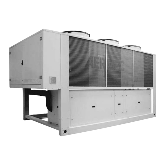
AERMEC nra 800 Installationshandbuch
Luftgekühlte luft-wasser kaltwassersätze, wärmepumpen und verflüssiger
mit scroll-verdichtern nra-serie
Inhaltsverzeichnis
Verfügbare Sprachen
Verfügbare Sprachen
INSTALLATION MANUAL
MANUEL D'INSTALLATION
INSTALLATIONSHANDBUCH
MANUAL INSTALACIÓN
Air / water chillers and heat pumps and condensing units with scroll
compressors
Centrales de production d'eau glacée et pompes à chaleur et unités de
condensation avec compresseurs scroll
Luftgekühlte Luft-Wasser Kaltwassersätze, Wärmepumpen und Verflüssiger
mit Scroll-Verdichtern
Enfriadoras y bombas de calor aire agua y motocondensadores con
compresores scroll
nra
INRAIU. 0705. 4034405_01
sostituisce il. 0607. 4034405_00
Kapitel
Inhaltsverzeichnis

Verwandte Anleitungen für AERMEC nra 800


Inhaltszusammenfassung für AERMEC nra 800
- Seite 1 INSTALLATION MANUAL MANUEL D'INSTALLATION INSTALLATIONSHANDBUCH MANUAL INSTALACIÓN Air / water chillers and heat pumps and condensing units with scroll compressors Centrales de production d'eau glacée et pompes à chaleur et unités de condensation avec compresseurs scroll Luftgekühlte Luft-Wasser Kaltwassersätze, Wärmepumpen und Verflüssiger mit Scroll-Verdichtern Enfriadoras y bombas de calor aire agua y motocondensadores con compresores scroll...
- Seite 42 Unsachgemäßer Gebrauch ....................................pag. Sehr geehrter Kunde, Wir danken Ihnen für den Vorzug für ein Produkt von AERMEC. Dieses Produkt ist das Ergebnis langjähriger Erfahrung und spezieller Entwurfstudien und wurde mit erstklassigen Materialien und fortschrittlichster Technologie gebaut. Weiters garantiert die Kennzeichnung CE, dass die Apparate den Vorraussetzungen der Europäischen Maschinenrichtlinie bezüglich Sicherheit entsprechen.
-
Seite 43: Konformitätserklärung
AERMEC S.p.A. I-37040 Bevilacqua (VR) Italia – Via Roma, 44 Tel. (+39) 0442 633111 Telefax 0442 93730 – (+39) 0442 93566 www.aermec.com - info@aermec.com NRA H MODELL: SERIEN-NR.: KONFORMITÄTSERKLÄRUNG Wir zeichnen eigenverantwortlich, dass die oben genannte Maschineneinheit, bestehend aus: Identifikation des Produkts KALTWASSERSATZ LUFT/WASSER, WÄRMEPUMPEN SERIE NRA... -
Seite 44: Umsetzung
ERHALT DES PRODUKTS 1. 1 UMSETZUNG gut befestigt sind. trieb muss die Einheit auf einer perfekt - Der Aufhängungspunkt des Heberah- waagrechten Fläche installiert werden. Vor der Montage der Einheit von den Ma- mens muss auf der Vertikalen des Prüfen Sie, ob die Stellfläche für das Ge- ßen, Gewichten, dem Schwerpunkt und Schwerpunkts liegen;... -
Seite 45: Position Der Schwingungsdämpfer
POSITION DER SCHWINGUNGSDÄMPFER NRA "0800 - 0900 - 1000" NRA "1250 - 1400 - 1500" NRA "1650 - 1800" Fig. 2... -
Seite 46: Position Der Schwingungsdämpfer Konfiguration Mit Wasser
2. 1 POSITION DER SCHWINGUNGSDÄMPFER KONFIGURATION MIT WASSER Schwerpunkt MOD. Ausf. Gewicht ° 2363 1745 • • • • ° 3237 1773 1085 • • • • ° 3300 1775 1098 • • • • ° 3266 1774 1091 • •... - Seite 47 Schwerpunkt MOD. Ausf. Gewicht 3536 1783 1075 • • • • 3505 1783 1069 • • • • 3594 1784 1086 • • • • 3549 1777 1079 • • • • 3616 1783 1064 • • • • 3549 1777 1079 •...
- Seite 48 Schwerpunkt MOD. Ausf. Gewicht 1250 4262 2094 1033 • • • • 1250 4358 2088 1049 • • • • 1250 4305 2095 1028 • • • • 1250 4375 2095 1028 • • • • 1250 4305 2095 1028 •...
- Seite 49 Schwerpunkt MOD. Ausf. Gewicht 1500 4423 2097 1047 • • • • 1500 4393 2102 1031 • • • • 1500 4463 2102 1031 • • • • 1500 4393 2102 1031 • • • • 1500 4463 2102 1031 •...
- Seite 50 Schwerpunkt MOD. Ausf. Gewicht 1800 ° 3890 2500 • • • • • • 1800 ° 4000 2529 • • • • • • 1800 ° 3920 2508 • • • • • • 1800 ° 4060 2544 • • •...
-
Seite 51: Wasserkreis
WASSERKREIS 3. 1 WASSERKREIS - Abflussventil a l l e n M o d e l l e n N R A ( m i t o d e r INNEN (Serienausstattungen) ohne Pufferspeicher) und für alle – “NRA P1/P2/P3/P4 (nur, Pumpe mit Wasserkreise, die den Kaltwassersatz Die Einheit wir d in den folgenden hoher oder niedriger Förderhöhe sowie... -
Seite 52: Nra 01/02/03/04/05/06/07 (Ausführungen Mit Hydronik-Set)
3.2.2 NRA 01/02/03/04/05/06/07 (AUSFÜHRUNGEN MIT HYDRONIK-SET) LE GEN DE 1 Pumpe/n Strömungswächter Filter montiert 4 Plattenaustauscher mit eingebautem elektrischem 5 Ausdehnungsgefäße 2 zu 25 l 700 l 6 Pufferspeicher 7 Energiegruppe 8 Belüftungsventil ANM.: Die Abbildungen sind nur indika- tiv, mit ihnen sollen die in den verschiedenen Versionen vorhan- denen Komponenten dargestellt werden. -
Seite 53: Wasserkreis Extern Empfohlen
Ausführungen ohne - Prüfen Sie vor dem Starten des Gerätes, des Verdampfers in der Dokumentation Hydronik-Set ob alle hydraulischen Anschlüsse richtig von Aermec. - Pumpe ausgeführt und die Angaben auf den - Prüfen Sie die richtige Funktionsweise des - Inertial-Pufferspeicher Schildern eingehalten wurden. -
Seite 54: Position Der Wasseranschlüsse
POSITION DER WASSERANSCHLÜSSE 4. 1 NRA 0800 - 0900 - 1000 “NRA 0800 - 0900 - 1000 00” LEGENDE 00 Standard ohne Hydronikkit “NRA 0800 - 0900 - 1000 01 - 03 - 05 - 07” LEGENDE 01 Pufferspeicher mit Pumpe mit niedriger Förderhöhe 03 Puf ferspeicher mit Pumpe mit hoher Förderhöhe... - Seite 55 NRA 1250 - 1400 - 1500 “NRA 1250 - 1400 - 1500 00” LEGENDE 00 Standard ohne Hydronikkit “NRA 1250 - 1400 - 1500 01 - 03 - 05 - 07” LEGENDE 01 Puf f er speicher mit Pumpe mit niedriger Förderhöhe 03 Pufferspeicher mit Pumpe mit hoher Förderhöhe...
- Seite 56 NRA 1650 / 1800 “NRA 1650 / 1800 02 - 04 - 06 - 08” LEGENDE 02 Pufferspeicher mit Pumpe mit niedriger Förderhöhe und Reservepumpe 04 Pufferspeicher mit Pumpe mit hoher Förderhöhe und Reservepumpe Pufferspeicher mit Bohrungen für integrierte Heizwiderstände, Pumpe m i t n i e d r i g e r F ö...
- Seite 57 NRA da 0800 al 1500 WASSERANSCHLÜSSE MIT VOLLSTÄNDIGER RÜCKGEWINNUNG “NRA 800 - 900 - 1000 - 1250 - 1400 - 1500 mit GESAMT-RÜCKGEWINNUNG” WASSERANSCHLÜSSE MIT VOLLSTÄNDIGER RÜCKGEWINNUNG A mm B mm C mm D mm IN - OUT 0800 1260 Victaulic 3”...
-
Seite 58: Elektrische Daten
ELEKTRISCHE ANSCHLÜSSE Die Einheit wird im Werk steckerfertig des effektiven Standorts zu dimensionie- Das Anziehen von allen Klemmen des vorbereitet und benötigt für die Inbetrieb- ren. Alle Stromanschlüsse müssen ge- Leistungsleiters bei der ersten Inbetrieb- nahme die Stromversorgung laut den mäß... -
Seite 59: Füllen Entleeren Der Anlage
den Phasen RST 400V ±10% beträgt. Nach der genauen Durchführung aller 6.2.3 Unterkühlung Prüfen Sie außerdem, dass die Un- oben beschriebenen Kontrollen ist es symmetrie zwischen den Phasen nicht möglich, das Gerät durch Betätigen der Prüfen Sie die Unterkühlung prüfen und über 3% liegt. -
Seite 60: Unsachgemäßer Gebrauch
UNSACHGEMÄSSER GEBRAUCH Die Konstruktion und der Bau des Gerätes 7. 1 WICHTIGE Achtung gewährleisten höchste Sicherheit in un- SICHERHEITSHINWEISE In Folge von außergewöhnlichen Wartungs- mittelbarer Geräteumgebung (IP24) sowie arbeiten eine hohe Witterungsbeständigkeit. Die Maschine darf die der Tabelle im Ab- am Kühlkreis, bei denen auch ein Austausch Die oberen Ventilatoren sind vor versehent- schnitt "Funktionsgrenzen"... - Seite 80 Les données techniques reportées dans la documentation suivante n'engagent en aucune manière Aermec. Aermec se réserve la faculté le droit d'effectuer à tout moment les modifications qu'elle jugera nécessaires à l'amélioration du produit Die technischen Daten in der vorliegenden Dokumentation sind unverbindlich.