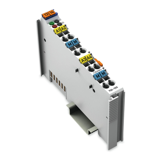
WAGO 750-555 Handbuch
Inhaltsverzeichnis
Quicklinks
Pos: 2 /Dokumentation allgemein/Einband/Einband Handbuch - Frontseite 2015 - mit DocVariablen (Standard) @ 9\mod_1285229289866_0.docx @ 64941 @ @ 1
WAGO-I/O-SYSTEM 750
Manual
750-555
4AO 0-20mA
4-Channel Analog Output Module 0-20 mA
Version 1.2.0
Pos: 3 /Alle Serien (Allgemeine Module)/Hinweise zur Dokumentation/Impressum für Standardhandbücher - allg. Angaben, Anschriften, Telefonnummern und E-Mail-Adressen @ 3\mod_1219151118203_21.docx @ 21060 @ @ 1
Kapitel
Inhaltsverzeichnis

Verwandte Anleitungen für WAGO 750-555


Inhaltszusammenfassung für WAGO 750-555
- Seite 1 Pos: 2 /Dokumentation allgemein/Einband/Einband Handbuch - Frontseite 2015 - mit DocVariablen (Standard) @ 9\mod_1285229289866_0.docx @ 64941 @ @ 1 WAGO-I/O-SYSTEM 750 Manual 750-555 4AO 0-20mA 4-Channel Analog Output Module 0-20 mA Version 1.2.0 Pos: 3 /Alle Serien (Allgemeine Module)/Hinweise zur Dokumentation/Impressum für Standardhandbücher - allg. Angaben, Anschriften, Telefonnummern und E-Mail-Adressen @ 3\mod_1219151118203_21.docx @ 21060 @ @ 1...
- Seite 2 WAGO-I/O-SYSTEM 750 750-555 4AO 0-20mA © 2015 by WAGO Kontakttechnik GmbH & Co. KG All rights reserved. WAGO Kontakttechnik GmbH & Co. KG Hansastraße 27 D-32423 Minden Phone: +49 (0) 571/8 87 – 0 Fax: +49 (0) 571/8 87 – 1 69 E-Mail: info@wago.com...
-
Seite 3: Inhaltsverzeichnis
2.1.1 Subject to Changes ................9 2.1.2 Personnel Qualifications ............... 9 2.1.3 Use of the WAGO-I/O-SYSTEM 750 in Compliance with Underlying Provisions ................9 2.1.4 Technical Condition of Specified Devices ......... 10 Safety Advice (Precautions) ..............11 Device Description ..................13 View ...................... - Seite 4 Table of Contents WAGO-I/O-SYSTEM 750 750-555 4AO 0-20mA 7.1.2 Marking for America According to NEC 500 ........40 Installation Regulations ................41 7.2.1 Special Conditions for Safe Use (ATEX Certificate TÜV 07 ATEX 554086 X) ..............42 7.2.2 Special Conditions for Safe Use (ATEX Certificate TÜV 12 ATEX 106032 X) ..............
-
Seite 5: Notes About This Documentation
Pos: 9 /Alle Serien (Allgemeine Module)/Überschriften für alle Serien/Hinweise zur Dokumentation/Gültigkeitsbereich - Überschrift 2 @ 12\mod_1338912448776_21.docx @ 96469 @ 2 @ 1 Validity of this Documentation Pos: 10 /Serie 750 (WAGO-I/O-SYSTEM)/Hinweise zur Dokumentation/Gültigkeitsbereich/Gültigkeitsbereich Dokumentation Busklemme 750-xxxx, ohne Variantenangabe @ 14\mod_1358944037947_21.docx @ 109346 @ @ 1 This documentation is only applicable to the I/O module 750-555 (4AO 0-20mA). -
Seite 6: Symbols
Notes about this Documentation WAGO-I/O-SYSTEM 750 750-555 4AO 0-20mA Pos: 12.3 /Alle Serien (Allgemeine Module)/Überschriften für alle Serien/Hinweise zur Dokumentation/Symbole - Überschrift 2 @ 13\mod_1351068042408_21.docx @ 105270 @ 2 @ 1 Symbols Pos: 12.4.1 /Alle Serien (Allgemeine Module)/Wichtige Erläuterungen/Sicherheits- und sonstige Hinweise/Gefahr/Gefahr: _Warnung vor Personenschäden allgemein_ - Erläuterung @ 13\mod_1343309450020_21.docx @ 101029 @ @ 1... - Seite 7 WAGO-I/O-SYSTEM 750 Notes about this Documentation 750-555 4AO 0-20mA Additional Information: Refers to additional information which is not an integral part of this documentation (e.g., the Internet). Pos: 12.5 /Dokumentation allgemein/Gliederungselemente/---Seitenwechsel--- @ 3\mod_1221108045078_0.docx @ 21810 @ @ 1 Manual Version 1.2.0...
-
Seite 8: Number Notation
Notes about this Documentation WAGO-I/O-SYSTEM 750 750-555 4AO 0-20mA Pos: 12.6 /Alle Serien (Allgemeine Module)/Hinweise zur Dokumentation/Darstellung der Zahlensysteme - Überschrift 2 und Inhalt @ 3\mod_1221059454015_21.docx @ 21711 @ 2 @ 1 Number Notation Table 1: Number Notation Number Code... -
Seite 9: Important Notes
All changes to the coupler or controller should always be carried out by qualified personnel with sufficient skills in PLC programming. Pos: 15.5 /Serie 750 (WAGO-I/O-SYSTEM)/Wichtige Erläuterungen/Bestimmungsgemäße VerwendungBestimmungsgemäße Verwendung 750-xxxx - Überschrift 3 und Inhalt @ 3\mod_1224064151234_21.docx @ 24070 @ 3 @ 1 2.1.3... -
Seite 10: Technical Condition Of Specified Devices
Important Notes WAGO-I/O-SYSTEM 750 750-555 4AO 0-20mA Appropriate housing (per 94/9/EG) is required when operating the WAGO-I/O- SYSTEM 750 in hazardous environments. Please note that a prototype test certificate must be obtained that confirms the correct installation of the system in a housing or switch cabinet. -
Seite 11: Safety Advice (Precautions)
Pos: 15.10.2 /Serie 750 (WAGO-I/O-SYSTEM)/Wichtige Erläuterungen/Sicherheits- und sonstige Hinweise/Gefahr/Gefahr: Einbau 0750-xxxx nur in Gehäusen, Schränken oder elektrischen Betriebsräumen! @ 6\mod_1260180556692_21.docx @ 46731 @ @ 1 Install the device only in appropriate housings, cabinets or in electrical operation rooms! The WAGO-I/O-SYSTEM 750 and its components are an open system. - Seite 12 Important Notes WAGO-I/O-SYSTEM 750 750-555 4AO 0-20mA Do not use any contact spray! Do not use any contact spray. The spray may impair contact area functionality in connection with contamination. Pos: 15.11.5 /Alle Serien (Allgemeine Dokumente) (Allgemeine Module)/Wichtige Erläuterungen/Sicherheitshinweise/Achtung/Achtung: Verpolung vermeiden! @ 6\mod_1260184045744_21.docx @ 46767 @ @ 1...
-
Seite 13: Device Description
Connection examples are shown in section “Connecting Devices” > … > “Connection Example(s)”. Pos: 18.1.6 /Serie 750 (WAGO-I/O-SYSTEM)/Wichtige Erläuterungen/Sicherheits- und sonstige Hinweise/Hinweis/Hinweis: AI Unzulässige Kombination der Bürdenwerte @ 5\mod_1247123924611_21.docx @ 36962 @ @ 1 ΩΩ Avoid any unacceptable combination of load impedance values! The output load impedance values for an I/O module must always be situated within a range of 0 ... - Seite 14 Pos: 18.1.15 /Serie 750 (WAGO-I/O-SYSTEM)/Gerätebeschreibung/Einleitung/Einsatzbereich/Einsatzbereich 750-xxxx alle Koppler/Controller ohne Economy-Koppler @ 3\mod_1232541867468_21.docx @ 26525 @ @ 1 The I/O module 750-555 can be used with all fieldbus couplers/controllers of the WAGO-I/O-SYSTEM 750 (except for the economy types 750-320, -323, -324 and -327).
-
Seite 15: View
Pos: 18.4 /Serie 750 (WAGO-I/O-SYSTEM)/Gerätebeschreibung/Ansicht/Analogausgangsklemmen/Ansicht 750-0555 @ 20\mod_1406288820623_21.docx @ 160281 @ @ 1 Figure 1: View Pos: 18.5 /Serie 750 (WAGO-I/O-SYSTEM)/Gerätebeschreibung/Ansicht/Ansicht CageClamp®_Legende mit LEDs, mit 1 Entriegelungslasche @ 15\mod_1370867188922_21.docx @ 122225 @ @ 1 Table 3: Legend for Figure “View”... -
Seite 16: Connectors
Do not place the I/O modules on the gold spring contacts in order to avoid soiling or scratching! Pos: 18.9.3 /Serie 750 (WAGO-I/O-SYSTEM)/Wichtige Erläuterungen/Sicherheits- und sonstige Hinweise/Achtung/Achtung: ESD - Auf gute Erdung der Umgebung achten! @ 7\mod_1266318538667_21.docx @ 50708 @ @ 1 Ensure that the environment is well grounded! The devices are equipped with electronic components that may be destroyed by electrostatic discharge. -
Seite 17: Power Jumper Contacts/Field Supply
Pos: 18.12.3 /Serie 750 (WAGO-I/O-SYSTEM)/Gerätebeschreibung/Anschlüsse/Leistungskontakte 2 LK (Messer/Leistungskontakte 2 LK (Messer/Feder) - Abbildung, einfache Breite - Standard @ 15\mod_1367500700037_21.docx @ 118396 @ @ 1 Figure 3: Power Jumper Contacts Pos: 18.12.4 /Serie 750 (WAGO-I/O-SYSTEM)/Gerätebeschreibung/Anschlüsse/Leistungskontakte 2 LK (Messer/Leistungskontakte 2 LK (Messer/Feder) - Legende @ 15\mod_1371721352500_21.docx @ 123710 @ @ 1... - Seite 18 Device Description WAGO-I/O-SYSTEM 750 750-555 4AO 0-20mA Use supply modules for ground (earth)! The I/O module has no power jumper contacts for receiving and transmitting the earth potential. Use a supply module when an earth potential is needed for the subsequent I/O modules.
-
Seite 19: Cage Clamp ® Connectors
WAGO-I/O-SYSTEM 750 Device Description 750-555 4AO 0-20mA Pos: 18.14 /Serie 750 (WAGO-I/O-SYSTEM)/Gerätebeschreibung/Anschlüsse/CAGE CLAMP-Anschlüsse - Überschrift 3 @ 6\mod_1256296337770_21.docx @ 43674 @ 3 @ 1 ® 3.2.3 CAGE CLAMP Connectors Pos: 18.15 /Serie 750 (WAGO-I/O-SYSTEM)/Gerätebeschreibung/Anschlüsse/Analogausgangsklemmen/Anschlüsse 750-055x 4 AO 2-Leiter @ 20\mod_1406282476661_21.docx @ 160093 @ @ 1 ®... -
Seite 20: Display Elements
Pos: 18.17 /Alle Serien (Allgemeine Module)/Überschriften für alle Serien/Gerätebeschreibung/Anzeigeelemente - Überschrift 2 @ 4\mod_1240984390875_21.docx @ 31964 @ 2 @ 1 Display Elements Pos: 18.18 /Serie 750 (WAGO-I/O-SYSTEM)/Gerätebeschreibung/Anzeigeelemente/Analogausgangsklemmen/Anzeigeelemente 750-0555 4AO (Agn, Brt) @ 20\mod_1406807365639_21.docx @ 160777 @ @ 1 Figure 5: Display Elements Table 6: Legend for Figure “Display Elements”... -
Seite 21: Schematic Diagram
Pos: 18.22 /Alle Serien (Allgemeine Module)/Überschriften für alle Serien/Gerätebeschreibung/Schematisches Schaltbild - Überschrift 2 @ 4\mod_1240984441312_21.docx @ 31967 @ 2 @ 1 Schematic Diagram Pos: 18.23 /Serie 750 (WAGO-I/O-SYSTEM)/Gerätebeschreibung/Schematische Schaltbilder/Analogausgangsklemmen/Schematisches Schaltbild 750-0555 @ 20\mod_1406289693384_21.docx @ 160285 @ @ 1 Figure 6: Schematic Diagram Pos: 18.24 /Dokumentation allgemein/Gliederungselemente/---Seitenwechsel--- @ 3\mod_1221108045078_0.docx @ 21810 @ @ 1... -
Seite 22: Technical Data
Pos: 18.25 /Alle Serien (Allgemeine Module)/Überschriften für alle Serien/Gerätebeschreibung/Technische Daten - Überschrift 2 @ 3\mod_1232967587687_21.docx @ 26924 @ 2 @ 1 Technical Data Pos: 18.26 /Serie 750 (WAGO-I/O-SYSTEM)/Gerätebeschreibung/Technische Daten/Analogausgangsklemmen/Technische Daten 75x-0555 @ 20\mod_1406645074175_21.docx @ 160541 @ 3333 @ 1 3.6.1 Device Data Table 7: Technical Data –... -
Seite 23: Connection Type
Data contacts Slide contact, hard gold plated, self- cleaning Pos: 18.29 /Serie 750 (WAGO-I/O-SYSTEM)/Gerätebeschreibung/Technische Daten/Klimatische Umgebungsbedingungen/Technische Daten Klimat. Umgebungsbed. ohne erw. Temp. 0...55°C/-25...+85°C @ 5\mod_1247657968368_21.docx @ 37603 @ 3 @ 1 3.6.6 Climatic Environmental Conditions Table 14: Technical Data – Climatic Environmental Conditions Operating temperature range 0 °C …... -
Seite 24: Approvals
> WAGO-I/O-SYSTEM 750 > System Description. Pos: 18.33 /Serie 750 (WAGO-I/O-SYSTEM)/Gerätebeschreibung/Zulassungen/Allgemein/Zulassungen Busklemme 750-xxxx Allgemein, ohne Variantenangabe - Einleitung @ 4\mod_1237460656921_21.docx @ 28643 @ @ 1 The following approvals have been granted to 750-555 I/O modules: Pos: 18.34.1 /Alle Serien (Allgemeine Dokumente) (Allgemeine Module)/Zulassungen/Standardzulassungen/CE (Konformitätskennzeichnung) @ 3\mod_1224494777421_21.docx @ 24276 @ @ 1... - Seite 25 Device Description 750-555 4AO 0-20mA Pos: 18.40 /Serie 750 (WAGO-I/O-SYSTEM)/Gerätebeschreibung/Zulassungen/Schiff/Zulassungen Busklemme 750-xxxx Schiff, ohne Variantenangabe - Einleitung @ 4\mod_1237190918453_21.docx @ 28420 @ @ 1 The following ship approvals have been granted to 750-555 I/O modules: Pos: 18.41.1 /Alle Serien (Allgemeine Dokumente) (Allgemeine Module)/Zulassungen/Schiffszulassungen/ABS (American Bureau of Shipping) @ 3\mod_1224055151062_0.docx @ 24023 @ @ 1 ABS (American Bureau of Shipping) Pos: 18.41.2 /Alle Serien (Allgemeine Dokumente) (Allgemeine Module)/Zulassungen/Schiffszulassungen/BSH (Bundesamt für Seeschifffahrt und Hydrographie) @ 5\mod_1246341825156_21.docx @ 36334 @ @ 1...
-
Seite 26: Standards And Guidelines
Pos: 18.43 /Alle Serien (Allgemeine Module)/Überschriften für alle Serien/Gerätebeschreibung/Normen und Richtlinien - Überschrift 2 @ 4\mod_1242804031875_21.docx @ 33646 @ 2 @ 1 Standards and Guidelines Pos: 18.44 /Serie 750 (WAGO-I/O-SYSTEM)/Gerätebeschreibung/Normen und Richtlinien/EMV-Normen Busklemme 750-xxxx, ohne Variantenangabe - Einleitung @ 4\mod_1242803944015_21.docx @ 33642 @ @ 1 750-555 I/O modules meet the following requirements on emission and immunity of interference: Pos: 18.45 /Alle Serien (Allgemeine Module)/Normen und Richtlinien/EMV-Normen - Standard/EMV CE-Störaussendung EN 61000-6-4 @ 4\mod_1242798273984_21.docx @ 33602 @ @ 1... -
Seite 27: Process Image
Pos: 19 /Alle Serien (Allgemeine Module)/Überschriften für alle Serien/__ noch nicht einsortierte Überschriften müssen noch einsortiert werden __/Prozessabbild - Überschrift 1 @ 4\mod_1240983067828_21.docx @ 31942 @ 1 @ 1 Process Image Pos: 20 /Serie 750 (WAGO-I/O-SYSTEM)/Prozessabbild Klemmenbus/Hinweis: Prozessabbildmapping abhängig von FBK/PFC, ohne Status-/Controlbyte @ 6\mod_1256126797251_21.docx @ 43340 @ @ 1 Mapping of process data in the process image of fieldbus systems The representation of the process data of some I/O modules or their variants in the process image depends on the fieldbus coupler/controller used. -
Seite 28: Mounting
The blade contacts are sharp-edged. Handle the I/O module carefully to prevent injury. Pos: 24.3 /Serie 750 (WAGO-I/O-SYSTEM)/Wichtige Erläuterungen/Sicherheits- und sonstige Hinweise/Achtung/Achtung: Busklemmen nur in vorgesehener Reihenfolge stecken! @ 6\mod_1256194177073_21.docx @ 43429 @ @ 1 Insert I/O modules only from the proper direction! All I/O modules feature grooves for power jumper contacts on the right side. -
Seite 29: Inserting And Removing Devices
Mounting 750-555 4AO 0-20mA Pos: 24.6 /Serie 750 (WAGO-I/O-SYSTEM)/Montieren/Demontieren/Geräte einfügen und entfernen - Überschrift 2 @ 3\mod_1231768483250_21.docx @ 25950 @ 2 @ 1 Inserting and Removing Devices Pos: 24.7 /Alle Serien (Allgemeine Module)/Wichtige Erläuterungen/Sicherheits- und sonstige Hinweise/Achtung/Achtung: Arbeiten an Geräten nur spannungsfrei durchführen! @ 6\mod_1256193963573_21.docx @ 43426 @ @ 1 Perform work on devices only if they are de-energized! Working on energized devices can damage them. -
Seite 30: Removing The I/O Module
Mounting WAGO-I/O-SYSTEM 750 750-555 4AO 0-20mA Pos: 24.10 /Serie 750 (WAGO-I/O-SYSTEM)/Montieren/Demontieren/Busklemme entfernen @ 4\mod_1239169375203_21.docx @ 30334 @ 3 @ 1 5.2.2 Removing the I/O Module Remove the I/O module from the assembly by pulling the release tab. Figure 9: Removing the I/O Module (Example) Electrical connections for data or power jumper contacts are disconnected when removing the I/O module. -
Seite 31: Connect Devices
Failure to observe these measures can damage the product! Pos: 28 /Serie 750 (WAGO-I/O-SYSTEM)/Anschließen/Leiter an CAGE CLAMP anschließen (allgemein) - Überschrift 2 und Text @ 3\mod_1225448660171_21.docx @ 24928 @ 2 @ 1 ® Connecting a Conductor to the CAGE CLAMP ®... - Seite 32 Connect Devices WAGO-I/O-SYSTEM 750 750-555 4AO 0-20mA ® For opening the CAGE CLAMP insert the actuating tool into the opening above the connection. Insert the conductor into the corresponding connection opening. ® For closing the CAGE CLAMP simply remove the tool. The conductor is now clamped firmly in place.
-
Seite 33: Connection Example
Pos: 30 /Alle Serien (Allgemeine Module)/Überschriften für alle Serien/Anschließen/Anschlussbeispiel - Überschrift 2 @ 4\mod_1242621672468_21.docx @ 33293 @ 2 @ 1 Connection Example Pos: 31 /Serie 750 (WAGO-I/O-SYSTEM)/Anschließen/Anschlussbeispiele/Analogausgangsklemmen/Anschlussbeispiele 750-055x @ 20\mod_1406711317754_21.docx @ 160608 @ @ 1 Figure 11: Connecting Diagram Pos: 32 /Dokumentation allgemein/Gliederungselemente/---Seitenwechsel--- @ 3\mod_1221108045078_0.docx @ 21810 @ @ 1 Manual Version 1.2.0... -
Seite 34: Use In Hazardous Environments
Pos: 33.1 /Alle Serien (Allgemeine Module)/Einsatz in Ex-Bereichen/Einsatz in explosionsgefährdeten Bereichen - Überschrift 1 @ 3\mod_1224075191281_21.docx @ 24084 @ 1 @ 1 Use in Hazardous Environments Pos: 33.2 /Serie 750 (WAGO-I/O-SYSTEM)/Einsatz in Ex-Bereichen/Einsatzbereich Serie 750 @ 3\mod_1234272230203_21.docx @ 27500 @ @ 1 The WAGO-I/O-SYSTEM 750 (electrical equipment) is designed for use in Zone 2 hazardous areas. -
Seite 35: Marking Configuration Examples
Pos: 33.4 /Serie 750 (WAGO-I/O-SYSTEM)/Einsatz in Ex-Bereichen/Beispielhafter Aufbau der Kennzeichnung - Überschrift 2 @ 3\mod_1224157499140_21.docx @ 24182 @ 2 @ 1 Marking Configuration Examples Pos: 33.5 /Serie 750 (WAGO-I/O-SYSTEM)/Einsatz in Ex-Bereichen/Kennzeichnung für Europa gemäß ATEX und IEC-EX - Überschrift 3 @ 3\mod_1224157620203_21.docx @ 24185 @ 3 @ 1 7.1.1 Marking for Europe According to ATEX and IEC-Ex Pos: 33.6 /Serie 750 (WAGO-I/O-SYSTEM)/Einsatz in Ex-Bereichen/Beispielbedruckung der ATEX- und IEC-Ex-zugelassenen Busklemmen gemäß... -
Seite 36: Table 16: Description Of Marking Example For Approved
Use in Hazardous Environments WAGO-I/O-SYSTEM 750 750-555 4AO 0-20mA Table 16: Description of Marking Example for Approved I/O Modules According to ATEX and IECEx Printing on Text Description TÜV 07 ATEX 554086 X Approving authority and certificate numbers IECEx TUN 09.0001 X... - Seite 37 750-555 4AO 0-20mA Pos: 33.8 /Serie 750 (WAGO-I/O-SYSTEM)/Einsatz in Ex-Bereichen/Beispielbedruckung der Ex-i- und IEC-Ex-i-zugelassenen Busklemmen gemäß CENELEC und IEC_2013 @ 14\mod_1360569320118_21.docx @ 111298 @ @ 1 Figure 14: Side Marking Example for Approved Ex i I/O Modules According to ATEX and IECEx.
-
Seite 38: Table 17: Description Of Marking Example For Approved Ex I I/O Modules According To Atex And Iecex
Use in Hazardous Environments WAGO-I/O-SYSTEM 750 750-555 4AO 0-20mA Table 17: Description of Marking Example for Approved Ex i I/O Modules According to ATEX and IECEx Inscription Text Description TÜV 07 ATEX 554086 X Approving authority and certificate numbers IECEx TUN 09.0001X TÜV 12 ATEX 106032 X... - Seite 39 WAGO-I/O-SYSTEM 750 Use in Hazardous Environments 750-555 4AO 0-20mA Table 17: Description of Marking Example for Approved Ex i I/O Modules According to ATEX and IECEx Gases Equipment group: All except mining 3(1)G Category 3 (Zone 2) equipment containing a safety...
-
Seite 40: Marking For America According To Nec 500
Use in Hazardous Environments WAGO-I/O-SYSTEM 750 750-555 4AO 0-20mA Pos: 33.10 /Serie 750 (WAGO-I/O-SYSTEM)/Einsatz in Ex-Bereichen/Kennzeichnung für Amerika gemäß NEC 500 - Überschrift 3 @ 3\mod_1224158423187_21.docx @ 24188 @ 3 @ 1 7.1.2 Marking for America According to NEC 500 Pos: 33.11 /Serie 750 (WAGO-I/O-SYSTEM)/Einsatz in Ex-Bereichen/Beispielbedruckung gemäß... -
Seite 41: Installation Regulations
WAGO-I/O-SYSTEM 750 Use in Hazardous Environments 750-555 4AO 0-20mA Pos: 33.13 /Alle Serien (Allgemeine Module)/Einsatz in Ex-Bereichen/Errichtungsbestimmungen - Überschrift 2 @ 3\mod_1232453624234_21.docx @ 26370 @ 2 @ 1 Installation Regulations Pos: 33.14 /Alle Serien (Allgemeine Module)/Einsatz in Ex-Bereichen/Errichtungsbestimmungen Einleitung_2013 @ 14\mod_1360582328318_21.docx @ 111371 @ @ 1... -
Seite 42: Special Conditions For Safe Use (Atex Certificate Tüv 07 Atex 554086 X)
WAGO-I/O-SYSTEM 750 750-555 4AO 0-20mA Pos: 33.16 /Serie 750 (WAGO-I/O-SYSTEM)/Einsatz in Ex-Bereichen/Besondere Bedingungen für den sicheren Ex-Betrieb gem. ATEX-Zertifikat TÜV 07 ATEX 554086_X_2013_2 @ 15\mod_1368620071975_21.docx @ 119778 @ 3 @ 1 7.2.1 Special Conditions for Safe Use (ATEX Certificate TÜV 07... -
Seite 43: Special Conditions For Safe Use (Atex Certificate Tüv 12 Atex 106032 X)
Use in Hazardous Environments 750-555 4AO 0-20mA Pos: 33.18 /Serie 750 (WAGO-I/O-SYSTEM)/Einsatz in Ex-Bereichen/Besondere Bedingungen für den sicheren Ex-Betrieb gem. ATEX-Zertifikat TÜV 12 ATEX 106032x_2013_2 @ 15\mod_1368620479454_21.docx @ 119782 @ 3 @ 1 7.2.2 Special Conditions for Safe Use (ATEX Certificate TÜV 12... -
Seite 44: Special Conditions For Safe Use (Iec-Ex Certificate Tun 09.0001 X)
Use in Hazardous Environments WAGO-I/O-SYSTEM 750 750-555 4AO 0-20mA Pos: 33.20 /Serie 750 (WAGO-I/O-SYSTEM)/Einsatz in Ex-Bereichen/Besondere Bedingungen für den sicheren Ex-Betrieb gem. IEC-Ex-Zertifikat TUN 09.0001 X_2013_2 @ 15\mod_1368620660911_21.docx @ 119786 @ 3 @ 1 7.2.3 Special Conditions for Safe Use (IEC-Ex Certificate TUN 09.0001 X) -
Seite 45: Special Conditions For Safe Use (Iec-Ex Certificate Iecex Tun 12.0039 X)
Use in Hazardous Environments 750-555 4AO 0-20mA Pos: 33.22 /Serie 750 (WAGO-I/O-SYSTEM)/Einsatz in Ex-Bereichen/Besondere Bedingungen für den sicheren Ex-Betrieb gem. IEC-Ex-Zertifikat TUN 12.0039 X_2013_2 @ 15\mod_1368620821493_21.docx @ 119790 @ 3 @ 1 7.2.4 Special Conditions for Safe Use (IEC-Ex Certificate IECEx TUN 12.0039 X) -
Seite 46: Special Conditions For Safe Use According To Ansi/Isa 12.12.01
Use in Hazardous Environments WAGO-I/O-SYSTEM 750 750-555 4AO 0-20mA Pos: 33.24 /Serie 750 (WAGO-I/O-SYSTEM)/Einsatz in Ex-Bereichen/Errichtungsbestimmungen ANSI ISA 12.12.01_2013_2 @ 15\mod_1368620942842_21.docx @ 119794 @ 3 @ 1 7.2.5 Special Conditions for Safe Use According to ANSI/ISA 12.12.01 “This equipment is suitable for use in Class I, Division 2, Groups A, B, C, D or non-hazardous locations only.”... -
Seite 47: List Of Figures
WAGO-I/O-SYSTEM 750 List of Figures 750-555 4AO 0-20mA Pos: 35 /Dokumentation allgemein/Verzeichnisse/Abbildungsverzeichnis - Überschrift oG und Verzeichnis @ 3\mod_1219222916765_21.docx @ 21080 @ @ 1 List of Figures Figure 1: View ....................... 15 Figure 2: Data Contacts ..................16 Figure 3: Power Jumper Contacts ................. 17 ®... -
Seite 48: List Of Tables
List of Tables WAGO-I/O-SYSTEM 750 750-555 4AO 0-20mA Pos: 37 /Dokumentation allgemein/Verzeichnisse/Tabellenverzeichnis - Überschrift oG und Verzeichnis @ 3\mod_1219222958703_21.docx @ 21084 @ @ 1 List of Tables Table 1: Number Notation ..................8 Table 2: Font Conventions ..................8 Table 3: Legend for Figure “View” ..............15 Table 4: Legend for Figure “Power Jumper Contacts”... - Seite 49 WAGO-I/O-SYSTEM 750 750-555 4AO 0-20mA Pos: 39 /Dokumentation allgemein/Einband/Einband Handbuch - Leerseite für durch 2 teilbare Seitenzahl (Standarddruck) @ 3\mod_1219230851078_0.docx @ 21123 @ @ 1 Manual Version 1.2.0...
- Seite 50 Pos: 40 /Dokumentation allgemein/Einband/Einband Handbuch - Rückseite 2015 @ 9\mod_1285229376516_21.docx @ 64944 @ @ 1 WAGO Kontakttechnik GmbH & Co. KG Postfach 2880 • D-32385 Minden Hansastraße 27 • D-32423 Minden Phone: 05 71/8 87 – 0 Fax: 05 71/8 87 – 1 69 E-Mail: info@wago.com...