
Verwandte Anleitungen für Ceag ZB 96


Inhaltszusammenfassung für Ceag ZB 96
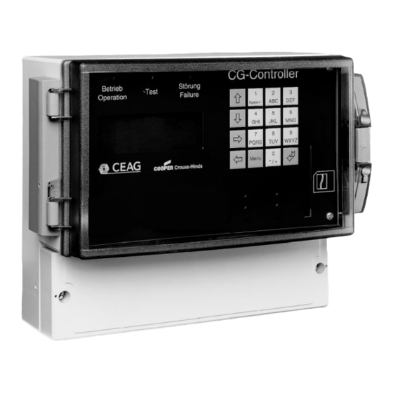
- Seite 1 Betriebsanleitung CG-Controller ZB 96 Zielgruppe: Elektrofachkräfte Operating instructions CG-Controller ZB 96 Target group: Qualified electrical personnel 300 80 001 362 (A)
-
Seite 2: Inhaltsverzeichnis
1. Inhalt 1. Content Sicherheitshinweise ..3 Safety notes ....13 Normenkonformität ..3 Conformity with Technische Daten ..3 standards ....13 4.2 Kurzbeschreibung/ Technical data ..... 13 Verwendungsbereich ..3 4.2 Brief description/Field of Installation ..... 4 application ....13 5.1 Montage ...... -
Seite 3: Sicherheitshinweise
96 entsprechend den im Ab- Anzeigenfeld schnitt Installation der Beleuchtetes Display, Bertriebsanleitung ZB 96 alphanummerisch 4 x 20 Zeichen (CEAG Nr. 400 71 346 035 genannten Anweisungen ge- Mechanische Daten prüft werden! Schutzklasse: II Schutzart nach Beachten Sie bei allen... -
Seite 4: Installation
Steckplatz 1 Steckplatz 2 Busleitungen Die Busleitung (EGA) von den angeschlossenen CEAG ZB 96- Anlagen ist an den Klemmen E - G - A (Bild 3) anzuschließen. Sollte eine LON Schnittstellen- karte auf dem 2. Steckplatz in- stalliert sein, so ist gemäß Bild... -
Seite 5: Programmierung
6. Programmierung Beachten Sie die für die Notbeleuchtung gültigen Errichtungs- bestimmungen! Eine unsachge- mäße Programmierung kann die Wirksamkeit der Notbeleuch- Alphanumerische Tastatur LEDs für tung außer Kraft setzen! Betrieb Test Störung 6.1 Programmierung ohne Speicherkarte Grundmenü: M e n u Info Geräte <... -
Seite 6: Prüfbuch
Nächster Funk.-test 18:00 14.09.99 - - - - - - - - - - - - - - - - - - V V Die angeschlossenen ZB 96 Abstand in Tagen: 03 Geräte müssen am Controller angemeldet werden. Programmierung: M e n u Info Geräte... - Seite 7 6.1.1 Erstinbetriebnahme wählt Anzahl der Lade Grundeinstellungen booster in der Anlage < < < < < Gerätesetup Strang Update ZB/US Strang zurück beendet die Programmierung: ZB96/US96 01↑↓ Nicht installiert↓ Pfeil oben/ unten wählt die Nr. der ange- schlossenen ZB96/US96 Anla ge aus.
-
Seite 8: Geräteinformationen
6.1.2 Geräteinformationen 6.1.3 Manuelle Testabläufe M e n u M e n u Info Geräte < Info Geräte Manueller Test Manueller Test < Blockieren/Quittier. Blockieren/Quittier. Controllereinstell. Controllereinstell. Prüfbuch Prüfbuch Ende Wählt den Testmodus Wählt den Infomodus F-Test starten < ZB/US96 01↑↓ ↵... - Seite 9 6.1.4 Blockieren/Quittieren 6.1.5 Prüfbuch Das Prüfbuch ist in dieser Ver- M e n u sion nicht verfügbar (nur mit se- paraten Speicherkarte und Le- Info Geräte segerät) Manueller Test Blockieren/Quittier< Controllereinstell. Prüfbuch Wählt den Blockier/ Quittiermodus Alle ZB/US blockier< Alle ZB/US freigeben Tiefentl.
-
Seite 10: Programmierung Mit Speicherkarte
6.2 Programmierung mit ZB96/US96 01↑↓ Speicherkarte Installiert↑ Alle Grundfunktionen unter 6.1 Geräte Setup ↵ werden unterstützt. SKU Setup ↵ Zusätzliche Funktionen: Leuchtenbeschreibungstext für ca. 1000 Leuchten Pfeil 3 x rechts, Enter öffnet alphanummerisch mit max. SKU-Setup 20 Zeichen/Leuchte ZB/US96 01,SKU1/1→←↵ SKU-Programmierung BGT1:_ _ _ _ _ _ _ _ Stromkreis- oder... -
Seite 11: Betrieb
6.2.1 Leuchtenbeschreibungs- Einzelüberwachung Einzelüberwachung ↑ ↑ texte - - - - - - - - - - - - - - - - - - - - - - - - - - - - - - - ..5 ..10..15..20 . -
Seite 12: Speicherkarte Am Pc Bearbeiten
6.3 Speicherkarte am PC bearbeiten Diese Option benötigt eine be- sondere Software und ist auf Anfrage zu beziehen. 6.4 LON Schnittstelle Die LON Schnittstelle dient zum Anschluß an externe Über- wachunssysteme z.B. Gebäudeleittechnik. Das Daten- protokoll wird gesondert zur Verfügung gestellt. 7. - Seite 24 CEAG Notlichtsysteme GmbH Senator-Schwartz-Ring 26 D-59494 Soest / Germany Telefon + 49 29 21/69-870 Telefax + 49 29 21/69-617 Internet http://www.ceag.de E-Mail Info-n@ceag.de...