
Verwandte Anleitungen für Ceag TLS-BUS-Modul


Inhaltszusammenfassung für Ceag TLS-BUS-Modul
- Seite 1 Montage- und Betriebsanleitung Mounting and Operating Instructions TLS-BUS-Modul / TLS-BUS-Module Zielgruppe: Elektrofachkraft Target group: Skilled electricians...
-
Seite 2: Normenkonformität
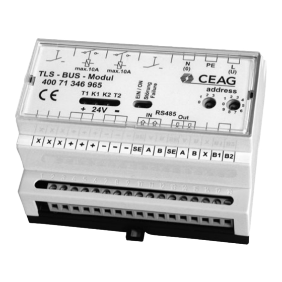
Sicherheits- und (zur Erzeugung der Glimm- Unfallverhütungsvorschrif- Das elektronische Schaltgerät lampenspannung) mit der CEAG ten und die nachfolgenden dient in Verbindung mit CEAG Notlichtanlage verbunden. Sicherheitshinweise in der Sicherheitsbeleuchtungs- Die Tastfunktion wird an die Betriebsanleitung, die mit anlagen Typ ZB-S und CEAG Notlichtanlage über den... - Seite 3 Netzspannung muss über eine separate Stromkreisumschaltung = 3PH (SKU) von der Notlichtanlage er- address folgen (gesichertes Netz). Adressierung Vor Betrieb an einer CEAG- Sicherheitsbeleuchtungsanlage 3 PH muss die Moduladressierung vorgenommen werden. Hierzu ist mit einem geeigneten Schrauben- dreher die gewünschte Adresse (1...
- Seite 4 Empfolene Leitung: JY(ST)Y 4 x 2 x 0,8 mm, Twisted Pair (verdrillte Zweidraht-Leitung), geschirmt Keine Stichleitungen zulässig! * Im TLS-Bus-Modul ist der 120 Ohm-Abschlußwiderstand integriert und kann durch eine Brücke an den Klemmen B1/B2 aktiviert werden. Bitte lesen Sie dazu auch Seite 3.
-
Seite 5: Safety Instructions
2.5 mm² rigid The switches are supplied from Observe the national safety and flexible a CEAG emergency lighting sys- rules and regulations for tem with a protected supply. The prevention of accidents as Description/Scope of module has 2 switch phases each... - Seite 6 (protected 3 PH mains). S485 Addressing Prior to operation in a CEAG safety lighting system, the module address must be set. B1 B2 For this purpose the required address (1 - 25) is to be set on the code switches on the mod- fig.
- Seite 7 recommend cable: JY(ST)Y 4 x 2 x 0.8 mm, twisted pair, shielded No dead-end lines allowed. * In TLS-Bus-modul the 120 ohms terminating resistor is integrated and can be activate through a wire fitted to terminals B1/B2. Please read back page 6.
- Seite 8 CEAG Notlichtsysteme GmbH Cooper Safety Senator-Schwartz-Ring 26 Jephson Court 59494 Soest Tancred Close Germany Royal Leamington Spa Warwickshire CV31 3RZ Tel: +49 (0) 2921/69-870 United Kingdom Fax: +49 (0) 2921/69-617 Web: www.ceag.de Tel: +44 (0) 1926 439200 Email: info-n@ceag.de Fax:...