
Verwandte Anleitungen für Ceag DLS/3PH-BUS-Modul


Inhaltszusammenfassung für Ceag DLS/3PH-BUS-Modul
- Seite 1 Montage- und Betriebsanleitung Mounting and Operating Instructions DLS/3PH-BUS-Modul / DLS/3PH-BUS-Module Zielgruppe: Elektrofachkraft Target group: Skilled electricians...
-
Seite 2: Sicherheitshinweise
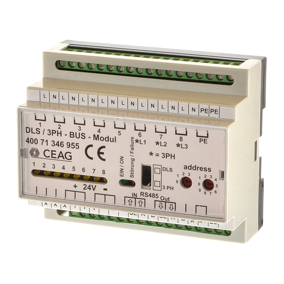
Die RS 485 Schnittstelle so- beiten am Gerät ist sicher- und flexibel wie die Spannungsversorgung zustellen, dass das Gerät 24 V DC wird von der CEAG- span nungs frei geschaltet Beschreibung/ Sicherheitsbeleuch tungs anlage ist! Beachten Sie dabei versorgt. Der 230 V-Schaltbe-... - Seite 3 Montage und Betriebsanleitung DLS/3PH-BUS-Modul Adressierung Vor Betrieb an einer CEAG- Sicherheitsbeleuchtungsanlage muss die Moduladressierung DLS / 3PH - BUS - Modul vorgenommen werden. Hier- 400 71 346 955 = 3PH zu ist mit einem geeigneten address Schraubendreher die ge- wünschte Adresse (1 - 25) an...
- Seite 4 Bei Unterbrechung oder Kurzschluss der Busleitung wird die programmierte Sicherheitsbeleuchtung auf Dauerlicht geschaltet. * Im DLS/3Ph-Bus-Modul ist der 120 Ohm-Abschlusswiderstand integriert und kann durch eine Brücke an den Klemmen B1/B2 aktiviert werden. Bitte lesen Sie dazu auch Seite 2.
- Seite 5 1-8 is forwarded prevention of accidents as for the safety lighting can be to the CEAG emergency light- well as the safety instruc- switched together during mains ing system over the BUS. The tions included in these operation.
- Seite 6 Mounting and Operating Instructions DLS/3PH-BUS-Module Addressing Prior to operation in a CEAG DLS / 3PH - BUS - Modul safety lighting system, the 400 71 346 955 = 3PH module address must be set. address For this purpose the required...
- Seite 7 Mounting and Operating Instructions DLS/3PH-BUS-Module General lighting Safety lighting next Module fig. 3: Wiring of the DLS/3PH BUS-Module RS485-BUS ZB-S *Terminating Terminating resistor resistor 120 Ω 120 Ω max. 1200 m with J-Y(ST)Y 4 x 2 x 0.8 mm fig.4 Bus-structure RS485-BUS ...
- Seite 8 CEAG Notlichtsysteme GmbH Cooper Safety Senator-Schwartz-Ring 26 Jephson Court 59494 Soest Tancred Close Germany Royal Leamington Spa Warwickshire CV31 3RZ Tel: +49 (0) 2921/69-870 United Kingdom Fax: +49 (0) 2921/69-617 Web: www.ceag.de Tel: +44 (0) 1926 439200 Email: info-n@ceag.de Fax:...