BRAWA E75 Betriebs-/Wartungsanleitung
Quicklinks
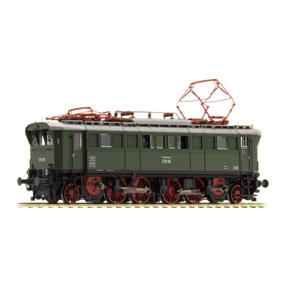
Betriebs-/Wartungsanleitung Ellok E75
Operating/Maintenance Instructions Electric Locomotive E75
Verwendete Symbole/Used Symbols
NEM Schacht demontieren
Dismantling the NEM shaft
Bitte beachten Sie die in dieser Bedienungsanleitung verwendeten Sym-
bole:
Please refer to the symbols used in this operating instructions:
2
.
Arbeitsschritt Demontage/Work step dismantling
29
Positionsnummer Ersatzteil (Pos.)
Position no. of spare part (Pos.)
Ölen/Lubricating
Arbeiten vor der Inbetriebnahme
Work to be performed before starting up
Allgemeine Montage und Sicherheitshinweise
• Diese Bedienungsanleitung beschreibt sämtliche Arbeitsvorgänge die zur
Wartung und Instandhaltung notwendig sind.
Bitte lesen Sie diese Bedienungsanleitung bevor Sie mit den Arbeiten
beginnen.
• Bei unsachgemäßem Umgang mit elektrischen Bauteilen können diese
zerstört werden. Für entsprechende Arbeiten (z.B. Platinenwechsel)
1. Zusatzbauteile montieren
1. Fitting additional parts
können Sie sich an Ihren Fachhändler oder den Hersteller wenden.
Dem Modell liegt ein Zurüstbeutel bei, von dem eventuell nicht alle Teile benötigt
There is an accessory bag added to the model but may be not all parts will be
werden. Die Zurüstteile sind für Vitrinenmodelle gedacht, da es nach dem Mon-
needed. The additional parts are intended for showcase. After mounting the
• Bei den folgenden Wartungsarbeiten ist die jeweilige Demontage beschrie-
tieren der Zurüstteile zu Einschränkungen im Fahrbetrieb kommen kann.
additional parts, there can be limitations in driving mode.
ben, der Zusammenbau ist in umgekehrter Reihenfolge auszuführen.
• 1 = 4x Bremsschlauch rechts
• 1 = 4x Brake hose right
• 2 = 2x Kupplungsimitation
• 2 = 2x Heating pipe
• Die folgenden Wartungsarbeiten sind bei Gleich und
• 3 = 4x Bremsschlauch links
• 3 = 4x Brake hose left
WechselstromAusführungen fast identisch. Im Ausnahmefall wird im
entsprechenden Abschnitt Bezug genommen.
Vorne/Front
• Jegliche Kabel oder Verbindungsdrähte die in diesem Produkt verbaut sind
dürfen nicht in eine Netzsteckdose eingeführt werden. Lebensgefahr!
General assembly and safety information
• These operating instructions describe all work steps necessary for
maintenance and repair. Please read these operating instructions carefully
before you start with your work.
• In the case of incorrect handling of electrical components, they may be
destroyed. Please ask your specialist dealer to help with the necessary
work (e.g. changing circuit boards).
1
• In the case of maintenance work, the disassembly is described below, to
2
reassemble the tractor reverse the work steps.
3
• The maintenance work described below is virtually identical for direct
current and alternating current models. If there are any differences these
2. Umrüsten auf Digitalbetrieb
2. Converting to digital operation
will be pointed out specifically.
Gleichstrom Ausführung
DC version
• All cables and connection wires installed in this product may not be
Siehe Punkt 4.
See item 4.
inserted in a mains socket. Danger!
Den richtigen Einbau des Digitaldecoders und dessen Einsteckrichtung
Please consult the installation instructions issued by the decoder manufac-
entnehmen Sie der Einbauvorschrift des Decoderherstellers.
turer for correct installation of the digital decoder and its insert direction.
WechselstromAusführung
AC version
The digital decoder (01) is standard for the alternating current (AC) locomotives
L
okomotiven in WechselstromAusführung AC werden serienmäßig mit Digital-
models. The decoder independently identifies the operation type (analog/digital).
decoder (01) ausge l iefert. Der Decoder erkennt die Betriebsart (analog/digital)
selbstständig. Soll der Decoder umprogramiert werden, liegt die Einbau und
Please refer to the enclosed installation and operation instructions "Digital Decoder"
Betriebsanleitung Digitaldecoder bei.
in the event that the decoder needs to be reprogrammed.
Der Decoder ist Werkseitig auf Adresse 03 eingestellt.
The decoder is set to address 03 in the factory.
3. Gehäuse/Pantograf/Lautsprecher demontieren
2
.
Arbeitsschritt Demontage/Work step dismantling
Dismantling pantograph/speaker
Positionsnummer Ersatzteil (Pos.)
29
Position no. of spare part (Pos.)
Hinten/Back
4. Digitaldecoder/Sounddecoder/Analogstecker tauschen
Exchanging the digital decoder/sound decoder/blind plug
5. Platine demontieren,
Dismantling the PCB
4
S3:
Abschalten Licht Führerstand vorne,
bei Digitalbetrieb = AUX3 /
Turn off light Driver's cabin front,
at digital mode = AUX3
S4:
Abschalten Licht Führerstand hinten,
bei Digitalbetrieb = AUX4 /
Turn off light Driver's cabin back,
at digital mode = AUX4
S5:
Abschalten Licht weiss, vorne oben /
Turn off light white, front at the top
S6:
Abschalten Licht weiss, hinten oben /
Turn off light white, back at the top
6. Kardan/Schnecke tauschen
2
.
Arbeitsschritt Demontage/Work step dismantling
Exchanging the cardan/worm gear
Positionsnummer Ersatzteil (Pos.)
29
Position no. of spare part (Pos.)
S1:
Abschalten Licht vorne, rot /
Turn off light front, red
S2:
Abschalten Licht hinten, rot /
Turn off light back, red
7. Bügelkupplung/NEM Schacht demontieren
2
.
Arbeitsschritt Demontage/Work step dismantling
Dismantling the standard coupler/NEM shaft
Positionsnummer Ersatzteil (Pos.)
29
Position no. of spare part (Pos.)
8. Kuppelstangen demontieren
Dismantling the coupling rod
Fortsetzung auf der Rückseite!
Continuation on the reverse side!

Verwandte Anleitungen für BRAWA E75


Inhaltszusammenfassung für BRAWA E75
- Seite 1 Betriebs-/Wartungsanleitung Ellok E75 Operating/Maintenance Instructions Electric Locomotive E75 Verwendete Symbole/Used Symbols NEM Schacht demontieren 3. Gehäuse/Pantograf/Lautsprecher demontieren Arbeitsschritt Demontage/Work step dismantling 6. Kardan/Schnecke tauschen Arbeitsschritt Demontage/Work step dismantling 7. Bügelkupplung/NEM Schacht demontieren Arbeitsschritt Demontage/Work step dismantling Dismantling the NEM shaft...
- Seite 2 Bolt, short 0002390.00 • • • • • • • • • • • • licht nicht richtungsabhängig sondern muß über 2 Funktionstasten Coupling sound+Air Coupling sound+Air Decoder DH22-4 (E75) Decoder DH22-4 (E75) 0014764.04 – – • – – – • – – – • – F5+F6 Lok abgestellt (2x rot je Seite )/ Loco parked (2x red/Side) ein- bzw. ausgeschaltet werden (siehe Funktionstastenbelegung).