Inhaltsverzeichnis
Werbung
Verfügbare Sprachen
Verfügbare Sprachen
Werbung
Kapitel
Inhaltsverzeichnis

Verwandte Anleitungen für Telecom Behnke 21-2906A-IP


Inhaltszusammenfassung für Telecom Behnke 21-2906A-IP
- Seite 1 Version 3.2 IP-Kamera, 20-2906A-IP/21-2906A-IP, 20-2913A-IP/21-2913A-IP, 43-9582-IP Seite ..3 IP camera, Page ..17 20-2906A-IP/21-2906A-IP, 20-2913A-IP/21-2913A-IP, 43-9582-IP Caméra IP, 20-2906A-IP/21-2906A-IP, 20-2913A-IP/21-2913A-IP, 43-9582-IP Page ..31...
-
Seite 2: Service-Hotline
Bei Netzwerkgeräten sind die einschlägigen Seite 14. Normen und Regeln der Netzwerktechnik zu beachten. KontaKt Info-Hotline Telecom Behnke GmbH Ausführliche Informationen zu Produkten, Gewerbepark „An der Autobahn“ Projekten und unseren Dienstleistungen: Robert-Jungk-Straße 3 +49 (0) 68 41 / 81 77-700... -
Seite 3: Inhaltsverzeichnis
Anleitung IP-Kamera Inhalt inhalt 1. Einleitung 1.1. Lieferumfang ........................4 1.2. Allgemeines ........................4 ▸ Leistungsmerkmale ......................4 ▸ Kameraposition bestimmen ....................4 ▸ Videostream abrufen ......................4 1.3. IP-Kameramodul ......................6 1.4. IP-Hinterbaukamera ......................6 1.5. Anschluss IP-Kamera ......................7 ▸ LAN-Anschluss........................7 ▸ Stromversorgung ......................7 2. -
Seite 4: Einleitung
Das Behnke Kameramodul integriert eine Kamera Objekt oder eine Person zu richten. Beleuchtung, vom Typ Axis M3045 hinter einer Blende des Kameraöffnungswinkel (horizontal / vertikal), Telecom Behnke Modulsystems der Serien 20 Reflektionen durch Fremdlicht und Sonnenein- oder 30. strahlung, Gegenlicht und Totzone sind Faktoren, die die Bildqualität später im Betrieb maßgeblich... - Seite 5 Anleitung IP-Kamera Einleitung „http://<Benutzer>:<Passwort>@<ip-addr>/ betreiben. axis-cgi/mjpg/video.cgi?resolution=1920x1080“ Es sind alle gängigen Regeln der Netzwerk- technik zu beachten Weitere Möglickeiten können Sie der AXIS-Doku- Reinigung und Pflege mentation zur VAPIX-Schnittstelle entnehmen. Systemvoraussetzungen Sie haben hochwertige Behnke Produkte mit Frontblenden aus verschiedenen Materialien Zur Installation der Behnke IP-Kamera sind fol- verbaut.
-
Seite 6: Ip-Kameramodul
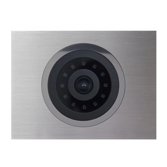
Anleitung IP-Kamera Einleitung 1.3. IP-Kameramodul 1.4. IP-Hinterbaukamera 20-2913A-IP 21-2913A-IP 43-9582 Kameralinse Dome Beleuchtungsring mit weißen LEDs (LEDs dauer an im Auslieferungszustand) 20-2906A-IP 21-2906A-IP www.behnke-online.de... -
Seite 7: Anschluss Ip-Kamera
Strom- versorgung der Kamera mittels PoE über die IP-Basiselektronik. Beleuchtungsring Kameras mit Beleuchtungsring (20-2906A-IP und 21-2906A-IP) verfügen über ein zusätzliches Anschlusskabel ( Seite 8 + 9) zur Stromversorgung des Beleuchtungsrings. Dieser kann ständig mit Strom versorgt werden. Alter- nativ ist eine Schaltung über Relais 2 der SIP-... - Seite 8 Anleitung IP-Kamera Einleitung LED-Beleuchtungsring der Kamera dauerhaft eingeschaltet Basiselektronik IP Input Output Kameramodul Rückseite LAN-Kabel (inkl. PoE zur Kamera) Anschlusskabel zur Stromversorgung des Beleuchtungsrings www.behnke-online.de...
- Seite 9 Anleitung IP-Kamera Einleitung LED-Beleuchtungsring der Kamera im Aus- lieferungszustand nur während des Gesprächs eingeschaltet. Basiselektronik IP Input Output Kameramodul Rückseite LAN-Kabel (inkl. PoE zur Kamera) Anschlusskabel zur Stromversorgung des Beleuchtungsrings Die Aktivierung des Beleuchtungsrings ist von der Konfiguration der Betriebsart für Relais 2 in der SIP-Sprechstelle abhängig.
-
Seite 10: Konfiguration Und Inbetriebnahme
Anleitung IP-Kamera Konfiguration und Inbetriebnahme Konfiguration und inbetriebnahme 2.1. Vorbereitung 2.3. Benutzername und Passwort ▸ Verbindung der IP-Videokamera mit einem Benutzername: root 100 Mbit Ethernet LAN Passwort: Admin ▸ Stromversorgung via Power over Ethernet (PoE) oder passendem Netzteil 2.4. Videostream per Browser abrufen Verbindung über Ethernet Videostream abrufen: Die IP Kamera ist im Standard als DHCP-Client... -
Seite 11: Reset Auf Werkseinstellungen
Anleitung IP-Kamera Konfiguration und Inbetriebnahme 2.5. Reset auf Werkseinstellungen Folgende Einstellungen sind nach dem Reset unbedingt wieder durchzuführen: ▸ ▸ Kamera stromlos machen 1. Kamera Passwort vergeben ▸ ▸ Reset-Taster drücken und gedrückt halten 2. Capture Mode: 1080P(1920x1080) ▸ ▸ Kamera mit Strom versorgen, dabei Taste 3. -
Seite 12: Technische Daten
Anleitung IP-Kamera Technische Daten technische daten 20-2906A-IP/21-2906A-IP, 20-2913A-IP/ 43-9582 21-2913A-IP Ausstattung ▸ Ausstattung Stromversorgung via PoE ▸ Stromversorgung via PoE (siehe „Stromversor- ▸ Digitaler PTZ gung“ auf Seite 7) ▸ ONVIF Kompatibel zum Einsatz mit Video- ▸ LED Beleuchtungsring überwachungssystemen unterschiedlicher ▸... -
Seite 13: Bemaßung
Anleitung IP-Kamera Bemaßung bemassung Hinterbau Frontalansicht Seitenansicht Ø 65 Wir empfehlen einen Hohlraumauschnitt von 120 x 120 x 40 mm (H x B x T) Elektromagnetische Verträglichkeit Niederspannungsrichtlinie Unsere Produkte sind selbstverständlich nach den CE-Richtlinien zertifiziert, die EU-weit gültig sind: EMV nach 2004/108/EG sowie Nieder- spannungsrichtlinie nach 73/23/EWG geändert durch die Richtlinie 93/68/EWG. -
Seite 14: Rechtliche Hinweise
Anleitung IP-Kamera Rechtliche Hinweise rechtliche hinweise Infos zum Produkthaftungsgesetz: 1. Änderungen an unseren Produkten, die dem technischen Fortschritt dienen, behalten wir uns vor. Die abgebildeten Produkte können im 1. Alle Produkte aus dieser Anleitung dürfen nur Zuge der ständigen Weiterentwicklung auch für den angegebenen Zweck verwendet werden. - Seite 15 IP camera Instructions instructions Version 3.0 IP-Kamera, 20-2906A-IP/21-2906A-IP, 20-2913A-IP/21-2913A-IP, 43-9582-IP Seite ..3 IP camera, 20-2906A-IP/21-2906A-IP, 20-2913A-IP/21-2913A-IP, 43-9582-IP Page ..17 Caméra IP, 20-2906A-IP/21-2906A-IP, 20-2913A-IP/21-2913A-IP, 43-9582-IP Page ..31 www.behnke-online.com...
- Seite 16 For further legal information, please see network devices. page 28. contact Information Telecom Behnke GmbH For detailed information on our product, Gewerbepark “An der Autobahn” projects and services: Robert-Jungk-Straße 3 +49 (0) 68 41/81 77-700...
- Seite 17 IP camera Instructions Contents contents 1. Introduction 1.1. What’s in the box ......................18 1.2. General Information ......................18 ▸ Features ......................... 18 ▸ Determining the camera position ..................18 ▸ Accessing the video feed ....................18 1.3. IP camera module ......................20 1.4.
-
Seite 18: Introduction
The camera is also equipped with an or people, you should consider changing the sur- LED illumination (20-2906A-IP/21-2906A-IP) for rounding area by changing the camera position. use in poorly lit areas. Where it proves to be impossible to change the... - Seite 19 IP camera Instructions Introduction Additional options can be found within the Maintenance and Care documentation on the VAPIX interface provided by AXIS. You have chosen high-quality Behnke products with front panels made from various materials. System requirements Regardless of the material, all front panels require regular cleaning in sufficiently short Minimum requirements to install Behnke IP intervals using a cleansing agent appropriate...
-
Seite 20: Ip Camera Module
IP camera Instructions Introduction 1.3. IP camera module 1.4. IP reverse side camera 20-2913A-IP 21-2913A-IP 43-9582 Camera lens Dome Illumination with white LEDs (LEDs permanently turned on in default settings) 20-2906A-IP 21-2906A-IP www.behnke-online.com... -
Seite 21: Connecting The Ip Camera
PoE from the IP basic electronics. Illumination Cameras featuring illumination (20-2906A-IP and 21-2906A-IP) are equipped with an addi- tional cable ( page 22 + 23) to supply power for the illumination unit. Continuous power supply is possible. Alternatively, you may use your SIP door intercom’s relay 2 to supply... - Seite 22 IP camera Instructions Introduction Camera LED illumination permanently turned on IP basic electronics Input Output Camera module, rear view Network cable (including PoE to camera) LED illumination power supply cable www.behnke-online.com...
- Seite 23 IP camera Instructions Introduction Camera LED illumination default setting: only turned on during a call. IP basic electronics Input Output Camera module, rear view Network cable (including PoE to camera) LED illumination power supply cable Turning on the LED illumination depends on the operations mode set for relay 2 of your SIP door intercom.
-
Seite 24: Configuration And Set-Up
IP camera Instructions Configuration and set-up configuration and set-up 2.1. Preparation 2.3. User name and password ▸ Connect the IP camera to a 100 Mbit User name: root Ethernet LAN Password: Admin ▸ Power supply via Power over Ethernet (PoE) or suitable power supply unit 2.4. -
Seite 25: Reset To Default Settings
IP camera Instructions Configuration and set-up 2.5. Reset to default settings The following settings must be performed again after the reset: ▸ ▸ Disable the camera’s power supply 1. Assign camera password ▸ ▸ Press and hold the reset key 2. -
Seite 26: Technical Specifications
IP camera Instructions Technical Specifications technical specifications 20-2906A-IP/21-2906A-IP, 20-2913A-IP/ 43-9582 21-2913A-IP Features ▸ Features Power supply via PoE ▸ Power supply via PoE (please cf. “Power ▸ Digital PTZ supply” on page 21) ▸ ONVIF compatibility to use with video surveil- ▸... -
Seite 27: Dimensions
IP camera Instructions Dimensions dimensions Reverse side mounting Front view Side view Ø 65 We suggest a cavity size of 120 x 120 x 40 mm (HxWxD) Electromagnetic Compatibility Low Voltage Directive All our products meet the standards for CE certification valid in the entire EU: Electro- magnetic Compatibility according to directive 2004/108/EC and Low Voltage Directive 73/23/EEC modified by 93/68/EEC. -
Seite 28: Legal Information
IP camera Instructions Legal Information legal information Information with regard to product liability: 1. We reserve the right to change our products, without notice, for technical progress. As a result of continuous development, the products 1. All products mentioned in these instructions illustrated may look different from the products may only be used for the purpose intended. - Seite 29 Version 3.0 IP-Kamera, 20-2906A-IP/21-2906A-IP, 20-2913A-IP/21-2913A-IP, 43-9582-IP Seite ..3 IP camera, 20-2906A-IP/21-2906A-IP, 20-2913A-IP/21-2913A-IP, 43-9582-IP Page ..17 Caméra IP, 20-2906A-IP/21-2906A-IP, 20-2913A-IP/21-2913A-IP, 43-9582-IP Page ..31...
- Seite 30 Les normes et règles applicables relatives aux Vous trouverez des informations légales périphériques réseau doivent être respectées. complémentaires sur la page 42. contact Infoligne Telecom Behnke S.à r.l. Pour des informations détaillées 1, Avenue Saint Rémy concernant nos produits, projets et nos F-57600 Forbach services : France Tél. : +33 (0)3 87 84 99 50...
- Seite 31 Notice caméra IP Sommaire sommaire 1. Introduction 1.1. Étendue de la livraison ......................32 1.2. Généralités ........................32 ▸ Caractéristiques de fonctionnement ................32 ▸ Ajuster la position de la caméra ..................32 ▸ Récupérer le flux vidéo ....................32 1.3. Module caméra IP ......................34 1.4.
-
Seite 32: Introduction
Notice caméra IP Introduction introduction La documentation correspondante est consultable sur le site internet de la société AXIS Communica- 1.1. Étendue de la livraison tions. Les méthodes de compression Motion-JPEG et H.264 sont disponibles. ▸ Module caméra IP ▸ Câble patch relié directement à la caméra La caméra prend en charge la version du firmware ▸... - Seite 33 Notice caméra IP Introduction « http://<Utilisateur>:<Mot de passe>@<ip-addr>/ Toutes les règles applicables relatives aux péri- axis-cgi/mjpg/video.cgi?resolution=1920x1080 » phériques réseau doivent être respectées. Nettoyage et entretien Vous trouverez d’autres possibilités en consultant la documentation AXIS relative à l’interface VAPIX. Vous avez installé des produits Behnke de Configuration système requise haute qualité...
-
Seite 34: Module Caméra Ip
Notice caméra IP Introduction 1.3. Module caméra IP 1.4. Caméra IP arrière 20-2913A-IP 21-2913A-IP 43-9582 Lentille de la caméra Dôme Anneau d’éclairage avec LED blanches (les LED sont toujours allumées conformément au réglage à la livraison) 20-2906A-IP 21-2906A-IP www.behnke-online.fr... -
Seite 35: Raccordement De La Caméra Ip
, la caméra est alimentée via PoE par l’électronique de base IP. Anneau d’éclairage Les caméras avec anneau d’éclairage (20- 2906A-IP et 21-2906A-IP) disposent d’un câble de raccordement ( page 36 + 37) pour l’alimentation de l’anneau d’éclairage. Il peut être alimenté... - Seite 36 Notice caméra IP Introduction Lʼanneau dʼéclairage LED de la caméra reste toujours allumé Électronique de base IP Entrée Sortie Vue arrière du module caméra B-Smart Câble LAN (y compris PoE vers la caméra) Câble de connexion pour l’alimentation électrique de l’anneau d’éclairage www.behnke-online.fr...
- Seite 37 Notice caméra IP Introduction Par défaut lors de la livraison, lʼanneau dʼéclai- rage LED de la caméra ne sʼallume que durant une conversation téléphonique. Électronique de base IP Entrée Sortie Vue arrière du module caméra B-Smart Câble LAN (y compris PoE vers la caméra) Câble de connexion pour l’alimentation électrique de l’anneau d’éclairage L’activation de l’anneau d’éclairage dépend...
-
Seite 38: Configuration Et Mise En Service
Notice caméra IP Configuration et mise en service configuration et mise en service 2.1. Préparation 2.3. Nom d’utilisateur et mot de passe ▸ Raccordement de la caméra IP à un réseau Nom d’utilisateur : root Ethernet 100 Mbit Mot de passe : Admin ▸... -
Seite 39: Remise À Zéro De La Configuration
Notice caméra IP Configuration et mise en service 2.5. Remise à zéro de la configuration Les paramètres suivants doivent être réitérés après la réinitialisation: ▸ ▸ Débrancher la caméra 1. Attribuez un mot de passe de caméra ▸ ▸ Appuyer et maintenir enfoncée la touche 2. -
Seite 40: Caractéristiques Techniques
Notice caméra IP Caractéristiques techniques caractéristiques techniques 20-2906A-IP/21-2906A-IP, 20-2913A-IP/ 43-9582 21-2913A-IP Équipement ▸ Équipement Alimentation par PoE ▸ Alimentation par PoE (voir « Alimentation ▸ PTZ numérique (PTZ = Pan/Tilt/ Zoom = Pano- électrique » à la page 35) ramique/Inclinaison/Zoom) ▸ ▸... -
Seite 41: Cotation
Notice caméra IP Cotation cotation Montage arrière Vue avant Vue latérale Ø 65 Nous recommandons un découpage montage à cloison creuse de 120 x 120 x 40 mm (H x L x P) Compatibilité électromagnétique Directive sur la basse tension Nos produits satisfont naturellement aux directives CE en vigueur dans les pays de lʼUnion européenne telles que la directive relative à... -
Seite 42: Informations Légales
Notice caméra IP Informations légales informations légales Informations relatives à la loi sur la responsa- bilité du fait des produits: 1. Nous nous réservons le droit de modifier nos produits en vertu des progrès techniques. En 1. Tous les produits de notre gamme doivent raison de l’évolution technique, les produits être utilisés conformément à... - Seite 43 Notizen / Note www.behnke-online.fr...
- Seite 44 Version 3.2 Kirkel, Mai 2018 telecom behnKe gmbh Telecom Behnke GmbH Info-Hotline: +49 (0) 68 41 / 81 77-700 Gewerbepark „An der Autobahn“ Service-Hotline: +49 (0) 68 41 / 81 77-777 Robert-Jungk-Straße 3 Telefax: +49 (0) 68 41 / 81 77-750 66459 Kirkel info@behnke-online.de...