Herunterladen Inhalt Inhalt Diese Seite drucken
Inhaltsverzeichnis

Werbung

Verfügbare Sprachen

Verfügbare Sprachen

D
IP-Kamera,
20-2940-IP/21-2940-IP, 20-2941-IP/21-2941-IP,
43-2940, 50-2940-IP
GB IP camera,
20-2940-IP/21-2940-IP, 20-2941-IP/21-2941-IP,
43-2940, 50-2940-IP
F
Caméra IP,
20-2940-IP/21-2940-IP, 20-2941-IP/21-2941-IP,
43-2940, 50-2940-IP
anleitung
Version 1.0
Seite .... 3
Page .... 19
Page .... 35

Werbung

Inhaltsverzeichnis
loading

Inhaltszusammenfassung für Telecom Behnke 20-2940-IP

  • Seite 1 Version 1.0 IP-Kamera, 20-2940-IP/21-2940-IP, 20-2941-IP/21-2941-IP, 43-2940, 50-2940-IP Seite ..3 GB IP camera, 20-2940-IP/21-2940-IP, 20-2941-IP/21-2941-IP, Page ..19 43-2940, 50-2940-IP Caméra IP, 20-2940-IP/21-2940-IP, 20-2941-IP/21-2941-IP, 43-2940, 50-2940-IP Page ..35...
  • Seite 2: Service-Hotline

    Wartungs- oder Reparaturarbeiten vom Stromnetz (Steckernetzteil) und vom Netzwerk bzw. Telefonanschluss getrennt sind und die einschlägigen Sicherheitsregeln eingehalten werden. Weitere rechtliche Hinweise finden Sie auf Seite 15. KontaKt Info-Hotline Telecom Behnke GmbH Ausführliche Informationen zu Produkten, Gewerbepark »An der Autobahn« Projekten und unseren Dienstleistungen: Robert-Jungk-Straße 3...
  • Seite 3: Inhaltsverzeichnis

    Anleitung IP-Kamera Inhalt inhalt 1. Einleitung 1.1. Lieferumfang ........................4 1.2. Allgemeines ........................5 ▸ 1.2.1. Leistungsmerkmale ....................5 ▸ 1.2.2. Kameraposition bestimmen ..................5 ▸ 1.2.3. Videostream abrufen ....................6 ▸ 1.2.4. Systemvoraussetzungen ..................6 ▸ 1.2.5. Reinigung und Pflege ..................... 6 1.3. IP-Kameramodul .......................7 1.4.
  • Seite 4: Einleitung

    Anleitung IP-Kamera Einleitung einleitung 1.1. Lieferumfang ▸ IP Kameramodul 20-2940-IP/21-2940-IP/ 50-2940-IP nur geeignet für die Montage in senkrechten Behnke-Rahmen, kann nicht ❎ ✅ im untersten Moduleinbauplatz ( ) eines Behnke-Rahmen verbaut werden, Kamerapla- tine verhindert montage des Modulgehäuses. ✅ ▸...
  • Seite 5: Allgemeines

    Das Behnke Kameramodul integriert eine Kamera vom Typ Axis M3066-V hinter einer sehr viel mehr nötig, als lediglich die Kamera Blende des Telecom Behnke Modulsystems auf ein Objekt oder eine Person zu richten. der Serien 20, 50 oder als Hinterbaukamera Beleuchtung, Kameraöffnungswinkel (horizon-...
  • Seite 6: Videostream Abrufen

    Sie z. B. folgende URL ein: Software freigegeben). Achtung bei Firmware- »http://<Benutzer>:<Passwort>@<ip-addr>/ axis-cgi/mjpg/video.cgi?resolution=1920x1080« update oder Reset der Kamera, die Schritte aus 20-2940-IP/21-2940-IP, 20-2941-IP/21-2941-IP, Seite 12 durchführen. 43-2940, 50-2940-IP 1.2.5. Reinigung und Pflege Weitere Möglickeiten können Sie der AXIS-Doku- mentation zur VAPIX-Schnittstelle entnehmen.
  • Seite 7: Ip-Kameramodul

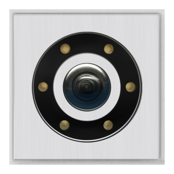
    Anleitung IP-Kamera Einleitung 1.3. IP-Kameramodul 1.4. IP-Hinterbaukamera 20-2941-IP 21-2941-IP 43-2940 20-2940-IP 21-2940-IP Kameralinse/Kameradome Beleuchtungsring mit weißen LEDs (LEDs dauer an im Auslieferungszustand) 50-2940-IP www.behnke-online.de...
  • Seite 8: Anschluss Ip-Kamera

    Anleitung IP-Kamera Einleitung 1.5. Anschluss IP-Kamera 1.5.3. Beleuchtungsring 1.5.1. LAN-Anschluss Kameras mit Beleuchtungsring verfügen über ein zusätzliches Anschlusskabel ( Der LAN-Anschluss erfolgt üblicherweise über Seite 9 + 10) zur Stromversorgung des einen RJ-45 Stecker ( Seite 9 + 10). Beleuchtungsrings. Dieser kann ständig mit Wird das Modul zusammen mit einer Basis- Strom versorgt werden.
  • Seite 9: Input Output

    Anleitung IP-Kamera Einleitung LED-Beleuchtungsring der Kamera dauerhaft eingeschaltet Basiselektronik IP Input Output Kameramodul Rückseite LAN-Kabel (inkl. PoE zur Kamera) Anschlusskabel zur Stromversorgung des Beleuchtungsrings hier direkt mit der SIP-Sprechstelle verbunden. Kann auch mit einem Beschriftungsfeld (12 V) verbunden werden. Beschriftungsfeld Anschluss siehe dazu in der Anleitung der SIP-Sprechstelle IP-Kamera darf nur mit Deckel betrieben werden.
  • Seite 10 Anleitung IP-Kamera Einleitung LED-Beleuchtungsring der Kamera im Aus- lieferungszustand nur während des Gesprächs eingeschaltet. Basiselektronik IP Input Output Kameramodul Rückseite LAN-Kabel (inkl. PoE zur Kamera) Anschlusskabel zur Stromversorgung des Beleuchtungsrings (Beleuchtung nicht bei 43-9582 / 43-9582A) Die Aktivierung des Beleuchtungsrings ist von der Konfiguration der Betriebsart für Relais 2 in der SIP-Sprechstelle abhängig.
  • Seite 11: Konfiguration Und Inbetriebnahme

    IP-Adresse also von einem z.B. »http://<Benutzer>:<Passwort>@<ip-addr>/ DHCP-Server. Mittels Axis Camera Management axis-cgi/mjpg/video.cgi?resolution=1920x1080« Software, Behnke IP-Video-Software oder im (20-2940-IP/21-2940-IP, 20-2941-IP/21-2941-IP, DHCP-Server lassen sich die vorhandenen Kame- 43-2940, 50-2940-IP) ras im Netzwerk finden. Die Rückfall IP-Adresse der Kamera lautet: Weitere Möglickeiten können Sie der AXIS-Doku-...
  • Seite 12: Reset Auf Werkseinstellungen

    ▸ Taste loslassen, wenn die LED blinkt (ca. 15 - 30 Sekunden) Folgende Einstellungen sind nach dem Reset unbedingt wieder durchzuführen: Bei 20-2940-IP/21-2940-IP, 20-2941-IP/21-2941-IP, 43-2940, 50-2940-IP: ▸ 1. Kamera Passwort vergeben ▸ 2. Capture Mode: 4MP (2304x1728) ▸...
  • Seite 13: Technische Daten

    Anleitung IP-Kamera Technische Daten technische daten 20-2940-IP/21-2940-IP, Netzwerk 20-2941-IP/21-2941-IP, 43-2940, 50-2940-IP ▸ IPv4, IPv6 USGv6, HTTP, HTTP/2, HTTPSa, SSL/ TLSa, QoS Layer 3 DiffServ, FTP, SFTP, CIFS/ Ausstattung SMB, SMTP, Bonjour, UPnP , SNMP v1/v2c/ ® ▸ Stromversorgung via PoE (siehe „1.5.2. Strom- v3 (MIB-II), DNS, DynDNS, NTP, RTSP, RTP, versorgung“...
  • Seite 14: Bemaßung

    Anleitung IP-Kamera Bemaßung bemassung Hinterbau (43-2940) Frontalansicht Seitenansicht Ø 64,8 Wir empfehlen einen Hohlraumauschnitt von 120 x 120 x 50 mm (H x B x T) Frontausschnitt Materialstärke der bauseitigen Front 2 mm Ø 65 4x Stehbolzen M3 x 10 www.behnke-online.de...
  • Seite 15: Rechtliche Hinweise

    Anleitung IP-Kamera Rechtliche Hinweise rechtliche hinweise Infos zum Produkthaftungsgesetz: 1. Änderungen an unseren Produkten, die dem technischen Fortschritt dienen, behalten wir uns vor. Die abgebildeten Produkte können im Zuge 1. Alle Produkte aus dieser Anleitung dürfen nur der ständigen Weiterentwicklung auch optisch für den angegebenen Zweck verwendet werden.
  • Seite 16 Notizen / Note www.behnke-online.de...
  • Seite 17 Version 1.0 IP-Kamera, 20-2940-IP/21-2940-IP, 20-2941-IP/21-2941-IP, 43-2940, 50-2940-IP Seite ..3 GB IP camera, 20-2940-IP/21-2940-IP, 20-2941-IP/21-2941-IP, 43-2940, 50-2940-IP Page ..19 Caméra IP, 20-2940-IP/21-2940-IP, 20-2941-IP/21-2941-IP, 43-2940, 50-2940-IP Page ..35...
  • Seite 18 For further legal information, please see page 31. contact Information: Telecom Behnke GmbH For detailed information on our product, Gewerbepark „An der Autobahn“ projects and services: Robert-Jungk-Straße 3...
  • Seite 19 IP camera Instructions Contents contents 1. Introduction 1.1. What’s in the box ......................20 1.2. General Information ......................21 ▸ 1.2.1. Features ......................... 21 ▸ 1.2.2. Determine the camera position ................21 ▸ 1.2.3. Accessing the video feed ..................22 ▸ 1.2.4. System requirements .....................22 ▸...
  • Seite 20: Introduction

    IP camera Instructions Introduction introduction 1.1. What’s in the box ▸ IP camera module 20-2940-IP/21-2940-IP/ 50-2940-IP is only suitable for mounting in vertical Behnke frames, and cannot be ❎ ✅ installed in the lowest module ( ) mount- ing position of a Behnke frame. The camera board prevents the mounting of the module ✅...
  • Seite 21: General Information

    IP camera Instructions Introduction 1.2. General Information 1.2.2. Determine the camera position 1.2.1. Features Please note the following advice on camera position when installing your Behnke door intercom system: In order to receive an image The Behnke camera module integrates an Axis M3066-V type camera behind a series 20 or feed, you need a lot more than to simply point 50 Behnke Telecom modular system or as a...
  • Seite 22: Accessing The Video Feed

    URL: (1.7 GHz) or AMD Athlon™ Processor “http://<user>:<password>@<ip-addr>/ (1.2 GHz) or better ▸ axis-cgi/mjpg/video.cgi?resolution=1920x1080“ Network interface controller, configured 20-2940-IP/21-2940-IP, 20-2941-IP/21-2941-IP, ▸ Microsoft® Windows 2000® or 43-2940, 50-2940-IP Windows XP® operating system or later ▸ 512 MB RAM or more ▸...
  • Seite 23: Ip Camera Module

    IP camera Instructions Introduction 1.3. IP camera module 1.4. IP reverse side camera 20-2941-IP 21-2941-IP 43-2940 20-2940-IP 21-2940-IP Camera lens/camera domes Illumination ring with white LEDs (LEDs permanently turned on in default settings) 50-2940-IP www.behnke-online.com...
  • Seite 24: Connecting The Ip Camera

    IP camera Instructions Introduction 1.5. Connecting the IP camera 1.5.3. LED Illumination 1.5.1. LAN connection Cameras featuring illumination are equipped with an additional cable ( page 25 + Usually, an RJ-45 connector is used to establish 26) to supply power for the illumination unit. a LAN connection ( page 25 + 26).
  • Seite 25: Input Output

    IP camera Instructions Introduction Camera LED illumination permanently turned on IP basic electronics Input Output Camera module, rear view Network cable (including PoE to camera) The illumination power supply cable is directly connected to the SIP door inter- com station here. It can also be connected to a labelling unit (12 V).
  • Seite 26 IP camera Instructions Introduction Camera LED illumination default setting: only turned on during a call. IP basic electronics Input Output Camera module, rear view Network cable (including PoE to camera) Connection cable to power the illumination ring (43-9582 / 43-9582A not illuminated) Turning on the LED illumination depends on the operations mode set for relay 2 of your...
  • Seite 27: Configuration And Set-Up

    Axis camera management software, Behnke IP e.g. „http://<Benutzer>:<Passwort>@<ip-addr>/ video software or the DHCP server, the existing axis-cgi/mjpg/video.cgi?resolution=1920x1080“ cameras can be found in the network. (20-2940-IP/21-2940-IP, 20-2941-IP/21-2941-IP, The fallback IP address of the camera is 43-2940, 50-2940-IP) 192.168.0.90 Further possibilities can be found in the AXIS documentation for the VAPIX interface.
  • Seite 28: Reset To Default Settings

    ▸ Stop pressing the key when the LED starts flashing (after approx. 15-30 seconds) The following settings must be carried out again after the reset: For 20-2940-IP/21-2940-IP, 20-2941-IP/21-2941-IP, 43-2940, 50-2940-IP: ▸ 1. Allocate camera password ▸ 2. Capture mode: 4MP (2304x1728) ▸...
  • Seite 29: Technical Specifications

    IP camera Instructions Technical Specifications technical specifications 20-2940-IP/21-2940-IP, Network 20-2941-IP/21-2941-IP, 43-2940, 50-2940-IP ▸ IPv4, IPv6 USGv6, HTTP, HTTP/2, HTTPSa, SSL/ TLSa, QoS Layer 3 DiffServ, FTP, SFTP, CIFS/ Features SMB, SMTP, Bonjour, UPnP , SNMP v1/v2c/ ® ▸ Power supply via PoE(please cf. “1.5.2. Power v3 (MIB-II), DNS, DynDNS, NTP, RTSP, RTP, supply”...
  • Seite 30: Dimensions

    IP camera Instructions Dimensions dimensions Rear end (43-2940) Front view Side view Ø 64,8 We suggest a cavity size of 120 x 120 x 50 mm (HxWxD) Front cutout Material thickness of the front on site 2 mm Ø 65 4x Stud bolt M3 x 10 www.behnke-online.com...
  • Seite 31: Legal Information

    IP camera Instructions Legal Information legal information Information with regard to product liability: 1. We reserve the right to change our products, without notice, in line with technical progress. As a result of continuous development, the 1. All products mentioned in these instructions products illustrated may look different from may only be used for the purpose intended.
  • Seite 32 GB GB Notizen / Notes www.behnke-online.com...
  • Seite 33 Version 1.0 IP-Kamera, 20-2940-IP/21-2940-IP, 20-2941-IP/21-2941-IP, 43-2940, 50-2940-IP Seite ..3 GB IP camera, 20-2940-IP/21-2940-IP, 20-2941-IP/21-2941-IP, 43-2940, 50-2940-IP Page ..19 Caméra IP, 20-2940-IP/21-2940-IP, 20-2941-IP/21-2941-IP, 43-2940, 50-2940-IP Page ..35...
  • Seite 34 électrique (bloc d’alimentation), informatique et téléphonique et respec- ter les règles de sécurité en vigueur. Vous trouverez des informations légales complémentaires sur la page 47. contact Infoligne Telecom Behnke S.à r.l. Pour des informations détaillées 1, Avenue Saint Rémy concernant nos produits, projets et nos F-57600 Forbach...
  • Seite 35 Notice caméra IP Sommaire sommaire 1. Introduction 1.1. Étendue de la livraison ......................36 1.2. Généralités ........................37 ▸ 1.2.1. Caractéristiques de fonctionnement ................37 ▸ 1.2.2. Déterminer la position de la caméra ...............37 ▸ 1.2.3. Afficher le flux vidéo ....................38 ▸ 1.2.4. Configuration système requise ................38 ▸...
  • Seite 36: Introduction

    Notice caméra IP Introduction introduction 1.1. Étendue de la livraison ▸ Le module de caméra IP 20-2940-IP/21-2940- IP/50-2940-IP convient uniquement au montage dans des cadres verticaux Behnke, et ne peut ✅ pas être installé dans la position de montage ❎...
  • Seite 37: Généralités

    Notice caméra IP Introduction 1.2. Généralités 1.2.2. Déterminer la position de la caméra 1.2.1. Caractéristiques de fonctionnement Veuillez prendre en compte les informations suivantes sur la position de la caméra lors de l’installation du portier téléphonique Le module caméra Behnke intègre une caméra de type Axis M1054 derrière un cache du sys- Behnke : afin d’obtenir une image, il ne suffit tème modulaire Behnke des séries 20, 30, 50...
  • Seite 38: Afficher Le Flux Vidéo

    (si elle est mise à disposition par Behnke en « http ://<user> :<password>@<ip-addr>/ axis-cgi/ mjpg/video.cgi ?resolution=1920x1080 » association avec le logiciel Behnke IP Video). 20-2940-IP/21-2940-IP, 20-2941-IP/21-2941-IP, Pour mettre à jour le Firmware ou réinitialiser la 43-2940, 50-2940-IP caméra, veuillez suivre les étapes indiquées à la page 44.
  • Seite 39: Module Caméra Ip

    Notice caméra IP Introduction 1.3. Module caméra IP 1.4. Caméra IP arrière 20-2941-IP 21-2941-IP 43-2940 20-2940-IP 21-2940-IP Objectifs de caméra/caméra dôme Anneau d’éclairage avec LED blanches (LED allumées en continu à l’état de livraison) 50-2940-IP www.behnke-online.fr...
  • Seite 40: Raccordement De La Caméra Ip

    Notice caméra IP Introduction 1.5. Raccordement de la caméra IP 1.5.3. Anneau d‘éclairage 1.5.1. Raccordement LAN Les caméras avec anneau d’éclairage ont un câble de connexion supplémentaire ( Page Le raccordement LAN se fait habituellement 41 42) pour alimenter l’anneau d’éclai- par une prise RJ-45 ( Seite 41 + 42).
  • Seite 41 Notice caméra IP Introduction L’anneau d’éclairage LED de la caméra est allumé en continu Électronique de base IP Entrée Sortie Vue arrière du module caméra Câble LAN (y compris PoE vers la caméra) Câble de raccordement pour l’alimentation électrique de l’anneau d’éclairage, ici direc- tement relié...
  • Seite 42 Notice caméra IP Introduction Par défaut lors de la livraison, l’anneau d’éclai- rage LED de la caméra ne s’allume que durant une conversation téléphonique. Électronique de base IP Entrée Sortie Vue arrière du module caméra Câble LAN (y compris PoE vers la caméra) Câble de connexion pour l’alimentation électrique de l’anneau d’éclairage (éclairage non compris dans 43-9582 / 43-9582A)
  • Seite 43: Configuration Et Mise En Service

    Management, le logiciel IP vidéo Behnke ou le addr>/ axis-cgi/mjpg/video.cgi ?resolu- serveur DHCP, les caméras existantes peuvent être tion=1920x1080 » retrouvées dans le réseau.* (20-2940-IP/21-2940-IP, 20-2941-IP/21-2941-IP, L’adresse IP de repli de la caméra est 192.168.0.90 43-2940, 50-2940-IP) Vous trouverez d’autres possibilités dans la 2.2. Domaines d’application documentation AXIS pour l’interface VAPIX.
  • Seite 44: Réinitialisation Aux Paramètres D'usine

    Relâcher la touche quand la LED clignote (env. 15 - 30 secondes) Les réglages suivants doivent être effectués à nouveau après la réinitialisation : Pour 20-2940-IP/21-2940-IP, 20-2941-IP/21- 2941-IP, 43-2940, 50-2940-IP : ▸ 1. Attribuer un mot de passe à la caméra ▸...
  • Seite 45: Caractéristiques Techniques

    Notice caméra IP Caractéristiques techniques caractéristiques techniques 20-2940-IP/21-2940-IP, Réseau 20-2941-IP/21-2941-IP, 43-2940, 50-2940-IP ▸ IPv4, IPv6 USGv6, HTTP, HTTP/2, HTTPSa, SSL/ TLSa, QoS Layer 3 DiffServ, FTP, SFTP, CIFS/ Équipement SMB, SMTP, Bonjour, UPnP , SNMP v1/v2c/ ® ▸ Alimentation par PoE (voir « 1.5.2. Alimenta- v3 (MIB-II), DNS, DynDNS, NTP, RTSP, RTP, tion électrique »...
  • Seite 46: Cotation

    Notice caméra IP Cotation cotation Montage arrière (43-2940) Vue avant Vue latérale Ø 64,8 Nous recommandons un découpage montage à cloison creuse de 120 x 120 x 50 mm (H x L x P) Découpe avant Épaisseur du matériau de la façade sur place 2 mm Ø...
  • Seite 47: Informations Légales

    Notice caméra IP Informations légales informations légales Informations relatives à la loi sur la responsabilité 1. Nous nous réservons le droit de modifier nos du fait des produits : produits en vertu des progrès techniques. En raison de l’évolution technique, les produits livrés peuvent avoir une apparence différente de 1.
  • Seite 48 Version 1.0 Kirkel, Dezember 2020 telecom behnKe gmbh Telecom Behnke GmbH Info-Hotline : +49 (0) 68 41 / 81 77-700 Gewerbepark « An der Autobahn » Service-Hotline : +49 (0) 68 41 / 81 77-777 Robert-Jungk-Straße 3 Telefax : +49 (0) 68 41 / 81 77-750 66459 Kirkel info@behnke-online.de...

Diese Anleitung auch für:

21-2940-ip20-2941-ip21-2941-ip50-2940-ip

Inhaltsverzeichnis