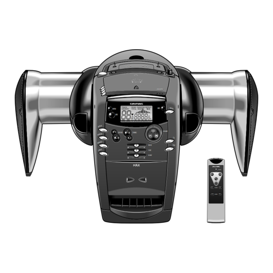
Grundig PA 1 Servicehandbuch
Inhaltsverzeichnis
Quicklinks
Service
Zusätzlich erforder-
Manual
liche Unterlagen
für den
Komplettservice:
PA 1
Additionally
required Service
Sach-Nr./Part No.
Manuals for the
72010-748.40
Complete Service:
PA 1
(9.79403-8151 / G.LF 14-51)
Remote Control
Änderungen vorbehalten
Subject to alteration
SERVICE MANUAL
Service
Manual
Sicherheit
Safety
Sach-Nr./Part No.
72010-800.00
INTRO
UBS
FM
MW
M W
R EP EA T
T
R EP EA
#
#
#
#
STATION
STATION
TUNING
TUNING
M
R AN DO M
R AN DO
$
$
$
$
M EM OR
M EM OR Y
Y
I • • • • I • • • • I • • • • I • • • • I
I • • • • I • • • • I • • • • I • • • • I
C AN CE L
C AN CE L
I • • • • I • • • • I • • • • I • • • • I
I • • • • I • • • • I • • • • I • • • • I
I • • • • I • • • • I • • • • I • • • • I
I • • • • I • • • • I • • • • I • • • • I
(75954-034.87)
Printed in Germany
VK 233 0396
I
I
PUSH OPEN
PUSH OPEN
AM /F M
AM /F M
INFO
kHz
MHz
M H z
VOLUME
VOLUME
CD
CD
100 HZ
100 HZ
TA PE
TA PE
1 KHZ
1 KHZ
10 KHZ
10 KHZ
PA 1
STBY/ON
STBY/ON
STATION
STATION
VOLUME
VOLUME
Service Manual Sach-Nr.
Service Manual Part No.
72010-748.40
Inhaltsverzeichnis

Verwandte Anleitungen für Grundig PA 1


Inhaltszusammenfassung für Grundig PA 1
- Seite 1 SERVICE MANUAL Service Service Zusätzlich erforder- Manual Manual liche Unterlagen für den Komplettservice: Sicherheit PA 1 Safety Additionally required Service Sach-Nr./Part No. Sach-Nr./Part No. Manuals for the 72010-748.40 72010-800.00 Complete Service: PA 1 PUSH OPEN PUSH OPEN AM /F M...
-
Seite 2: Inhaltsverzeichnis
Distortion Meter Testcassette 449 (Sach-Nr. 35079-019.00) Test Cassette 449 (Part No. 35079-019.00) Beachten Sie bitte das GRUNDIG Meßtechnik-Programm, das Sie Please note the Grundig Catalog “Test and Measuring Equipment” unter folgender Adresse erhalten: obtainable from: GRUNDIG electronics GmbH GRUNDIG electronics GmbH Würzburger Str. -
Seite 3: Technische Daten
PA 1 Allgemeiner Teil / General Section Technische Daten Technical Data Spannungsversorgung Power Supply Netzbetrieb ..............230V, 50/60Hz Mains operation ............230V, 50/60Hz Batteriebetrieb ........... 8 x 1,5V (R20, UM1) Battery operation ..........8 x 1.5V (R20, UM1) Ausgangsleistung DIN 45324, 10% Klirrfaktor Output power DIN 45324, 10% THD Musikleistung: ......... -
Seite 4: Ausbauhinweise
Allgemeiner Teil / General Section PA 1 Ausbauhinweise Disassembly Instructions 1. Gehäuseseitenteile 1. Cabinet Sides - Je 4 Schrauben A (Fig. 1) an den Gehäuse- - Undo 4 screws A (Fig. 1) each at the seitenteilen herausschrauben. cabinet sides. 2. Gehäuserückteil mit Lautsprechern 2. - Seite 5 PA 1 Allgemeiner Teil / General Section 6. Cassettenlaufwerk 6. Cassette Mechanism - Gehäusevorderteil abnehmen (Punkt 3). - Remove the front (para 3). - 4 Schrauben I (Fig. 8) herausschrauben. - Undo 4 screws I (Fig. 8). 7. Cassettenelektronikplatte 7. Cassette Electronic PCB - Cassettenlaufwerk ausbauen (Punkt 6).
-
Seite 6: Einleitung
Hinweis: Dieses Kapitel enthält Auszüge aus der Bedienungsanleitung. Weitergehende Informationen entnehmen Sie bitte der gerätespezifischen Bedienungsanleitung, Bedienhinweise deren Sachnummer Sie in der entsprechenden Ersatzteilliste finden. EINLEITUNG BEDIENELEMENTE POWER PACK POWER ANTENNA CD CONTROL PUSH OPEN PUSH OPEN INFO AM/ FM AM/ FM INTRO SPACE FIDELITY - DIE HAUPTVORTEILE... - Seite 7 BEDIENELEMENTE STROMVERSORGUNG ALLGEMEIN RADIO RÜCKSEITEE von MAX DISPLAY EIN- UND AUSSCHALTEN RADIO-ANTENNEN AC MAINS - Netzanschlußbuchse Das Display zeigt: • Zum Einschalten Taste POWER drücken. – Bei UKW-Empfang (FM) die Teleskopantenne herausziehen – wenn ein FM- und durch Neigen und Drehen ausrichten. Bei zu Autobatterieanschluß...
- Seite 8 CD-SPIELER CD-SPIELER UMGANG MIT CDs ÄNDERN DER DISPLAYANZEIGE WIEDERHOLTES ABSPIELEN SPEICHERN VON TITELN • Nur digitale Audio-CDs verwenden. • Drücken Sie einmal die Wenn Sie eine CD oder ein CD-Programm mehrmals hören Sie können maximal 20 Titel in jeder beliebigen Reihenfol- •...
-
Seite 9: Wartung
CASSETTENDECK WARTUNG TECHNISCHE DATEN COMPACT CASSETTEN AUFNAHME ALLGEMEIN TECHNISCHE DATEN • Verwenden Sie für die Aufnahme nur NORMAL Cas- Die Aufnahme ist nur im Rahmen der Urheberrechte oder • Der CD-Spieler und das Cassetten-Deck enthalten Spannungsversorgung setten (IEC I), bei denen die Laschen nicht anderer Rechte Dritter zulässig. -
Seite 10: Operating Hints
Note: This chapter contains excerpts from the operating instructions. For further particulars please refer to the appropriate user instructions the part number of which is indi- Operating Hints cated in the relevant spare parts list. INTRODUCTION CONTROLS POWER PACK POWER ANTENNA CD CONTROL PUSH OPEN... -
Seite 11: Power Supply
CONTROLS POWER SUPPLY GENERAL RADIO BACK SIDE of MAX DISPLAY SWITCHING ON AND OFF RADIO AERIALS AC MAINS - socket for mains lead The display shows: – For FM, pull out the telescopic aerial. To improve FM- • Press the POWER knob to switch MAX on. –... -
Seite 12: Cd-Player
CD PLAYER CD PLAYER CD HANDLING CHANGING THE DISPLAY REPEAT PLAYBACK PROGRAMMING TRACK NUMBERS • Use only Digital Audio CDs. • Press the INFO If you want to listen to a CD or a CD programme more than You may store a maximum of 20 tracks in the memory in a •... - Seite 13 CASSETTE DECK MAINTENANCE TECHNICAL DATA COMPACT CASSETTES CASSETTE RECORDING GENERAL TECHNICAL SPECIFICATIONS • For recording, use a NORMAL cassette (IEC type I) on Recording is permissible insofar as copyright or other • The mechanical parts of the CD player and the cassette Power Supply wich the tabs are not broken out.
-
Seite 14: Tuner
Abgleichvorschriften / Adjustment Procedures PA 1 Abgleichvorschriften Tuner: Meßgeräte: Wobbler, Meßsender, Stereocoder, Oszilloskop, Digitalvoltmeter, NF-Voltmeter Abgleich Vorbereitung Abgleichprozedur ± 1. MW-Oszillator Bei 603kHz mit F109 auf 1,75V 0.1V einstellen. Digitalvoltmeter an Meßpunkt A. Bei 1404kHz kontrollieren auf < 6,7V. 2. MW-ZF MW, 603kHz Mit F104 auf maximalen Pegel einstellen. -
Seite 15: Grundig Service
PA 1 Abgleichvorschriften / Adjustment Procedures Ferrit-Antenne Ferrite Antenna Rahmenantenne Frame Arial Fig. 1 Fig. 2 Abgleichlageplan Tuner Alignment Layout Tuner CN102 CN104 J128 F105 F104 F109 CT103 F103 L101 L102 L103 CN103 IC102 CT201 F108 QZ201 FC101 R124 GRUNDIG Service... -
Seite 16: Adjustment Procedures
Abgleichvorschriften / Adjustment Procedures PA 1 Adjustment Procedures Tuner: Test Equipment: Sweep generator, Test generator, Stereo coder, Oscilloscope, Digital voltmeter, AF Voltmeter Adjustment Preparation Adjustment Procedure ± 1. AM Oscillator At 603kHz adjust F109 to 1.75V 0.1V. Digital voltmeter to testpoint A. -
Seite 17: Circuit Diagrams And Layout Of Pcbs
PA 1 Schaltpläne und Druckplattenabbildungen / Circuit Diagrams and Layout of PCBs PA 1 Schaltpläne und Druckplattenabbildungen / Circuit Diagrams and Layout of PCBs Schaltpläne und Druckplattenabbildungen / Circuit Diagrams and Layout of PCBs Verdrahtungsplan / Wiring Diagram INTRO CN707... -
Seite 18: Circuit Diagrams Tuner
Schaltpläne und Druckplattenabbildungen / Circuit Diagrams and Layout of PCBs PA 1 Schaltpläne und Druckplattenabbildungen / Circuit Diagrams and Layout of PCBs PA 1 Schaltplan Tuner Circuit Diagram Tuner R137 +3.6V GAIN REDUCTION SWITCH 1/4W R241 F108 STRQ T106 441.0174.00... -
Seite 19: Layout Of Pcbs Tuner
PA 1 Schaltpläne und Druckplattenabbildungen / Circuit Diagrams and Layout of PCBs PA 1 Schaltpläne und Druckplattenabbildungen / Circuit Diagrams and Layout of PCBs Druckplattenabbildungen Tuner Layout of PCBs Tuner CN102 L206 CN105 T201 390P C204 c1923 R202 R203 120K... -
Seite 20: Control Board
Schaltpläne und Druckplattenabbildungen / Circuit Diagrams and Layout of PCBs PA 1 Schaltpläne und Druckplattenabbildungen / Circuit Diagrams and Layout of PCBs PA 1 Schaltplan Bedienteil Circuit Diagram Control Board CONTROL BOARD Seite/Page 3 - 17 TO P.AMP BD CN707... - Seite 21 PA 1 Schaltpläne und Druckplattenabbildungen / Circuit Diagrams and Layout of PCBs Druckplattenabbildungen Bedienteil Layout of PCBs Control Board Bedienplatte / Control PCB INTRO J745 INFO CN302 CN705 S104 C702 REC_MUTE S109 J711 LCD301 C760 DOOR-SW CN707 J712 100K R745...
- Seite 22 Schaltpläne und Druckplattenabbildungen / Circuit Diagrams and Layout of PCBs PA 1 Druckplattenabbildungen CD-Teil Layout of PCBs CD Board CD-Leiterplatte / CD PCB C863 CT809 C864 R864 C855 JP835 FT802 R870 IC806 R854 R872 JP830 CD OUT C857 C869 R871...
- Seite 23 PA 1 Schaltpläne und Druckplattenabbildungen / Circuit Diagrams and Layout of PCBs PA 1 Schaltpläne und Druckplattenabbildungen / Circuit Diagrams and Layout of PCBs Schaltplan CD-Teil Circuit Diagram CD Board to CD Pickup FT802 VREF DOBM IC809 FLAGS INTER- REVERSE +V...
- Seite 24 Schaltpläne und Druckplattenabbildungen / Circuit Diagrams and Layout of PCBs PA 1 Schaltpläne und Druckplattenabbildungen / Circuit Diagrams and Layout of PCBs PA 1 Schaltplan Cassetten-Teil Circuit Diagram Cassette Board R304 IC301 R325 KIA78L08BP Q300 C313 C314 R300 220V/25V 100U/25V...
- Seite 25 PA 1 Schaltpläne und Druckplattenabbildungen / Circuit Diagrams and Layout of PCBs Druckplattenabbildungen Cassetten-Teil Layout of PCBs Cassette Board D303 CT303 J300 L300 CT301 R304 C304 R308 C302 0.47U/50V J308 C311 47U/25V J307 R318 C306 R310 AN7312 IC300 R314 C305...
-
Seite 26: Netzanschlußplatte / Mains Connection Pcb
Schaltpläne und Druckplattenabbildungen / Circuit Diagrams and Layout of PCBs PA 1 Druckplattenabbildungen Verstärker-Teil Layout of PCBs Amplifier Board Verstärkerplatte / Amplifier PCB IC503 R523 J516 J517 TDA7396 IC504 C523 C623 R629 J515 CT509 C532 C632 C518 C627 C529 C628... - Seite 27 PA 1 Schaltpläne und Druckplattenabbildungen / Circuit Diagrams and Layout of PCBs PA 1 Schaltpläne und Druckplattenabbildungen / Circuit Diagrams and Layout of PCBs Schaltplan Verstärker-Teil Circuit Diagram Amplifier Board Seite/Page 3 - 7 R619 +14.4V SOUND TUBE 800.1054.00 TO CONTROL BOARD WT702...
-
Seite 28: Exploded View
Ersatzteilliste und Explosionszeichnung / Spare Parts List and Exploded View PA 1 Ersatzteilliste und Explosionszeichnung / Spare Parts List and Exploded View PA 1 Ersatzteilliste und Explosionszeichnung / Spare Parts List and Exploded View Explosionszeichnung / Exploded View 4 - 1... -
Seite 29: Ersatzteilliste Spare Parts List
PA 1 Ersatzteilliste / Spare Parts List Ersatzteilliste Spare Parts List 32700 # 2 / 96 PA 1 MAX SACH-NR. / PART NO.: 9.79403-8151 BESTELL-NR. / ORDER NO.: G.LF 1451 POS. ABB. SACHNUMMER ANZ. DESCRIPTION BEZEICHNUNG POS. NO. FIG. PART NUMBER QUA. - Seite 30 Ersatzteilliste / Spare Parts List PA 1 POS. ABB. SACHNUMMER ANZ. DESCRIPTION BEZEICHNUNG POS. NO. FIG. PART NUMBER QUA. A070.000 75954-034.90 HALTER ANTENNE HOLDER ANTENNA A073.000 75954-034.82 FUSS VORNE FOOT FRONT A074.000 75954-034.83 NETZTRAFO POWER TRANSFORMER A075.000 75954-034.84 TELESKOPANTENNE TELESCOPIC ANTENNA A081.000...
- Seite 31 PA 1 Ersatzteilliste / Spare Parts List POS. SACHNUMMER BEZEICHNUNG POS. SACHNUMMER BEZEICHNUNG POS. PART NUMBER DESCRIPTION POS. PART NUMBER DESCRIPTION VR 703 75954-034.17 POTI SLIDE S3018L601A T 423 75954-015.33 TRANS. BC 338-40 (TAPE) VR 750 75954-034.18 POTI ROT100KBX2 RK16812MG...
- Seite 32 Nürnberg 90471 09 11/7 03-0 Marketing und Vertrieb Europa GmbH Kundendienst Europa GRUNDIG BELUX N.V. GRUNDIG NORGE A. S. Deltapark Unit 3, Weihoek 3 Glynitveien 25, Postboks 234 B-1930 Zaventem N-1401 00 32-2-7 16 04 00 00 47-64 87 82 00 GRUNDIG OY GRUNDIG INTERNATIONAL LTD.