Baumer HOG 75 Montage- Und Betriebsanleitung
Inkrementaler drehgeber

Verwandte Anleitungen für Baumer HOG 75


Inhaltszusammenfassung für Baumer HOG 75
- Seite 1 Montage- und Betriebsanleitung Installation and operating instructions HOG 75 Inkrementaler Drehgeber Incremental Encoder...
-
Seite 2: Inhaltsverzeichnis
Inhaltsverzeichnis Inhaltsverzeichnis Allgemeine Hinweise ..............................Betrieb in explosionsgefährdeten Bereichen ..................Sicherheitshinweise ..............................Vorbereitung .................................. Lieferumfang ..............................Zur Montage erforderlich (nicht im Lieferumfang enthalten) ........... Erforderliches Werkzeug (nicht im Lieferumfang enthalten) ........... Montage ..................................Schritt 1 ................................Schritt 2 ................................5.2.1 Version mit Drehmoment-Stützblech .................... - Seite 3 Table of contents Table of contents General notes ................................Operation in potentially explosive environments ................. Security indications ..............................Preparation ..................................Scope of delivery ............................Required for mounting (not included in scope of delivery) ............Required tools (not included in scope of delivery) ................
-
Seite 4: Allgemeine Hinweise
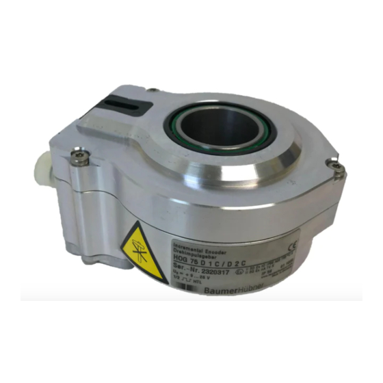
Information Empfehlung für die Produkthandhabung Der inkrementale Drehgeber HOG 75 ist ein opto-elektronisches Prä zi sionsmessgerät, das mit Sorgfalt nur von technisch qualifiziertem Per sonal gehandhabt werden darf. Die zu erwartende Lebensdauer des Gerätes hängt von den Kugellagern ab, die mit einer Dauerschmierung ausgestattet sind. -
Seite 5: General Notes
Information Recommendation for product handling The incremental encoder HOG 75 is an opto electro nic precision measurement device which must be handled with care by skilled personnel only. The expected operating life of the device depends on the ball bearings, which are equipped with a permanent lubrication. -
Seite 6: Betrieb In Explosionsgefährdeten Bereichen
Betrieb in explosionsgefährdeten Bereichen Betrieb in explosionsgefährdeten Bereichen Das Gerät entspricht der Norm EG-Richtlinie 2014/34/EU für explosionsgefährdete Bereiche. Der Einsatz ist gemäß den Gerätekategorien 3 G (Ex-Atmosphäre Gas) und 3 D (Ex-Atmo- sphäre Staub) zulässig. Gerätekategorie 3 G: - Ex-Kennzeichnung: II 3 G Ex nA IIC T4 Gc - Normenkonformität: EN 60079-0:2012... -
Seite 7: Operation In Potentially Explosive Environments
Operation in potentially explosive environments Operation in potentially explosive environments The device complies with the EU standard 2014/34/EU for potentionally explosive atmospheres. It can be used in accordance with equipment categories 3 G (explosive gas atmosphere) and 3 D (explosive dust atmosphere). Equipment category 3 G: II 3 G Ex nA IIC T4 Gc - Ex labeling:... -
Seite 8: Sicherheitshinweise
Sicherheitshinweise Sicherheitshinweise Verletzungsgefahr durch rotierende Wellen Haare und Kleidungsstücke können von rotierenden Wellen erfasst werden. • Vor allen Arbeiten alle Betriebsspannungen ausschalten und Maschinen stillsetzen. Zerstörungsgefahr durch elektrostatische Aufladung Die elektronischen Bauteile im Drehgeber sind empfindlich gegen hohe Spannungen. • Steckkontakte und elektronische Komponenten nicht berühren. •... -
Seite 9: Security Indications
Security indications Security indications Risk of injury due to rotating shafts Hair and clothes may become tangled in rotating shafts. • Before all work switch off all operating voltages and ensure machinery is stationary. Risk of destruction due to electrostatic charge Electronic parts contained in the encoder are sensitive to high voltages. -
Seite 10: Vorbereitung
Vorbereitung / Preparation Vorbereitung Preparation Lieferumfang Scope of delivery Gehäuse Housing Drehmoment-Stützblech Torque support plate Aufnahmeschlitz Slot Stützblech Support plate Durchgehende Hohlwelle Through hollow shaft Klemmring Clamping ring Torx-Schraube M3x12 mm Screw with torx drive M3x12 mm Abdeckhaube Cover Torx-Schraube M3x12 mm Screw with torx drive M3x12 mm Kabelverschraubung M16x1,5 Cable gland M16x1.5... -
Seite 11: Zur Montage Erforderlich (Nicht Im Lieferumfang Enthalten)
Vorbereitung / Preparation Zur Montage erforderlich Required for mounting (nicht im Lieferumfang enthalten) (not included in scope of delivery) Sensorkabel HEK 8, als Zubehör erhältlich, Sensor cable HEK 8, available as accessory, siehe Abschnitt 7.5. see section 7.5. Befestigungen zur Montage des Drehgebers Attachments for mounting the encoder with mit Drehmoment-Stützblech, siehe auch 2.1 * : torque support plate, see also 2.1 * :... -
Seite 12: Erforderliches Werkzeug (Nicht Im Lieferumfang Enthalten)
Vorbereitung / Preparation Erforderliches Werkzeug Required tools (nicht im Lieferumfang enthalten) (not included in scope of delivery) Bei Anbau mit Drehmomentblech 2.1 At mounting with torque support plate 2.1 3 mm 3 mm 5, 10 (2x) und 17 mm 5, 10 (2x) and 17 mm TX 10 TX 10 Bei Anbau mit Drehmomentstift 2.2... -
Seite 13: Montage
Montage / Mounting Montage Mounting Schritt 1 Step 1 TX 10 Schritt 2 Step 2 5.2.1 Version mit Drehmoment-Stützblech 5.2.1 Version with torque support plate 5 mm 3 mm * Siehe Seite 7 oder 8 See page 7 or 8 Motorwelle einfetten! Lubricate motor shaft! Die Antriebswelle sollte einen mög-... -
Seite 14: Version Mit Aufnahmeschlitz Für Drehmomentstift
Montage / Mounting Schritt 2 Step 2 5.2.2 Version mit Aufnahmeschlitz für Dreh- 5.2.2 Version with slot for torque pin momentstift 10 mm Motorwelle einfetten! Lubricate motor shaft! Die Antriebswelle sollte einen mög- The drive shaft should have as less lichst kleinen Rundlauffehler aufwei- runout as possible because this can sen, da dieser zu einem Winkelfehler... -
Seite 15: Schritt 2B
Montage / Mounting 5.2.3.2 Schritt 2b 5.2.3.2 Step 2b 10 mm * Siehe Seite 8 See page 8 Motorwelle einfetten! Lubricate motor shaft! Die Antriebswelle sollte einen mög- The drive shaft should have as less lichst kleinen Rundlauffehler aufwei- runout as possible because this can sen, da dieser zu einem Winkelfehler otherwise result in an angle error, see führen kann, siehe Abschnitt 5.2.3.4. -
Seite 16: Schritt 2C
Montage / Mounting 5.2.3.3 Schritt 2c 5.2.3.3 Step 2c Die Montage der Drehmomentstütze sollte The torque arm should be mounted spielfrei erfolgen. Ein Spiel von beispiels- free from clearance. A play of just weise ±0,03 mm entspricht einem Rund- ±0.03 mm, results in concentricity lauffehler des Drehgebers von 0,06 mm, error of the encoder of 0.06 mm. -
Seite 17: Hinweis Zur Vermeidung Von Messfehlern
Montage / Mounting 5.2.3.4 Hinweis zur Vermeidung von Messfehlern 5.2.3.4 How to prevent measurement errors Für einen einwandfreien Betrieb des To ensure that the encoder operates cor- Drehgebers ist ein korrekter Anbau, ins- rectly, it is necessary to mount it accurately besondere auch der Drehmomentstütze, as described in section 5.1 and 5.2.3.1 to notwendig, wie beschrieben in Abschnitt... -
Seite 18: Schritt 3
Montage / Mounting Schritt 3 Step 3 TX 10 Zul. Anzugsmoment Max. tightening torque = 2-3 Nm Schritt 4 Step 4 TX 10 17 mm * Siehe Seite 7 See page 7 MB010 - 11055616 Baumer_HOG75_II_DE-EN (16A3) -
Seite 19: Schritt 5
Montage / Mounting Schritt 5 Step 5 Ansicht siehe Abschnitt 7.3. View see section 7.3. Zul. Anzugsmoment Max. tightening torque = 2-3 Nm TX 10 17 mm Kabelschirm Cable shield ø5-9 mm 10 * Version mit Anschlusskabel, siehe Abschnitt 7.4, Länge wie bestellt. -
Seite 20: Anbauhinweis
Montage / Mounting Anbauhinweis Mounting instruction Wir empfehlen, den Drehgeber so zu It is recommended to mount the en- montieren, dass der Kabelanschluss coder with cable connection facing keinem direkten Wassereintritt aus- downward and being not exposed to gesetzt ist. water. -
Seite 21: Abmessungen
Abmessungen / Dimensions Abmessungen Dimensions Versionen ohne Hybridlager Version without hybrid bearings 6.1.1 Durchgehende Hohlwelle mit Drehmo- 6.1.1 Through hollow shaft with torque sup- ment-Stützblech und Aufnahmeschlitz port plate and slot for torque pin für Drehmomentstift 6.1.1.1 Klemmring vorne 6.1.1.1 Clamping ring in front (73275) (73275) -
Seite 22: Mit Standard-Stützblech Für Eine Drehmomentstütze Und Aufnahmeschlitz Für Drehmomentstift
Abmessungen / Dimensions Versionen ohne Hybridlager Versions without hybrid bearings 6.1.2 Mit Standard-Stützblech für eine Dreh- 6.1.2 With standard support plate for torque momentstütze und Aufnahmeschlitz arm and slot for torque pin für Drehmomentstift 6.1.2.1 Klemmring vorne 6.1.2.1 Clamping ring in front (73274) (73274) Positive... -
Seite 23: Mit Langem Stützblech Für Eine Drehmomentstütze Und Aufnahmeschlitz Für Drehmomentstift
Abmessungen / Dimensions 6.1.3 Mit langem Stützblech für eine Dreh- 6.1.3 With long support plate for torque momentstütze und Aufnahmeschlitz arm and slot for torque pin für Drehmomentstift 6.1.3.1 Klemmring vorne 6.1.3.1 Clamping ring in front (73270) (73270) ød Positive Drehrichtung Positive rotating... -
Seite 24: Versionen Mit Hybridlager
Abmessungen / Dimensions Versionen mit Hybridlager Versions with hybrid bearings 6.2.1 Mit langem Stützblech für eine Dreh- 6.2.1 With long support plate for torque arm momentstütze 6.2.1.1 Klemmring vorne 6.2.1.1 Clamping ring in front (73287) (73287) Positive Drehrichtung Positive rotating direction MB010 - 11055616 ... -
Seite 25: Elektrischer Anschluss
Elektrischer Anschluss / Electrical connection Elektrischer Anschluss Electrical connection Beschreibung der Anschlüsse Terminal significance Betriebsspannung (für den Drehgeber) +UB; + Voltage supply (for the encoder) Masseanschluss (für die Signale) ; ; GND; 0V Ground (for the signals) Erdungsanschluss (Gehäuse) Earth ground (chassis) Ausgangssignal Kanal 1 K1;... -
Seite 26: Anschlusskabelbelegung (Nur Bei Version Mit Anschlusskabel)
Rosa/Pink = K0 Sensorkabel HEK 8 (Zubehör) Sensor cable HEK 8 (accessory) Es wird empfohlen, das Baumer Hübner Baumer Hübner sensor cable HEK 8 is Sensorkabel HEK 8 zu verwenden oder recommended. As a substitute a shielded ersatzweise ein geschirmtes, paarig ver- twisted pair cable should be used. -
Seite 27: Demontage
Demontage / Dismounting Demontage Dismounting Schritt 1 Step 1 TX 10 17 mm Schritt 2 Step 2 * Siehe Seite 7 oder 8 See page 7 or 8 MB010 - 11055616 Baumer_HOG75_II_DE-EN (16A3) ... -
Seite 28: Version Mit Drehmoment-Stützblech
Demontage / Dismounting Schritt 3 Step 3 8.3.1 Version mit Drehmoment-Stützblech 8.3.1 Version with torque support plate and/ und/oder Aufnahmeschlitz für Drehmo- or slot for torque pin mentstift TX 10 8.3.2 Version mit Stützblech für Anbau einer 8.3.2 Version with support plate for moun- Drehmomentstütze ting a torque arm TX 10... -
Seite 29: Version Mit Aufnahmeschlitz Für Drehmomentstift
Demontage / Dismounting Schritt 4 Step 4 8.4.1 Version mit Drehmoment-Stützblech 8.4.1 Version with torque support plate 3 mm 8.4.2 Version mit Aufnahmeschlitz für Dreh- 8.4.2 Version with slot for torque pin momentstift * Siehe Seite 8 See page 8 MB010 - 11055616 Baumer_HOG75_II_DE-EN (16A3) ... - Seite 30 Demontage / Dismounting 8.3.3 Version mit Stützblech für Anbau einer 8.3.3 Version with support plate for moun- Drehmomentstütze ting a torque arm MB010 - 11055616 Baumer_HOG75_II_DE-EN (16A3)
-
Seite 31: Zubehör
Zubehör / Accessories Zubehör Accessories • Drehmomentstütze, • Torque arm, als Zubehör erhältlich, available as accessory, Bestellnummer (Länge L): order number (length L): Standardversion: Standard version: 11043628 (67-70 mm) 11043628 (67-70 mm) 11004078 (125 (±5) mm, 11004078 (125 (±5) mm, can be kürzbar auf ≥71 mm) shortened to ≥71 mm) 11083179... -
Seite 32: Technische Daten
Technische Daten Technische Daten 10.1 Technische Daten - elektrisch • Betriebsspannung: 9...26 VDC (HTL, TTL - Version R) 5 VDC ±5 % (TTL) • Betriebsstrom ohne Last: ≤100 mA • Impulse pro Umdrehung: 250...2500 (Je nach Bestellung) • Phasenverschiebung: 90° ±20° •... -
Seite 33: Technical Data
Technical data Technical data 10.1 Technical data - electrical ratings • Voltage supply: 9...26 VDC (HTL, TTL - version R) 5 VDC ±5 % (TTL) • Consumption w/o load: ≤100 mA • Pulses per revolution: 250...2500 (As ordered) • Phase shift: 90° ±20° •... -
Seite 34: Anhang: Eu-Konformitätserklärung
Signature/nom/fonction Baumer_HOGx_OGx_POGx_FOGx_HMI_DE-EN-FR_CoC_81201236.docm/kwe Baumer Hübner GmbH P.O. Box 126943 ∙ D-10609 Berlin ∙ Max-Dohrn-Str. 2+4 ∙ D-10589 Berlin Phone +49 (0)30 69003-0 ∙ Fax +49 (0)30 69003-104 ∙ info@baumerhuebner.com ∙ www.baumer.com Sitz der Gesellschaft / Registered Office: Berlin, Germany ∙ Geschäftsführer / Managing Director: Dr. Oliver Vietze, Dr. Johann Pohany Handelsregister / Commercial Registry: AG Charlottenburg HRB 96409 ∙... - Seite 35 MB010 - 11055616 Baumer_HOG75_II_DE-EN (16A3)
- Seite 36 Baumer Hübner GmbH Originalsprache der Anleitung ist Deutsch. P.O. Box 12 69 43 · 10609 Berlin, Germany Technische Änderungen vorbehalten. Phone: +49 (0)30/69003-0 · Fax: +49 (0)30/69003-104 Original language of this instruction is German. info@baumerhuebner.com · www.baumer.com/motion Technical modifications reserved.