Herunterladen Diese Seite drucken

Werbung

Verfügbare Sprachen

Verfügbare Sprachen

HWK 332 Econ5S
Hydro-Tower
mit WPM
Bestell-Nr. / Order no. / N
Hydro tower
with HPM
o
de commande : 452162.66.10
Montage- und
Gebrauchsanweisung
Installation and
Operating Instructions
Instructions d'installation
et d'utilisation
Tour hydraulique
combinée avec
gestionnaire de PAC
FD 9504

Werbung

Fehlerbehebung

loading

Inhaltszusammenfassung für Dimplex HWK 332 Econ5S

  • Seite 1 HWK 332 Econ5S Montage- und Gebrauchsanweisung Installation and Operating Instructions Instructions d‘installation et d’utilisation Hydro-Tower Hydro tower Tour hydraulique mit WPM with HPM combinée avec gestionnaire de PAC Bestell-Nr. / Order no. / N de commande : 452162.66.10 FD 9504...
  • Seite 3: Inhaltsverzeichnis

    HWK 332 Econ5S Inhaltsverzeichnis Bitte sofort lesen ........................DE-2 1.1 Wichtige Hinweise ..........................DE-2 1.2 Gesetzliche Vorschriften und Richtlinien ..................... DE-2 Verwendungszweck des Hydro-Towers................... DE-3 2.1 Anwendungsbereich ..........................DE-3 2.2 Allgemeine Eigenschaften ........................DE-3 Lieferumfang..........................DE-3 3.1 Grundgerät............................DE-3 3.2 Schaltkasten ............................DE-3 3.3 Wärmepumpenmanager ........................
  • Seite 4: Bitte Sofort Lesen

    HWK 332 Econ5S Bitte sofort lesen 1.2 Gesetzliche Vorschriften und Richtlinien 1.1 Wichtige Hinweise Diese Wärmepumpe ist gemäß Artikel 1, Abschnitt 2 k) der EG- Richtlinie 2006/42/EC (Maschinenrichtlinie) für den Gebrauch im ACHTUNG! häuslichen Umfeld bestimmt und unterliegt damit den Anforde- Vor Öffnen des Gerätes ist sicherzustellen, dass alle Stromkreise...
  • Seite 5: Verwendungszweck Des Hydro-Towers

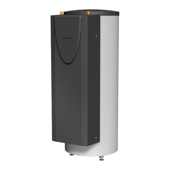
    HWK 332 Econ5S Verwendungszweck des Lieferumfang Hydro-Towers 3.1 Grundgerät 2.1 Anwendungsbereich Hydraulische Komponenten  Doppelt differenzdruckloser Verteiler Der Hydro-Tower bildet die Schnittstelle zwischen einer nicht re-  Pufferspeicher 100 Liter versiblen Wärmepumpe und der Wärmeverteilung im Gebäude.  Ungemischter Heizkreis incl. geregelter Umwälzpumpe Der Hydro-Tower beinhaltet alle hydraulischen Komponenten die (stufenlos bzw.
  • Seite 6: Zubehör

    HWK 332 Econ5S Zubehör Transport Der Transport zum endgültigen Aufstellungsort sollte mit der Pa- 4.1 Fernbedienung lette erfolgen. Das Grundgerät bietet einerseits die Transport- möglichkeit mit Hubwagen, Sackkarre o.Ä.. Als Komforterweiterung ist im Sonderzubehör eine Fernbe- dienstation erhältlich. Bedienung und Menüführung sind iden- tisch mit denen des Wärmepumpenmanagers.
  • Seite 7: Aufstellung

    HWK 332 Econ5S Aufstellung Montage 6.1 Allgemein 7.1 Allgemein Das Gerät muss in einem frostfeien und trockenen Raum auf Am Hydro-Tower sind folgende Anschlüsse herzustellen. einer ebenen, glatten und waagerechten Fläche aufgestellt wer-  Vor-/ Rücklauf Wärmepumpe den. Der Hydro-Tower muss so aufgestellt sein, dass Wartungs- ...
  • Seite 8: Heizungsseitiger Anschluss

    7.2 Heizungsseitiger Anschluss 7.3 Temperaturfühler Die heizungsseitigen Anschlüsse am Hydro-Tower sind mit 7.3.1 Hydro-Tower HWK 332 Econ5S 1 1/4" flachdichtendem Außengewinde versehen. Beim An- schluss muss an den Übergängen mit einem Schlüssel gegenge- Folgende Temperaturfühler sind bereits eingebaut bzw. müssen halten werden.
  • Seite 9: Montage Der Anlegefühler

    Abdeckkappe) ist ein Kabelkanal eingearbeitet, der es er- möglicht die Elektroleitungen unter der oberen Abdeckung zu verlegen (von der Speicherrückseite zur Anschlussseite vorne). HINWEIS Beim HWK 332 Econ5S sind zwei Verbindungsleitungen (< 25 V / 230 V) zwischen dem Wärmepumpenmanager und der Wärmepumpe zu verlegen.
  • Seite 10: Inbetriebnahme

    HWK 332 Econ5S Inbetriebnahme In beiden Fällen sollte die Reinigungsflüssigkeit Raumtempera- tur haben. Es ist empfehlenswert, den Wärmetauscher entgegen der normalen Durchflussrichtung zu spülen. 8.1 Allgemein Um zu verhindern, dass säurehaltiges Reinigungsmittel in den Heizungsanlagenkreislauf gelangt, empfehlen wir, das Spülgerät Um eine ordnungsgemäße Inbetriebnahme zu gewährleisten,...
  • Seite 11: Geräteinformation

    HWK 332 Econ5S 12 Geräteinformation Typ- und Verkaufsbezeichnung HWK 332 Econ5S Bauform Hydro Tower mit doppelt differenzdrucklosem Verteiler mit Ausführung Regler Schutzart nach EN 60529 IP 20 Aufstellungsort Innen Technische Daten Wärmeerzeugung extern Pufferspeicher Nenninhalt Liter zul. Betriebstemperatur °C maximaler Betriebsüberdruck elektrische Rohrheizung 2, 4 bzw.
  • Seite 12 HWK 332 Econ5S DE-10 452162.66.10 FD 9504...
  • Seite 13 HWK 332 Econ5S Table of contents Please read immediately......................EN-2 1.1 Important information........................... EN-2 1.2 Legal regulations and guidelines ......................EN-2 Purpose of the Heat Pump ......................EN-3 2.1 Application ............................EN-3 2.2 General properties ..........................EN-3 Scope of supply.......................... EN-3 3.1 Basic device............................
  • Seite 14: Please Read Immediately

    HWK 332 Econ5S Please read 1.2 Legal regulations and immediately guidelines This heat pump is designed for use in a domestic environment according to Article 1, Paragraph 2 k) of EC directive 2006/42/EC 1.1 Important information (machinery directive) and is thus subject to the requirements of EC directive 2006/95/EC (low-voltage directive).
  • Seite 15: Purpose Of The Heat Pump

    (HWK 332 Econ5S). 3.3 Heat pump manager The integrated heat pump manager (HWK 332 Econ5S) is a con- venient electronic regulation and control device. It controls and monitors the entire heating system based on the external tem- perature, as well as domestic hot water preparation and safety systems.
  • Seite 16: Accessories

    HWK 332 Econ5S Accessories Transport A pallet should be used to transport the heat pump to its final in- 4.1 Remote control stallation location. The basic device can be transported with a lift truck, a pushcart or similar. A remote control adds convenience and is available as a special accessory.
  • Seite 17: Installation

    Setup and installation must be performed by an authorised spe- NOTE cialist company. When removing the device cover (HWK 332 Econ5S versions only), it must be taken into account that the length of the connecting cable between the control panel in the device cover and the controller on the operator panel is only 1.5m.
  • Seite 18: Heating System Connection

    7.2 Heating system connection 7.3 Temperature sensor The heating system connections on the hydro tower have a 1 1/ 7.3.1 Hydro tower HWK 332 Econ5S 4" flat-sealing external thread. A spanner must be used to firmly grip the transitions when making the connections.
  • Seite 19: Mounting The External Temperature Sensor

    (from the rear of the cylinder to the front/connection side). NOTE To use the HWK 332 Econ5S, two connecting cables (< 25 V / 230 V) must be routed between the heat pump managr and the heat pump. NOTE Further information on the wiring of the heat pump manager is available in the electrical documentation.
  • Seite 20: Start-Up

    HWK 332 Econ5S Start-up In either case, the cleaning fluid should be at room temperature. We recommend flushing the heat exchanger in the direction op- posite to the normal flow direction. 8.1 General To prevent acidic cleaning agents from entering the heating sys-...
  • Seite 21: Device Information

    HWK 332 Econ5S 12 Device information Type and order code HWK 332 Econ5S Design Hydro tower with dual differential pressureless manifold and Model controller Degree of protection in accordance with EN 60529 IP 20 Installation location Indoors Technical data Heat generation...
  • Seite 22 HWK 332 Econ5S EN-10 452162.66.10 · FD 9504...
  • Seite 23 HWK 332 Econ5S Table des matières À lire immédiatement !....................... FR-2 1.1 Remarques importantes ........................FR-2 1.2 Dispositions légales et directives......................FR-2 Utilisation de la tour hydraulique combinée................FR-3 2.1 Domaine d’utilisation..........................FR-3 2.2 Généralités ............................FR-3 Fournitures ..........................FR-3 3.1 Appareil de base...........................FR-3 3.2 Boîtier électrique...........................FR-3...
  • Seite 24: Lire Immédiatement

    HWK 332 Econ5S À lire immédiatement ! 1.2 Dispositions légales et directives 1.1 Remarques importantes Cette pompe à chaleur est conçue pour une utilisation dans un environnement domestique selon l'article 1 (paragraphe 2 k) de ATTENTION ! la directive CE 2006/42/CE (directive relative aux machines) et Avant d’ouvrir l’appareil, s'assurer que tous les circuits électriques sont...
  • Seite 25: Utilisation De La Tour Hydraulique Combinée

    Econ5S). 3.3 Gestionnaire de pompe à chaleur Le gestionnaire de pompe à chaleur intégré (HWK 332 Econ5S) est un appareil de commande et de régulation électronique facile à utiliser. Il commande et surveille l’ensemble de l’installation de chauffage en fonction de la température extérieure, la production d’eau chaude sanitaire et les dispositifs de sécurité.
  • Seite 26: Accessoires

    HWK 332 Econ5S Accessoires Transport Le transport vers l'emplacement définitif doit de préférence s'ef- 4.1 Télécommande fectuer sur une palette. L’appareil de base peut être transporté avec un chariot élévateur, diable ou toute solution équivalente. Une station de télécommande est disponible comme accessoire spécial pour améliorer le confort.
  • Seite 27: Installation

    être effectuées par une entreprise spécialisée agréée ! Lors du démontage du capot de l'appareil (seulement pour les versions HWK 332 Econ5S), tenir compte du fait que le câble de raccordement - entre l'unité de commande située dans le capot de l'appareil et le régulateur sur le panneau de commande - ne mesure pas plus de 1,5 m.
  • Seite 28: Raccordement Côté Chauffage

    HWK 332 Econ5S 7.2 Raccordement côté chauffage Débit minimum d'eau de chauffage Le distributeur double sans pression différentielle assure le débit Les raccordements du chauffage à la tour hydraulique combinée minimum d’eau de chauffage de la pompe à chaleur quel que soit sont dotés deraccords à...
  • Seite 29: Montage Des Sondes D'applique

    HWK 332 Econ5S 7.3.2 Courbes caractéristiques de la 7.3.4 Montage des sondes d'applique sonde Le montage des sondes d'applique est nécessaire uniquement si ces sondes sont comprises dans les fournitures de la pompe à chaleur, mais non montées. Température en °C NTC-2 en k...
  • Seite 30: Branchements Électriques

    à la zone de raccordement à l'avant). REMARQUE Deux câbles de raccordement (< 25 V / 230 V) doivent être raccordés pour HWK 332 Econ5S entre le gestionnaire de pompe à chaleur et la pompe à chaleur. REMARQUE D'autres informations sur le câblage du gestionnaire de pompe à...
  • Seite 31: Nettoyage / Entretien

    HWK 332 Econ5S Nettoyage / entretien 9.3 Anode anticorrosion L’anode anticorrosion montée dans le ballon d’eau chaude doit 9.1 Entretien être contrôlée électriquement à intervalles réguliers et tous les deux ans au minimum après la mise en service de la pompe à...
  • Seite 32: Informations Sur Les Appareils

    HWK 332 Econ5S 12 Informations sur les appareils Désignation technique et commerciale HWK 332 Econ5P Forme Tour hydraulique combinée équipée d’un distributeur double Version sans pression différentielle avec gestionnaire de PAC Degré de protection selon EN 60529 IP 20 Emplacement de montage à...
  • Seite 33: Anhang / Appendix / Annexes

    HWK 332 Econ5S Anhang / Appendix / Annexes Maßbilder / Dimension Drawings / Schémas cotés..............A-II 1.1 Maßbild / Dimension Drawing / Schémas coté ..................A-II Diagramme / Diagrams / Diagrammes ..................A-III 2.1 Kennlinien / Characteristic Curves / Courbes caractéristiques.............. A-III Hydraulische Einbindungsschema / Hydraulic integration diagram / Schéma d’intégration hydrauliques ..................
  • Seite 34: Maßbilder / Dimension Drawings / Schémas Cotés

    HWK 332 Econ5S 1 Maßbilder / Dimension Drawings / Schémas cotés 1.1 Maßbild / Dimension Drawing / Schémas coté A-II 452162.66.10 · FD 9504...
  • Seite 35: Diagramme / Diagrams / Diagrammes

    HWK 332 Econ5S 2 Diagramme / Diagrams / Diagrammes 2.1 Kennlinien / Characteristic Curves / Courbes caractéristiques 452162.66.10 · FD 9504 A-III...
  • Seite 36: Hydraulische Einbindungsschema / Hydraulic Integration Diagram / Schéma D'intégration Hydrauliques

    HWK 332 Econ5S 3 Hydraulische Einbindungsschema / Hydraulic integration diagram / Schéma d’intégration hydrauliques 3.1 Monoenergetische Wärmepumpenheizungsanlage mit einem Heizkreis, Puffer- und Warmwasserspeicher / Mono energy heat pump heating system with one heating circuit, buffer tank and hot water cylinder / Installation de chauffage par pompe à...
  • Seite 37: Elektroschema Für Monoenergetische Wärmepumpenheizungsanlage Mit Einem Heizkreis, Puffer- Und

    HWK 332 Econ5S 3.2 Elektroschema für monoenergetische Wärmepumpenheizungsanlage mit einem Heizkreis, Puffer- und Warmwasserspeicher / Electical circuit diagram for a mono energy system with one heating circuits, buffer tank and hot water cylinder / Schéma électrique pour une installation mono-énergétique avec un circuits de chauffage, ballons tampon et d'eau chaude sanitaire 452162.66.10 ·...
  • Seite 38: De Chauffage, Ballons Tampon Et D'eau Chaude Sanitaire

    HWK 332 Econ5S 3.3 Monoenergetische Wärmepumpenheizungsanlage mit drei Heizkreise, Puffer- und Warmwasserspeicher / Mono energy heat pump heating system with three heating circuits, buffer tank and hot water cylinder / Installation de chauffage par pompe à chaleur mono-énergétique avec trois circuits de chauffage, ballons tampon et d'eau chaude sanitaire A-VI 452162.66.10 ·...
  • Seite 39: Elektroschema Für Monoenergetische Wärmepumpenheizungsanlage Mit Drei Heizkreise, Puffer- Und

    HWK 332 Econ5S 3.4 Elektroschema für monoenergetische Wärmepumpenheizungsanlage mit drei Heizkreise, Puffer- und Warmwasserspeicher / Electical circuit diagram for a mono energy system with three heating circuits, buffer tank and hot water cylinder / Schéma électrique pour une installation mono-énergétique avec trois circuits de chauffage, ballons tampon et d'eau chaude sanitaire 452162.66.10 ·...
  • Seite 40: Legende / Legend / Légende

    HWK 332 Econ5S 3.5 Legende / Legend / Légende Absperrventil Shutoff valve Robinet d’arrêt Dreiwegemischer Three-way mixer Mélangeur 3 voies Umwälzpumpe Circulating pump Circulateur Ausdehnungsgefäß Expansion vessel Vase d´expansion Vanne commandée par Raumtemperaturgesteuertes Ventil Room temperature-controlled valve température ambiante Absperrventil mit Rückschlagventil Shutoff valve with check valve Robinet d’arrêt avec clapet anti-retour...
  • Seite 41 HWK 332 Econ5S 452162.66.10 · FD 9504 A-IX...
  • Seite 42 HWK 332 Econ5S 452162.66.10 · FD 9504...
  • Seite 43 HWK 332 Econ5S 452162.66.10 · FD 9504 A-XI...
  • Seite 44 Garantiebedingungen und Kundendienstadresse siehe Mon- Irrtümer und Änderungen vorbehalten. tage- und Gebrauchsanweisung Wärmepepumpe. Subject to alterations and errors. Sous réserve d’erreurs et modifications. For the terms of the guarantee and after-sales service addres- ses, please refer to the Installation and Operating Instructions for Heat Pumps.