Herunterladen Diese Seite drucken

Axis A1001 Installationsanleitung

Network door controller
Vorschau ausblenden Andere Handbücher für A1001:

Werbung

Verfügbare Sprachen
  • DE

Verfügbare Sprachen

  • DEUTSCH, seite 87
AXIS A1001 Network Door Controller
Installation Guide

Werbung

loading

Inhaltszusammenfassung für Axis A1001

  • Seite 1 AXIS A1001 Network Door Controller Installation Guide...
  • Seite 3 English France: Français Deutschland: Deutsch Italia: Italiano España: Español...
  • Seite 4 Search by product, category, or phrase • report problems to Axis support staff by logging in to damages in connection with the furnishing, performance or use of this material. This product is only to be used for your private support area •...
  • Seite 5 (PS2) rated output power limited to This list of supported readers is subject to change without ≤100 W according to IEC/EN 62368-1 notice. Contact your Axis reseller for information about Disposal and recycling supported readers. When this product has reached the end of its useful life, This product is compatible with UL Listed Wiegand access dispose of it according to local laws and regulations.
  • Seite 6 6142CKP0100; RWKL550: 6171BK4000000, 6171BK4000009, 6171BK4000014, 6171BK4000214, 6171BK4000500, 6171BK4040Z14, 6171BK4060000, 6171BK4060209, 6171BK4060Z09, 6171BK4061000, 6171BKM000000, 6171BKM000200, 6171BKM000300, 6171BKM040400; RWKLB575: 6181BK4000000, 6181BK4000009, 6181BK4000014, 6181BK4000022, 6181BK406C009; HID Smartid®: 8031DSAP HID pivClass® R10-H: 900LHRNAK00000, 900LHRTAK00000, 900NHRNAK00000, 900NHRTAK00000, 900PHRNAK00000, 900PHRTAK00000, 910LHRNAK00000, 910LHRTAK00000, 910NHRNAK00000, 910NHRTAK00000, 910PHRNAK00000, 910PHRTAK00000, 920LHRNAK00000, 920LHRTAK00000, 920NHRNAK00000, 920NHRTAK00000, 920PHRNAK00000, 920PHRTAK00000, 921LHRNAK00000, 921LHRTAK00000, 921NHRNAK00000, 921NHRTAK00000,...
  • Seite 7 • When the Axis product has reached the end of its useful life, dispose of it according to local laws and regulations. The product should not be disposed of together with household or commercial waste. See Disposal and recycling 5.
  • Seite 8 • Wall and Ceiling Mount If using a junction box to mount the Axis product, the junction box shall be UL Listed. • Assign an IP Address The functionality of AXIS Camera Management, see page 38, has not been evaluated by UL.
  • Seite 9: Safety Information

    AXIS A1001 Network Door Controller Safety information Hazard levels DANGER Indicates a hazardous situation which, if not avoided, will result in death or serious injury. WARNING Indicates a hazardous situation which, if not avoided, could result in death or serious injury.
  • Seite 10: Safety Instructions

    • When transporting the Axis product, use the original packaging or equivalent to prevent damage to the product. Battery The Axis product uses a 3.0 V CR2032 lithium battery as the power supply for its internal real-time clock (RTC). Under normal conditions this battery will last for a minimum of five years.
  • Seite 11 WARNING • Risk of explosion if the battery is incorrectly replaced. • Replace only with an identical battery or a battery which is recommended by Axis. • Dispose of used batteries according to local regulations or the battery manufacturer's instructions.
  • Seite 13: Installation Steps

    AXIS A1001 Network Door Controller Installation Guide - Full Reference This full reference installation guide provides instructions for how to install AXIS A1001 Network Door Controller on your network. • For a quick reference guide, see the printed AXIS A1001 Installation Guide – Quick Reference that is included in the package contents.
  • Seite 14: Recommended Tools

    AXIS A1001 Network Door Controller • Printed materials AXIS A1001 Installation Guide – Quick Reference Extra serial number label (2x) AVHS Authentication key Recommended Tools • Drill – if mounting on wall or ceiling • Screwdriver – if mounting on wall or ceiling •...
  • Seite 15 AXIS A1001 Network Door Controller Front and back: Cover Cover screw Cover removal slot Base DIN clip – upper Tampering alarm switch – back DIN clip – lower Part number (P/N) & Serial number (S/N)
  • Seite 16: Inhaltsverzeichnis

    AXIS A1001 Network Door Controller I/O interface: Reader data connector (READER DATA 1) 10 Reader data connector (READER DATA 2) Reader I/O connector (READER I/O 1) Reader I/O connector (READER I/O 2) Door connector (DOOR IN 1) Door connector (DOOR IN 2)
  • Seite 17 AXIS A1001 Network Door Controller LED indicators, buttons and other hardware: Power LED indicator Status LED indicator Network LED indicator Reader 2 LED indicator (not used) Reader 1 LED indicator (not used) Tampering alarm pin header – front (TF) Tampering alarm pin header – back (TB)
  • Seite 18: Led Indicators

    AXIS A1001 Network Door Controller LED Indicators Color Indication Network Green Steady for connection to a 100 MBit/s network. Flashes for network activity. Amber Steady for connection to a 10 MBit/s network. Flashes for network activity. Unlit No network connection.
  • Seite 19 AXIS A1001 Network Door Controller Door Connectors Two 4-pin terminal blocks for connecting door monitoring devices and request to exit (REX) devices. For specifications, see page 24. Auxiliary Connector 4-pin configurable I/O terminal block. Use with external devices, in combination with, for example tampering alarms, event triggering and alarm notifications.
  • Seite 20: Operating Conditions

    10–30 V DC, max 26 W Power Output Conversion (W to A) If the device connecting to the Axis product only has an ampere (A) rating, the following method can be used for conversion to watts (W). The total maximum output load of the Axis product depends on the power source:...
  • Seite 21 14 W 10–30 V DC The voltage on the Axis product’s power outputs is 12 V DC (except for the Auxiliary Connector which has a voltage of 3.3 V DC). If your connecting device has a maximum ampere rating of for example 0.3 A, the following conversion gives the power in watts (W):...
  • Seite 22: Reader Data Connector (Reader Data 1)

    AXIS A1001 Network Door Controller Endurance Standby Power Wire Area NO TICE TICE TICE Each wire shall have an conductor cross-sectional area that corresponds to an conductor gauge range of AWG 28–16 (CSA) or AWG 22–14 (cUL/UL). Select cables in compliance with your local regulations.
  • Seite 23: Reader I/O Connector (Reader I/O 1)

    AXIS A1001 Network Door Controller Function Notes RS485 For full duplex RS485 For half duplex RS485 RS485 For full duplex RS485 For half duplex RS485 Wiegand For Wiegand D0 (Data 0) D1 (Data 1) Important The RS485 ports have a fixed baudrate of 9600 Bit/s.
  • Seite 24: Door Connector (Door In 1)

    AXIS A1001 Network Door Controller 3–6 Configurable Digital input — Connect to pin 1 to 0 to max 40 V DC (Input or activate, or leave floating (unconnected) Output) to deactivate. Digital output — Connect to pin 1 to 0 to max 40 V DC, open...
  • Seite 25: Auxiliary Connector (Aux)

    AXIS A1001 Network Door Controller Auxiliary Connector 4-pin configurable I/O terminal block for: • Auxiliary power (DC output) • Digital Input • Digital Output • 0 V DC (-) For an example connection diagram, see Connection Diagrams on page Function...
  • Seite 26 AXIS A1001 Network Door Controller Function Notes Specifications 0 V DC 0 V DC (-) For powering controller when not using DC input 10–30 V DC, max 26 W Power over Ethernet. Max load on outputs = Note: This pin can only be used as 14 W power in.
  • Seite 27 AXIS A1001 Network Door Controller Power & Relay Connector 6-pin terminal block with built-in relay for: • External devices • Auxiliary power (DC output) • 0 V DC (-) Connect locks and loads to the pins according to the hardware pin chart generated through the hardware configuration.
  • Seite 28: Connection Diagrams

    AXIS A1001 Network Door Controller door controller is removed from the wall or ceiling. For information about how to configure alarms and events, see the User Manual. Connection Diagrams Connect devices according to the hardware pin chart generated through the hardware configuration.
  • Seite 29: Install The Hardware

    The Axis product shall be installed within the secured area. The Axis product, whether it is installed as a single door controller or in a system of door controllers, shall not limit or weaken the intended use of the devices connected to it.
  • Seite 30 • Wireless locks are not sold and distributed by Axis Communications. For support and training related to wireless systems, contact relevant manufacturers' partner. • The Axis product is considered standalone, and does not require constant connection to a computer for proper operation. The use of a connected computer is for local programming, downloading, and supplemental monitoring purposes only.
  • Seite 31: Din Rail Mount

    AXIS A1001 Network Door Controller Base Screw hole (4x) 6. Connect the cables. See page 32. DIN Rail Mount 1. If required, install a DIN rail (not included). 2. If required, remove the cover screw, insert a slotted screwdriver into the cover removal slot and remove the cover.
  • Seite 32: Connect The Cables

    2.5 mm (0.1 in). If the base is bent, the cover will not close. 8. Connect the cables. See page 32. Connect the Cables CAUTION Disconnect power before connecting any wires to the Axis product. Never make connections while power is applied to the product.
  • Seite 33 AXIS A1001 Network Door Controller NO TICE TICE TICE • The product shall be connected using a shielded network cable (STP). All cables connecting the product to the network shall be intended for their specific use. Make sure that the network devices are installed in accordance with the manufacturer’s instructions.
  • Seite 34 AXIS A1001 Network Door Controller 3. Strip the cables and wires as required using a crimp tool. 4. Connect the wires between the door controller and the locks, doors and other devices. For more information about the connectors and their specifications, see page 18 and page 22.
  • Seite 35 AXIS A1001 Network Door Controller • For information about how to connect other wires, such as power wires to locks, readers and other devices, see the manufacturers’ instructions. 5. Collect all the wires neatly and secure them using the supplied cable ties.
  • Seite 36: Access The Product

    To assign an IP address, see page 37. • To set the root password, see page 40. How to access the product from a browser 1. Start a web browser. 2. Enter the IP address or host name of the Axis product in the browser’s address field.
  • Seite 37: Assign An Ip Address

    AXIS A1001 Network Door Controller If you do not know the IP address, use AXIS IP Utility to locate the product on the network. For information about how to discover and assign an IP address, see Assign an IP Address. This information is also available from the support pages at axis.com/support Note To show Bonjour as a browser bookmark, go to Safari >...
  • Seite 38 AXIS A1001 Network Door Controller Note that the computer running AXIS IP Utility must be on the same network segment (physical subnet) as the Axis product. Automatic Discovery 1. Check that the Axis product is connected to the network and has powered up.
  • Seite 39 7. For information about how to set the password, see page 40. Assign IP Addresses in Multiple Devices AXIS Camera Management speeds up the process of assigning IP addresses to multiple devices by suggesting IP addresses from a specified range.
  • Seite 40 Utilities. How to set the root password To access the Axis product, you must set the password for the default administrator user root. This is done in the Configure Root Password dialog, which opens when the product is accessed for the first time.
  • Seite 41 Configure the hardware in the Hardware Configuration pages before installing the product. Doors, floors, locks and other devices can be connected to the Axis product before completing the hardware configuration. However, the connection of devices will be easier if you complete the hardware configuration first.
  • Seite 42: Connect The Hardware

    I/O Relay Module. Go to A9188 web interface > Preferences > Additional device configuration > Basic setup > Users > Add > User setup. Note Max 2 AXIS 9188 Network I/O Relay Modules can be configured with each A1001 Network Door Controller...
  • Seite 43 AXIS A1001 Network Door Controller 1. In A1001, go to Setup > Hardware Configuration and click Start new hardware configuration. 2. Enter a name for the Axis product. 3. Select Elevator control to include an AXIS A9188 Network I/O Relay Module and click Next 4.
  • Seite 44: How To Reset To Factory Default Settings

    Maintenance Instructions To keep the access control system running smoothly, Axis recommends regular maintenance of the access control system, including door controllers and connected devices. Do maintenance at least once a year. The suggested maintenance procedure includes, but is not limited to, the following steps: •...
  • Seite 45: Further Information

    For the latest version of this document, see axis.com • The user manual is available at axis.com • To check if there is updated firmware available for your product, see axis.com/support • For useful online trainings and webinars, see axis.com/academy Warranty information For information about Axis’...
  • Seite 47: Informations Sur La Sécurité

    AXIS A1001 Network Door Controller Informations sur la sécurité Niveaux de risques DANGER Indique une situation dangereuse qui, si elle n'est pas évitée, entraînera le décès ou des blessures graves. AVERTISSEMENT Indique une situation dangereuse qui, si elle n'est pas évitée, pourrait entraîner le décès ou des blessures graves.
  • Seite 48: Consignes De Sécurité

    AXIS A1001 Network Door Controller Consignes de sécurité AVERTISSEMENT Le produit Axis doit être installé par un professionnel qualifié et conformément aux lois et règlementations locales en vigueur. A A A VIS • Le produit Axis doit être utilisé conformément aux lois et règlements locaux.
  • Seite 49 AXIS A1001 Network Door Controller Batterie Le produit Axis utilise une batterie au lithium CR2032 3,0 V comme alimentation de son horloge en temps réel interne (RTC). Dans des conditions normales, cette batterie a une durée de vie minimale de cinq ans.
  • Seite 51: Procédures D'installation

    AXIS A1001 sur votre réseau. • Pour un guide de référence rapide, reportez-vous à la version imprimée du Guide d'installation – Référence rapide AXIS A1001 contenu dans l'emballage. Ce guide de référence rapide est également disponible sur www.axis.com •...
  • Seite 52: Outils Recommandés

    AXIS A1001 Network Door Controller • Documents imprimés Guide d'installation AXIS A1001 - Référence rapide Étiquette supplémentaire de numéro de série (x2) Clé d'authentification AVHS Outils recommandés • Perceuse - en cas de fixation au mur ou au plafond •...
  • Seite 53 AXIS A1001 Network Door Controller Avant et arrière : Couvercle Vis du couvercle Fente de retrait du couvercle Socle Clip DIN - supérieur Commutateur d'alarme de détérioration – arrière Clip DIN – inférieur Référence (P/N) et numéro de série (S/N).
  • Seite 54 AXIS A1001 Network Door Controller Interface E/S : Connecteur de données du lecteur (READER DATA 1) 10 Connecteur de données du lecteur (READER DATA 2) Connecteur E/S du lecteur (READER I/O 1) Connecteur E/S du lecteur (READER I/O 2) Connecteur de porte (DOOR IN 1)
  • Seite 55 AXIS A1001 Network Door Controller Voyants DEL, boutons et autre matériel : Voyant DEL d’alimentation Voyant d’état Voyant DEL réseau Voyant DEL du lecteur 2 (non utilisé) Voyant DEL du lecteur 1 (non utilisé) Bloc de connexion de l'alarme de détérioration – avant (TF) Bloc de connexion de l'alarme de détérioration –...
  • Seite 56: Led Indicators

    AXIS A1001 Network Door Controller LED Indicators Color Indication Network Green Steady for connection to a 100 MBit/s network. Flashes for network activity. Amber Steady for connection to a 10 MBit/s network. Flashes for network activity. Unlit No network connection.
  • Seite 57 AXIS A1001 Network Door Controller • Sortie numérique – Permet de connecter des beepers et des voyants du lecteur par exemple Pour les caractéristiques, consultez page 61. Connecteurs de portes Deux blocs terminaux à 4 broches pour le branchement des périphérique de contrôle des portes et les périphériques de demande de sortie (REX).
  • Seite 58: Caractéristiques Techniques

    • Réinitialisation du produit aux paramètres d’usine par défaut. Cf. page 84. • Connexion au service du Système d'hébergement vidéo AXIS ou au service AXIS Internet Dynamic DNS. Pour plus d'informations sur ces services, reportez-vous au Manuel de l'utilisateur. Caractéristiques techniques Conditions d'utilisation L'appareil Axis est uniquement destiné...
  • Seite 59 10 à 30 V CC 14 W La tension en sortie d'alimentation du produit Axis est de 12 V CC (à l'exception du connecteur auxiliaire qui a une tension de 3,3 V CC). Si votre dispositif de liaison a une intensité nominale de, par exemple, 0,3 A, la conversion suivante vous indique la puissance en watt (W).
  • Seite 60 AXIS A1001 Network Door Controller Niveaux de performance pour le contrôle d'accès Cette section contient des informations sur le niveau de performance requis pour la conformité UL 294. Fonction Niveau Essai d'attaque destructrice Sécurité de la ligne Résistance Alimentation de veille Zone de câble...
  • Seite 61 AXIS A1001 Network Door Controller Connecteur de données du lecteur Bloc terminal à 6 broches prenant en charge les protocoles RS485 et Wiegand pour la communication avec le lecteur. Les ports RS485 prennent en charge : • RS485 semi-duplex sur deux fils •...
  • Seite 62: Connecteur De Porte (Door In 1)

    AXIS A1001 Network Door Controller Fonction Broche Notes Caractéristiques 0 V CC 0 V CC (-) Sortie CC Alimentation du matériel auxiliaire. 12 V CC Remarque : cette broche ne peut Charge maximale = 300 mA être utilisée que comme sortie d’alimentation.
  • Seite 63: Connecteur Auxiliaire (Aux)

    AXIS A1001 Network Door Controller Fonction Broche Notes Caractéristiques 1, 3 0 V CC 0 V CC (-) Entrée 2, 4 Pour la communication avec le moniteur 0 à 40 V CC max. de porte. Entrée numérique — Raccordez-la respectivement à la broche 1 ou 3 pour activer ou laisser flotter (déconnectée)
  • Seite 64: Connecteur D'alimentation (Dc In)

    AXIS A1001 Network Door Controller 3–4 Configurable Entrée numérique — Connectez-la 0 à 40 V CC max. (entrée ou à la broche 1 pour l’activer ou sortie) laissez-la flotter (déconnectée) pour la désactiver. Sortie numérique — Connectez-la 0 à 40 V CC max., drain à...
  • Seite 65: Connecteur Du Verrou D'alimentation (Lock)

    AXIS A1001 Network Door Controller Fonction Caractéristiques Power over Ethernet Power over Ethernet IEEE 802.3af/802.3at Type 1 Classe 3, 44–57 V cc Charge maximale en sortie = 7,5 W Connecteur du verrou d’alimentation Blocs terminaux à 4 broches pour l'alimentation d'un ou deux verrous (sortie CC).
  • Seite 66: Schémas De Connexion

    AXIS A1001 Network Door Controller 2–3 Relais Permet de connecter des Courant maximale = 700 mA périphériques relais. Utilisez Tension maximale = +30 V CC le schéma des broches du matériel. Reportez-vous à Configurer le matériel page 81. Les deux broches du relais sont galvaniquement séparées du reste...
  • Seite 67 AXIS A1001 Network Door Controller Connecteur auxiliaire 0 V CC (-) Sortie CC : 3,3 V, max. 100 mA Entrée/sortie configurée comme entrée Entrée/sortie configurée comme sortie Entrées supervisées Pour utiliser des entrées supervisées, installez des résistances de fin de ligne selon le schéma ci-dessous.
  • Seite 68: Installation Du Matériel

    à laquelle les périphériques qui lui sont raccordés sont destinés. Le produit Axis doit être installé sur un mur (de préférence) ou un plafond avec ou sans boîte de jonction. Il peut également être installé sur un rail DIN.
  • Seite 69 AXIS A1001 Network Door Controller Fixation murale et au plafond A A A VIS Si vous installez le contrôleur de porte sur un mur, veillez à ce que la découpe destinée aux câble soit orientée vers le bas. 1. Si vous utilisez une boîte de jonction, installez-la avant d'installer le contrôleur de porte réseau.
  • Seite 70 AXIS A1001 Network Door Controller Rail DIN 1. Si nécessaire, installez un rail DIN (non fourni). 2. Si nécessaire, retirez la vis du couvercle, insérez un tournevis à fente dans la fente permettant le retrait du couvercle et retirez ce dernier. Cf. Aperçu du matériel page 52.
  • Seite 71: Branchement Des Câbles

    8. Branchez les câbles. Cf. page 71. Branchement des câbles ATTENTION Coupez l'alimentation avant de brancher tous les câbles au produit Axis. Ne procédez jamais aux branchements si le produit est sous tension. A A A VIS • Le produit doit être connecté à l'aide d'un câble réseau blindé (STP). Tous les câbles reliant le produit au commutateur réseau doivent être destinés à...
  • Seite 72 AXIS A1001 Network Door Controller Frette de câbles Câble réseau 3. Dénudez les câbles et fils si nécessaire à l'aide d'une pince à sertir. 4. Raccordez les câbles entre les contrôleurs de porte et les verrous, les portes et les autres périphériques.
  • Seite 73 AXIS A1001 Network Door Controller Exemple de raccordement de câbles Connecteur à 6 broches Câble réseau Frette de câbles (x4) Connecteur réseau Note • Pour les périphériques qui ont été configurés dans les pages de configuration matérielle du produit, utilisez le schéma des broches du matériel pour vous guider dans le raccordement des broches.
  • Seite 74 AXIS A1001 Network Door Controller d'alimentation limitée (LPS) conforme aux exigences de Très basse tension de sécurité (TBTS). Pour en savoir plus, consultez Connecteur d’alimentation page 64. Exemple de raccordement de câbles Connecteur réseau Câble réseau 9. Vérifiez que les voyants indiquent les conditions correctes. Cf. LED Indicators page 56.
  • Seite 75 AXIS A1001 Network Door Controller Couvercle Vis du couvercle (T10) Accès au produit Le produit peut être utilisé avec la plupart des systèmes d’exploitation et des navigateurs. Les navigateurs recommandés sont Internet Explorer sous Windows, Safari sous Macintosh et Firefox sous les autres systèmes d’exploitation.
  • Seite 76: Attribution D'une Adresse Ip

    Fonctions TCP/IP avancées). Pour plus d'informations sur NAT Traversal pour IPv4, consultez le Mode d'emploi du produit. Pour obtenir des notes techniques sur ce sujet et d'autres, visitez le site Web Axis Support sur www.axis.com/support Découvrez également AXIS Internet Dynamic DNS Service sur www.axiscam.net Attribution d'une adresse IP Adresse IP par défaut...
  • Seite 77 AXIS IP Utility détecte et affiche automatiquement les produits Axis sur votre réseau. Cette application sert également à attribuer manuellement une adresse IP statique. Notez que l'ordinateur exécutant l'application AXIS IP Utility doit se trouver sur le même segment de réseau (sous-réseau physique) que le produit Axis.
  • Seite 78 AXIS A1001 Network Door Controller Détection automatique 1. Vérifiez que le produit Axis est connecté au réseau et sous tension. 2. Lancez AXIS Camera Management. 3. Connectez-vous à un serveur. Pour vous connecter à un serveur du réseau, sélectionnez Remote server (Serveur distant), puis sélectionnez un serveur dans la liste déroulante ou saisissez l'adresse IP...
  • Seite 79 AVHS près de chez vous, visitez www.axis.com/hosting • UPnP™ (Windows®). Lorsqu'il est activé sur votre ordinateur, le produit réseau Axis est automatiquement détecté et ajouté à Réseau/Mes emplacements réseau. • Bonjour (Mac OS X® 10.4 ou version ultérieure). Applicables aux navigateurs prenant en charge Bonjour.
  • Seite 80 Application > Utilities (Application > Utilitaires). Comment définir le mot de passe racine Pour accéder au produit Axis, vous devez définir le mot de passe de l’utilisateur racine par défaut (administrateur). Vous pouvez le faire depuis la boîte de dialogue Configure Root Password (Configurer le mot de passe Root) qui s’ouvre lors du premier accès au produit.
  • Seite 81 Configurez le matériel dans les pages Hardware Configuration (Configuration matérielle) avant d'installer le produit. Les portes, les planchers, les serrures et d'autres dispositifs peuvent être connectés au produit Axis avant de compléter la configuration matérielle. Cependant, la connexion des périphériques sera plus facile à...
  • Seite 82 AXIS A1001 Network Door Controller 2. Raccordez le produit Axis au réseau et attendez que la connexion réseau soit établie et que le produit soit sous tension. Si le produit n'est pas alimenté par Ethernet mais utilise une alimentation Ethernet et externe, raccordez-le également à une source d'alimentation limitée (LPS) conforme aux exigences de Très basse tension de sécurité...
  • Seite 83 AXIS A1001 Network Door Controller Note 2 modules relais E/S réseau AXIS 9188 maximum peuvent être configurés avec chaque contrôleur de porte réseau A1001 1. Dans A1001, accédez à Setup > Hardware Configuration (Configuration > Configuration matérielle) et cliquez sur Créer une nouvelle configuration matérielle.
  • Seite 84 AXIS A1001 Network Door Controller • Il faut créer un fichier csv. Le fichier csv contient des informations sur GatewayNode et les portes utilisées dans votre solution SmartIntego. Le fichier est crée dans un logiciel autonome fourni par un partenaire SimonsVoss.
  • Seite 85: Instructions D'entretien

    Pour obtenir la version la plus à jour de ce document, voir axis.com • Le manuel d'utilisateur est disponible via axis.com • Pour vérifier s'il existe un micrologiciel mis à jour pour votre produit, voir axis.com/support • Pour accéder à des formations et webinaires en ligne utiles, voir axis.com/academy...
  • Seite 86: Informations Sur La Garantie

    AXIS A1001 Network Door Controller Informations sur la garantie Pour plus d'informations sur la garantie du produit Axis et les informations connexes, rendez-vous sur axis.com/warranty...
  • Seite 87: Sicherheitsinformationen

    AXIS A1001 Network Door Controller Sicherheitsinformationen Gefährdungsstufen GEFAHR Weist auf eine gefährliche Situation hin, welche, falls nicht verhindert, zu Tod oder schweren Verletzungen führen kann. WARNUNG Weist auf eine gefährliche Situation hin, welche, falls nicht verhindert, zu Tod oder schweren Verletzungen führen kann.
  • Seite 88: Sicherheitsanweisungen

    Außenbereich zugelassenen Gehäusen installiert werden. • Lagern Sie das Axis Produkt in einer trockenen und belüfteten Umgebung. • Achten Sie darauf, dass das Axis Produkt weder Stößen noch starkem Druck ausgesetzt ist. • Installieren Sie das Produkt nicht an instabilen Masten, Halterungen, Oberflächen oder Wänden.
  • Seite 89 Batteriewechsel erforderlich ist. Weitere Informationen über den Serverbericht finden Sie auf den Setup-Seiten des Produkts, oder wenden Sie sich an den Axis Support. Die Batterie nur bei Bedarf ersetzen. Wenden Sie sich in diesem Fall unter axis.com/support an den Support von Axis.
  • Seite 91: Installationsschritte

    AXIS A1001 Network Door Controller Installationsanleitung – Vollversion Diese Vollversion der Installationsanleitung enthält Anweisungen zur Installation des AXIS A1001 Netzwerk-Tür-Controllers in Ihrem Netzwerk. • Eine Kurzanleitung finden Sie im gedruckten Dokument AXIS A1001 Installationsan- leitung – Kurzanleitung, das im Lieferumfang enthalten ist. Die Kurzanleitung ist auch unter www.axis.com verfügbar.
  • Seite 92: Empfohlene Werkzeuge

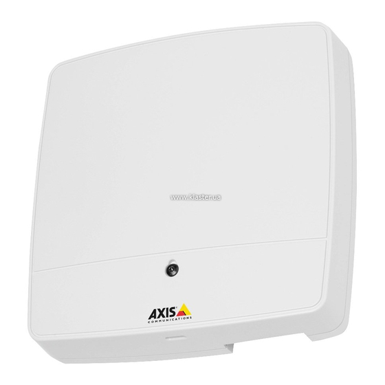
    AXIS A1001 Network Door Controller • Gedruckte Dokumente AXIS A1001 Installationsanleitung – Kurzanleitung Zusätzliche Etiketten mit der Seriennummer (2x) AVHS-Authentifizierungsschlüssel Empfohlene Werkzeuge • Bohrmaschine (für Wand- oder Deckenmontage) • Schraubendreher (für Wand- oder Deckenmontage) • Schlitzschraubendreher (zum Öffnen der Abdeckung) •...
  • Seite 93 AXIS A1001 Network Door Controller Vorder- und Rückseite: Abdeckung Schraube für Abdeckung Schlitz zum Entfernen der Abdeckung Grundplatte DIN-Halterung – obere Manipulationsalarmschalter – Rückseite DIN-Halterung – untere Bestellnummer (P/N) und Seriennummer (S/N)
  • Seite 94 AXIS A1001 Network Door Controller E/A-Schnittstelle: Leser-Daten-Anschluss (READER DATA 1) 10 Leser-Daten-Anschluss (READER DATA 2) Leser-E/A-Anschluss (READER I/O 1) Leser-E/A-Anschluss (READER I/O 2) Türanschluss (DOOR IN 1) Türanschluss (DOOR IN 2) Zusatzanschluss (AUX) Audioanschluss (AUDIO) (nicht verwendet) Externe Stromanschlüsse: Netzanschluss (DC IN) 12 Netzwerkanschluss (PoE) Stromausgänge:...
  • Seite 95 AXIS A1001 Network Door Controller LED-Anzeigen, Tasten und andere Hardware: LED-Betriebsanzeige LED-Statusanzeige LED-Netzwerkanzeige LED-Anzeige für Leser 2 (nicht verwendet) LED-Anzeige für Leser 1 (nicht verwendet) Stiftleiste für Manipulationsalarm – Vorderseite (TF) Stiftleiste für Manipulationsalarm – Rückseite (TB) LED-Anzeige für Schloss LED-Anzeige für Schloss...
  • Seite 96: Anschlüsse Und Tasten

    AXIS A1001 Network Door Controller LEDs Farbe Bedeutung Netzwerk Grün Leuchtet bei Verbindung mit einem 100 MBit/s-Netzwerk. Blinkt bei Netzwerkaktivität. Gelb Leuchtet bei Verbindung mit einem 10 MBit/s-Netzwerk. Blinkt bei Netzwerkaktivität. Leuchtet Keine Netzwerkverbindung vorhanden. nicht Leuchtet bei Normalbetrieb grün.
  • Seite 97 AXIS A1001 Network Door Controller • Digitaleingang – z. B. zum Anschließen eines Leser-Manipulationsalarms. • Digitalausgang – z. B. zum Anschließen von Leser-Signaltongebern und Leser-LEDs. Technische Daten finden Sie auf Seite 101. Türanschlüsse Zwei 4-polige Anschlussblöcke zum Anschließen von Türüberwachungsgeräten und REX-Geräten (Request to Exit).
  • Seite 98: Technische Daten

    Die Steuertaste hat folgende Funktionen: • Zurücksetzen des Produkts auf die Werkseinstellungen. Siehe Seite 125. • Verbinden mit einem AXIS Video Hosting System-Service oder einem AXIS Internet Dynamic DNS-Service. Weitere Informationen zu diesen Diensten finden Sie in der Bedienungsanleitung. Technische Daten Betriebsbedingungen Das Axis Produkt ist für die Verwendung in Innenräumen ausgelegt.
  • Seite 99 10 bis 30 V DC 14 W Die Spannung an den Stromausgängen des Axis Produkts beträgt 12 V DC (außer am Zusatzanschluss mit einer Spannung von 3,3 V DC). Wenn das angeschlossene Gerät beispielsweise über eine Ampere-Zertifizierung von 0,3 A verfügt, kann die Stromstärke mit folgender Konvertierung in Watt (W) umgerechnet werden: Leistung (W) = Spannung (V) x Stromstärke (I)
  • Seite 100: Leistungsebenen Für Die Zutrittskontrolle

    AXIS A1001 Network Door Controller Leistungsebenen für die Zutrittskontrolle Dieser Abschnitt enthält Informationen über die Leistungsebenen, die für die UL 294-Konformität erforderlich sind. Funktion Ebene Zerstörungstest Leitungsabsicherung Härtetest Notstromversorgung Aderquerschnitt HINWEIS HINWEIS HINWEIS Jede Ader muss einen Leiterquerschnitt aufweisen, der einem Leiterquerschnittsbereich nach AWG 28–16 (CSA) oder AWG 22–14 (cUL/UL) entspricht.
  • Seite 101 AXIS A1001 Network Door Controller Leser-Daten-Anschluss 6-poliger Anschlussblock für die Kommunikation mit dem Leser (unterstützt RS485- und Wiegand-Protokoll). Die RS485-Ports unterstützen: • Zweiadrig RS485 Halbduplex • Vieradrig RS485 Vollduplex Die Wiegand-Ports unterstützen: • Zweiadrig Wiegand Funktion Kontakt Hinweise RS485 RS485 für Vollduplex RS485 für Halbduplex...
  • Seite 102 AXIS A1001 Network Door Controller Funktion Kontakt Hinweise Technische Daten 0 V DC 0 V DC (-) Gleichstro- Zur Stromversorgung von 12 V DC mausgang Zusatzgeräten. Max. Stromstärke = 300 mA Hinweis: Dieser Kontakt kann nur für den Stromausgang verwendet werden.
  • Seite 103 AXIS A1001 Network Door Controller Funktion Kontakt Hinweise Technische Daten 1, 3 0 V DC 0 V DC (-) 2, 4 Eingang Zur Kommunikation der 0 bis max 40 V DC Türüberwachung. Digitaleingang – Zum Aktivieren mit Kontakt 1 bzw. 3 verbinden; zum Deaktivieren nicht anschließen.
  • Seite 104 AXIS A1001 Network Door Controller Wichtig Die empfohlene maximale Kabellänge beträgt 30 m. Wichtig Bei den Ausgangsstromkreisen in diesem Abschnitt handelt es sich um Geräte der Klasse 2 mit begrenzter Leistung. Stromanschluss 2-poliger Anschlussblock für die Gleichstromversorgung. Verwenden Sie eine mit den Anforderungen für Schutzkleinspannung (SELV) kompatible Stromquelle mit begrenzter Leistung (LPS), entweder mit einer Nennausgangsleistung von ≤100 W oder einem dauerhaft auf...
  • Seite 105 AXIS A1001 Network Door Controller Funktion Kontakt Hinweise Technische Daten 1, 3 0 V DC 0 V DC (-) 2, 4 0 V DC, frei Zur Steuerung von bis zu zwei 12 V DC oder 12 V DC 12-V-Schlössern. Verwenden Sie das Max.
  • Seite 106 AXIS A1001 Network Door Controller Manipulationsalarm-Stiftleiste Zwei 2-polige Leisten zur Überbrückung des: • Hinteren Manipulationsalarms (TB) • Vorderen Manipulationsalarms (TF) Funktion Kontakt Hinweise Hinterer 1–2 Setzen Sie die Drahtbrücken zwischen TB 1, TB 2 bzw. Manipulationsalarm TF 1, TF 2, um den vorderen bzw. hinteren Manipulationsalarm zu überbrücken.
  • Seite 107 AXIS A1001 Network Door Controller Zusatzanschluss 0 V (-) DC Gleichstromausgang: 3,3 V, max. 100 mA E/A als Eingang konfiguriert E/A als Ausgang konfiguriert Überwachte Eingänge Um überwachte Eingänge zu verwenden, die Abschlusswiderstände wie im Schaltbild unten dargestellt anschließen. Eingang...
  • Seite 108: Die Hardware Installieren

    Tür-Controller oder ein System von Tür-Controllern installiert wurde. Das Axis Produkt sollte an einer Wand (empfohlen) oder einer Decke mit oder ohne Anschlussdose installiert werden. Die Installation auf einer DIN-Schiene ist ebenfalls möglich.
  • Seite 109: Wand- Und Deckenmontage

    AXIS A1001 Network Door Controller Wand- und Deckenmontage HINWEIS HINWEIS HINWEIS Wenn der Tür-Controller an einer Wand installiert wird, muss die Aussparung für die Kabel nach unten zeigen. 1. Bei Verwendung einer Anschlussdose muss diese vor der Installation des Netzwerk-Tür-Controllers angebracht werden. UL-Konformität muss mit einer UL-gelisteten Anschlussdose gewährleistet werden.
  • Seite 110: Montage An Einer Din-Schiene

    AXIS A1001 Network Door Controller Grundplatte Bohrung (4x) 6. Schließen Sie die Kabel an. Siehe Seite 111. Montage an einer DIN-Schiene 1. Installieren Sie bei Bedarf eine DIN-Schiene (nicht enthalten). 2. Lösen Sie ggf. die Schraube für die Abdeckung, setzen Sie einen Schlitzschraubendreher in den Schlitz zum Entfernen der Abdeckung ein und entfernen Sie die Abdeckung.
  • Seite 111: Grundplatte

    Abdeckung nicht schließen. 8. Schließen Sie die Kabel an. Siehe Seite 111. Anschließen der Kabel VORSICHT Trennen Sie das Gerät vom Stromnetz, bevor Sie Kabel an das Axis Produkt anschließen. Stellen Sie niemals Verbindungen her, während das Produkt mit Strom versorgt wird.
  • Seite 112 AXIS A1001 Network Door Controller HINWEIS HINWEIS HINWEIS • Das Produkt muss mit einem abgeschirmten Netzwerkkabel (STP) angeschlossen werden. Alle Kabel, die das Produkt mit dem Netzwerkswitch verbinden, müssen hierfür ausgelegt sein. Stellen Sie sicher, dass die Netzwerkgeräte gemäß den Anweisungen des Herstellers installiert wurden.
  • Seite 113 AXIS A1001 Network Door Controller Kabelbinder Netzwerkkabel 3. Manteln Sie die Kabel und Drähte je nach Bedarf mit einem Crimpzange ab. 4. Verbinden Sie die Drähte zwischen dem Tür-Controller und den Schlössern, Türen sowie anderen Geräten. Weitere Informationen zu Anschlüssen und deren Spezifikationen finden Sie auf Seite 96 und Seite 100.
  • Seite 114 AXIS A1001 Network Door Controller Beispiel für Verkabelung 6-poliger Anschlussstecker Netzwerkkabel Kabelbinder (4x) Netzwerkanschluss Beachten • Verwenden Sie für Geräte, die auf den Hardware-Konfigurationsseiten des Produkts konfiguriert wurden, das Pin Chart als Leitfaden zum Verbinden der Kontakte. Weitere Informationen zu Hardwarekonfiguration und Pin Chart finden Sie unter Konfigurieren der Hardware auf Seite 122.
  • Seite 115 AXIS A1001 Network Door Controller kompatible Stromquelle mit begrenzter Leistung (LPS). Für weitere Informationen siehe Stromanschluss auf Seite 104 Beispiel für Verkabelung Netzwerkanschluss Netzwerkkabel 9. Vergewissern Sie sich, dass die LEDs die richtigen Zustände anzeigen. Siehe LEDs auf Seite 96.
  • Seite 116: Zugriff Auf Das Produkt

    AXIS A1001 Network Door Controller Abdeckung Schraube für Abdeckung (T10) Zugriff auf das Produkt Das Produkt ist mit den meisten Standard-Betriebssystemen und Browsern kompatibel. Empfohlen werden die Browser Internet Explorer für Windows, Safari für Macintosh und Firefox für andere Betriebssysteme.
  • Seite 117: Über Das Internet Auf Das Produkt Zugreifen

    AXIS A1001 Network Door Controller 2. Die IP-Adresse oder den Hostnamen des Axis-Produkts in die Adresszeile des Browsers eingeben. Bei unbekannter IP-Adresse das Produkt mithilfe der AXIS IP Utility im Netzwerk ermitteln. Weitere Informationen zum Ermitteln und Zuweisen von IP-Adressen finden Sie unter Zuweisen einer IP-Adresse.
  • Seite 118: Axis Camera Management - Umfangreiche Installationen

    Die Anwendung kann außerdem zur manuellen Zuweisung einer statischen IP-Adresse verwendet werden. Beachten Sie, dass sich das Axis-Produkt und der Computer, auf dem AXIS IP Utility ausgeführt wird, im gleichen Netzwerksegment (d. h. physischen Subnetz) befinden müssen. Automatische Erkennung 1.
  • Seite 119 AXIS A1001 Network Door Controller Automatische Erkennung 1. Stellen Sie sicher, dass das Axis Produkt an das Netzwerk angeschlossen ist und eingeschaltet wurde. 2. Starten Sie AXIS Camera Management. 3. Stellen Sie eine Verbindung mit einem Server her. Um eine Verbindung mit einem Server im Netzwerk herzustellen, wählen Sie Remote-Server aus.
  • Seite 120: Weitere Betriebssysteme Und Methoden

    Navigieren Sie zum Bonjour-Lesezeichen Ihres Browsers (z. B. Safari) und klicken Sie auf den Link, um die Weboberfläche aufzurufen. • AXIS Dynamic DNS Service (alle Betriebssysteme). Ein kostenloser Service von Axis, mit dem Sie Ihr Axis Netzwerkprodukt schnell und einfach installieren können. Erfordert eine Internetverbindung ohne HTTP-Proxyserver. Weitere Informationen hierzu finden Sie unter www.axiscam.net.
  • Seite 121: Das Root-Kennwort Festlegen

    AXIS A1001 Network Door Controller Windows-Beispiel (Dazu müssen Sie die Eingabeaufforderung möglicherweise als Administrator ausführen.) arp -s 192.168.0.125 00-40-8c-18-10-00 ping -l 408 -t 192.168.0.125 4. Das Produkt neu starten. Dazu die Stromversorgung der Netzwerkverbindung (PoE) unterbrechen und wiederherstellen. 5. Die Eingabeaufforderung schließen, wenn das Produkt mit Antwort von 192.168.0.125:...
  • Seite 122: Konfigurieren Der Hardware

    (Hardwarekonfiguration) konfigurieren. Türen, Etagen und Schlösser sowie andere Geräte können vor Abschluss der Hardwarekonfiguration an das Axis-Produkt angeschlossen werden. Das Anschließen von Geräten ist jedoch einfacher, wenn Sie zuerst die Hardwarekonfiguration abschließen, da Ihnen somit das Pin Chart zur Verfügung steht.
  • Seite 123: Installieren Der Hardware

    1. Lösen Sie ggf. die Schraube für die Abdeckung, setzen Sie einen Schlitzschraubendreher in den Schlitz zum Entfernen der Abdeckung ein und entfernen Sie die Abdeckung. 2. Verbinden Sie das Axis Produkt mit dem Netzwerk und warten Sie, bis die Netzwerkverbindung hergestellt und das Produkt gestartet wurde. Wenn das Produkt nicht per Power over Ethernet versorgt wird und stattdessen Ethernet sowie eine externe Stromquelle verwendet werden, muss das Produkt außerdem an eine mit den...
  • Seite 124: Eine Neue Hardwarekonfiguration Mit Elevator Control (Axis A9188) Erstellen

    > Add > User setup (Benutzereinstellungen > Weitere Gerätekonfigurationen > Grundeinstellungen > Benutzer > Hinzufügen> Benutzer einrichten) aufrufen. Beachten Pro Network Door Controller A1001 lassen sich maximal zwei Netzwerk-E/A-Relaismodule AXIS 9188 konfigurieren. 1. Unter A1001 Setup > Hardware Configuration (Setup > Hardwarekonfiguration) aufrufen und Neue Hardwarekonfiguration starten aufrufen.
  • Seite 125: Voraussetzungen Für Smartintego

    AXIS A1001 Network Door Controller 6. Optional auch imID-Feld unter Türpositionssensor: Die aus sechs Zeichen bestehende Adresse des Geräts eingeben, das hinzugefügt werden soll. Die Geräteadresse befindet sich auf dem Produktaufkleber. 7. Klicken Sie auf Add (Hinzufügen). Voraussetzungen für SmartIntego Bevor SmartIntego konfiguriert werden kann, müssen folgende Voraussetzungen erfüllt sein:...
  • Seite 126 5. Mithilfe der Software-Tools für Installation und Verwaltung können Sie eine IP-Adresse zuweisen, das Kennwort festlegen und auf das Produkt zugreifen. Wartungsanweisungen Für einen reibungslosen Betrieb des Zugangskontrollsystems empfiehlt Axis eine regelmäßige Wartung des Systems, einschließlich Tür-Controller und angeschlossener Geräte. Die Wartung sollte mindestens einmal pro Jahr erfolgen. Die empfohlene Wartungsprozedur umfasst unter anderem die folgenden Schritte: •...
  • Seite 127: Weitere Informationen

    Die aktuelle Version dieses Dokuments finden Sie auf axis.com • Das Benutzerhandbuch steht auf axis.com zur Verfügung. • Unter axis.com/support finden Sie die aktuellen Firmwareversionen für Ihre Produkte. • Nützliches Onlinetraining und Webinare finden Sie unter axis.com/academy. Gewährleistungsinformationen Informationen zur Gewährleistung für Axis-Produkte und andere in diesem Zusammenhang...
  • Seite 129: Informazioni Di Sicurezza

    AXIS A1001 Network Door Controller Informazioni di sicurezza Livelli di pericolo PERICOLO Indica una situazione pericolosa che, se non evitata, provoca morte o lesioni gravi. AVVERTENZA Indica una situazione pericolosa che, se non evitata, potrebbe provocare la morte o lesioni gravi.
  • Seite 130 • Durante il trasporto del dispositivo Axis, utilizzare l'imballaggio originale o equivalente per evitare danni al dispositivo. Batteria Il dispositivo Axis utilizza una batteria al litio da 3,0 V CR2032 come alimentazione per il suo real-time clock (RTC) interno. In condizioni normali questa batteria avrà una durata minima di cinque anni.
  • Seite 131 • Rischio di esplosione se la batteria viene sostituita in modo errato. • Sostituire solo con una batteria identica o una batteria consigliata da Axis. • Smaltire le batterie usate in base alle normative locali o alle istruzioni del produttore...
  • Seite 133: Procedura Di Installazione

    AXIS A1001 nella rete in uso. • Per una guida di riferimento rapido, vedere il documento AXIS A1001 Guida all'installazione - Riferimento rapido incluso nel contenuto della confezione. La guida di riferimento rapido è disponibile anche all'indirizzo www.axis.com •...
  • Seite 134: Panoramica Dell'hardware

    AXIS A1001 Network Door Controller • Materiali cartaceo Guida all'installazione di AXIS A1001 - Riferimento rapido Etichetta aggiuntiva con numero di serie (2x) Chiave di autenticazione AVHS Strumenti raccomandati • Trapano: in caso di montaggio a parete o a soffitto •...
  • Seite 135 AXIS A1001 Network Door Controller Vista anteriore e posteriore: Coperchio Vite del coperchio Slot di rimozione coperchio Base Clip DIN superiore Interruttore allarme anti-manomissione - retro Clip DIN inferiore Codice dispositivo (N/P) e numero di serie (N/S)
  • Seite 136 AXIS A1001 Network Door Controller Interfaccia I/O: Connettore dati lettore (READER DATA 1) 10 Connettore dati lettore (READER DATA 2) Connettore I/O lettore (READER I/O 1) Connettore I/O lettore (READER I/O 2) Connettore porta (DOOR IN 1) Connettore porta (DOOR IN 2)
  • Seite 137 AXIS A1001 Network Door Controller Indicatori LED, pulsanti e altro hardware: Indicatore LED di alimentazione Indicatore LED di stato Indicatore LED di rete Indicatore LED 2 del lettore (non utilizzato) Indicatore LED 1 del lettore (non utilizzato) Collettore pin allarmi anti-manomissione - fronte (TF)
  • Seite 138: Led Indicators

    AXIS A1001 Network Door Controller LED Indicators Color Indication Network Green Steady for connection to a 100 MBit/s network. Flashes for network activity. Amber Steady for connection to a 10 MBit/s network. Flashes for network activity. Unlit No network connection.
  • Seite 139 AXIS A1001 Network Door Controller Per le specifiche, consultare pagina 143. Connettori porta Due morsettiere a 4 pin per il collegamento di dispositivi di monitoraggio porta e dispositivi REX (Request to Exit). Per le specifiche, consultare pagina 144. Connettore ausiliario Morsettiera I/O a 4 pin configurabile.
  • Seite 140: Dati Tecnici

    14 W Conversione uscita alimentazione (da W ad A) Se l'alimentatore che si collega al dispositivo Axis ha solo una classificazione ampere (A), il seguente metodo può essere utilizzato per la conversione in watt (W). Il carico di uscita massima totale del dispositivo Axis dipende dalla sorgente di alimentazione:...
  • Seite 141 10–30 V CC 14 W La tensione in uscita del dispositivo Axis è di 12 V CC (tranne per il connettore ausiliario che ha una tensione di 3,3 V CC). Se l'alimentatore ha una classificazione massima di ampere di ad esempio 0,3...
  • Seite 142 AXIS A1001 Network Door Controller Sicurezza linea Durata IV - Video Intelligente Alimentazione standby Area di cablaggio A A A VVISO VVISO VVISO Per ogni cavo l'area della sezione del conduttore deve corrispondente all'intervallo dei calibri dei conduttori 28-16 AWG (CSA) o 22-14 AWG (cUL/UL). Selezionare i cavi nel rispetto delle normative locali.
  • Seite 143 AXIS A1001 Network Door Controller Funzione Nota RS485 Per RS485 full duplex Per RS485 half duplex RS485 Per RS485 full duplex Per RS485 half duplex Wiegand Per Wiegand D0 (Dati 0) D1 (Dati 1) Importante Le porte RS485 hanno una velocità di trasmissione fissa di 9600 Bit/s.
  • Seite 144: Connettore Porta (Door In 1)

    AXIS A1001 Network Door Controller 3–6 Configurabile Ingresso digitale: collegare al pin 1 per Da 0 a max 40 V CC (ingresso o attivare oppure lasciare isolato uscita) (scollegato) per disattivare. Uscita digitale: collegare al pin 1 per Da 0 a max 40 V CC,...
  • Seite 145: Connettore Ausiliario (Aux)

    AXIS A1001 Network Door Controller Connettore ausiliario Morsettiera I/O a 4 pin configurabile per: • Alimentazione ausiliaria (uscita CC) • Ingresso digitale • Uscita digitale • 0 V CC (-) Per un esempio di schema delle connessioni, consultare Schemi delle connessioni alla pagina 148.
  • Seite 146: Connettore Di Rete (Poe)

    AXIS A1001 Network Door Controller Funzione Nota Specifiche 0 V CC 0 V CC (-) Per l'alimentazione del controller Ingresso CC 10-30 V CC, max 26 W quando non si usa Power over Ethernet. Carico massimo in Nota: questo pin può essere usato solo uscita = 14 W come ingresso alimentazione.
  • Seite 147: Connettore Di Alimentazione E Relè (Pwr, Relay)

    AXIS A1001 Network Door Controller Connettore di alimentazione e relè Morsettiera a 6 pin con relè integrato per: • Dispositivi esterni • Alimentazione ausiliaria (uscita CC) • 0 V CC (-) Collegare blocchi e carichi ai pin in base allo schema dei pin hardware generato tramite la configurazione dell'hardware.
  • Seite 148 AXIS A1001 Network Door Controller Nota Gli allarmi anti-manomissione anteriore e posteriore sono collegati per impostazione predefinita. È possibile configurare l'attivazione di apertura della struttura in modo che esegua un'azione se il door controller viene aperto o rimosso dalla parete o dal soffitto. Per informazioni sulla configurazione di allarmi ed eventi, consultare il Manuale Utente.
  • Seite 149: Installazione Dell'hardware

    Il dispositivo Axis deve essere installato nell'area protetta. Il dispositivo Axis, se è installato come un singolo dispositivo di controllo porta o in un sistema di dispositivi di controllo porta, non limita o indebolisce la destinazione d'uso dei dispositivi ad esso collegati.
  • Seite 150 La quantità di blocchi wireless configurati per ogni gateway dipende dal produttore. Nota • I blocchi wireless non sono venduti e distribuiti da Axis Communications. Per il supporto e la formazione relativa ai sistemi wireless, rivolgersi al partner dei produttori.
  • Seite 151: Montaggio Su Guida Din

    AXIS A1001 Network Door Controller Base Foro per vite (4) 6. Collegare i cavi. Consultare pagina 152. Montaggio su guida DIN 1. Se necessario, installare una guida DIN (non inclusa). 2. Se necessario, rimuovere la vite del coperchio, inserire un cacciavite scanalato nello slot di rimozione del coperchio e rimuovere il coperchio.
  • Seite 152: Collegamento Dei Cavi

    (0,1 pollici). La curvatura della base impedirebbe la chiusura del coperchio. 8. Collegare i cavi. Consultare pagina 152. Collegamento dei cavi ATTENZIONE Scollegare l'alimentazione prima di collegare qualsiasi cavo al prodotto Axis. Non effettuare mai collegamenti mentre il prodotto viene alimentato.
  • Seite 153 AXIS A1001 Network Door Controller A A A VVISO VVISO VVISO • Il dispositivo deve essere collegato con un cavo di rete schermato (STP). Tutti i cavi che collegano il dispositivo alla rete sono destinati al loro uso specifico. Verificare che i dispositivi di rete siano installati secondo le istruzioni del produttore.
  • Seite 154 AXIS A1001 Network Door Controller 3. Spellare i cavi come richiesto utilizzando una crimpatrice. 4. Collegare i cavi tra il door controller e le serrature, le porte e gli altri dispositivi. Per ulteriori informazioni sui connettori e le relative specifiche, consultare pagina 138 e pagina 142.
  • Seite 155 AXIS A1001 Network Door Controller Per ulteriori informazioni sulla configurazione dell'hardware e lo schema dei pin hardware, consultare Configurazione dell'hardware alla pagina 162. • Per informazioni sul collegamento degli altri cavi, quali i cavi di alimentazione di serrature, lettori e altri dispositivi, consultare le istruzioni dei produttori.
  • Seite 156 AXIS A1001 Network Door Controller 10. Fissare il coperchio alla base e serrare la vite del coperchio. Coperchio Vite del coperchio (T10) Accedere al dispositivo Il dispositivo può essere utilizzato con la maggior parte dei sistemi operativi e dei browser. I browser consigliati sono Internet Explorer con Windows, Safari con Macintosh e Firefox con gli altri sistemi operativi.
  • Seite 157 Per ulteriori informazioni sulla funzione di attraversamento NAT per IPv4, consultare il Manuale Utente del dispositivo. Per le note tecniche su questo e altri argomenti, visitare il sito Web dell'assistenza Axis all’indirizzo www.axis.com/support Vedere anche l'AXIS Internet Dynamic DNS Service all'indirizzo www.axiscam.net...
  • Seite 158 AXIS A1001 Network Door Controller Metodi consigliati in Windows® AXIS IP Utility e AXIS Camera Management sono i metodi consigliati per trovare i dispositivi Axis in rete e assegnare loro un indirizzo IP in Windows®. Queste applicazioni sono entrambe gratuite e possono essere scaricate dal sito Web all'indirizzo: www.axis.com/techsup...
  • Seite 159 7. Per informazioni su come impostare la password, consultare pagina 161. Assegnazione di indirizzi IP su più periferiche AXIS Camera Management velocizza il processo di assegnazione degli indirizzi IP di più periferiche, suggerendo gli indirizzi IP in base a un intervallo specifico.
  • Seite 160 AXIS Dynamic DNS Service (tutti i sistemi operativi). Servizio gratuito fornito da Axis che consente di installare il prodotto di rete Axis in modo facile e veloce. È necessaria una connessione a Internet senza proxy HTTP. Per ulteriori informazioni, accedere alla pagina www.axiscam.net...
  • Seite 161 Application > Utilities (Applicazione > Utilità). Come impostare la password root Per accedere al dispositivo Axis, è necessario impostare la password dell’utente amministratore predefinito root. Questa operazione viene effettuata nella finestra di dialogo Configure Root Password (Configura password root), visualizzata quando si accede al dispositivo per la prima volta.
  • Seite 162: Configurazione Dell'hardware

    Prima di installare il dispositivo, configurare l'hardware nelle pagine Hardware Configuration (Configurazione hardware). Porte, piani, serrature e altri dispositivi possono essere collegati al dispositivo Axis prima di completare la configurazione dell'hardware. Tuttavia, tale collegamento risulta più semplice se viene effettuato dopo aver completato la configurazione dell'hardware. Ciò è dovuto al fatto che al termine della configurazione è...
  • Seite 163 AXIS A1001 Network Door Controller 2. Collegare il dispositivo Axis alla rete e attendere l'attivazione del collegamento di rete e l'accensione del dispositivo. Se il dispositivo non riceve alimentazione tramite Power over Ethernet ma utilizza invece Ethernet e una sorgente di alimentazione esterna, collegare il dispositivo anche a una sorgente di alimentazione limitata (LPS) compatibile con una bassissima tensione di sicurezza (SELV).
  • Seite 164 AXIS A1001 Network Door Controller Nota È possibile configurare max 2 moduli relè I/O di rete AXIS 9188 con ogni controller della porta di rete A1001 1. In A1001, andare a Setup > Hardware Configuration (Configurazione > Configurazione hardware) e fare clic su Start new hardware configuration (Avvia una nuova configurazione hardware).
  • Seite 165: Modalità Di Ripristino Dei Valori Predefiniti Di Fabbrica

    AXIS A1001 Network Door Controller Prerequisiti SmartIntego I seguenti prerequisiti devono essere soddisfatti prima di procedere con la configurazione SmartIntego: • Deve essere creato un file csv. Il file csv contiene informazioni sul GatewayNode e le porte utilizzate nella soluzione SmartIntego. Il file viene creato in un software indipendente fornito da un partner SimonsVoss.
  • Seite 166: Istruzioni Di Manutenzione

    IP, impostare la password e accedere al dispositivo. Istruzioni di manutenzione Per tenere il sistema di controllo degli accessi in buono stato di funzionamento, Axis ne consiglia la regolare manutenzione, che deve includere door controller e dispositivi collegati. Effettuare la manutenzione almeno una volta all'anno. Le procedure di manutenzione consigliate, includono, a titolo esemplificativo, i passaggi seguenti: •...
  • Seite 167: Informazioni Sulla Garanzia

    AXIS A1001 Network Door Controller • Per servizi di formazione utili e webinar, visita il sito axis.com/academy Informazioni sulla garanzia Per informazioni sulla garanzia del dispositivo Axis e informazioni ad esso relative, consultare la pagina axis.com/warranty/...
  • Seite 169: Información De Seguridad

    AXIS A1001 Network Door Controller Información de seguridad Niveles de peligro PELIGRO Indica una situación peligrosa que, si no se evita, provocará lesiones graves o la muerte. ADVERTENCIA Indica una situación peligrosa que, si no se evita, puede provocar lesiones graves o la muerte.
  • Seite 170: Instrucciones De Seguridad

    Batería Este producto de Axis utiliza una batería de litio CR2032 de 3,0 V como fuente de alimentación del reloj interno en tiempo real. En condiciones normales, esta batería durará un mínimo de cinco años.
  • Seite 171 La batería no debe sustituirse a menos que sea necesario; no obstante, si precisa hacerlo, póngase en contacto con el servicio de asistencia técnica de Axis en axis.com/support para solicitar ayuda. Las pilas de botón de litio de 3,0 V contienen 1,2-dimetoxietano; éter dimetílico de etilenglicol (EGDME), n.º...
  • Seite 173: Contenido Del Paquete

    AXIS A1001 en su red. • Si desea consultar una guía de referencia rápida, vea la Guía de instalación – Referencia rápida impresa de AXIS A1001 incluida en el contenido del paquete. Esta guía de referencia rápida también está disponible en www.axis.com •...
  • Seite 174: Herramientas Recomendadas

    AXIS A1001 Network Door Controller • Materiales impresos Guía de instalación del AXIS A1001 - Referencia rápida Etiquetas adicionales con el número de serie (x2) Clave de autenticación AVHS Herramientas recomendadas • Taladro: para realizar el montaje en pared o techo •...
  • Seite 175 AXIS A1001 Network Door Controller Parte delantera y trasera: Cubierta Tornillo de la cubierta Ranura de desmontaje de la cubierta Base Clip DIN (superior) Interruptor de alarma antimanipulación (posterior) Clip DIN (inferior) Número de pieza (N/P) y número de serie (N/S)
  • Seite 176 AXIS A1001 Network Door Controller Interfaz de E/S: Conector de datos del lector (READER DATA 1) 10 Conector de datos del lector (READER DATA 2) Conector de E/S del lector (READER I/O 1) Conector de E/S del lector (READER I/O 2)
  • Seite 177 AXIS A1001 Network Door Controller Indicadores LED, botones y otro hardware: Indicador LED de alimentación Indicador LED de estado Indicador LED de red Indicador LED 2 del lector (no se usa) Indicador LED 1 del lector (no se usa) Cabezal con pines de la alarma antimanipulación (delantero) (TF) Cabezal con pines de la alarma antimanipulación (trasero) (TB)
  • Seite 178 AXIS A1001 Network Door Controller LED Indicators Color Indication Network Green Steady for connection to a 100 MBit/s network. Flashes for network activity. Amber Steady for connection to a 10 MBit/s network. Flashes for network activity. Unlit No network connection.
  • Seite 179 AXIS A1001 Network Door Controller Para conocer las especificaciones, consulte página 183. Conectores de puerta Dos bloques terminales de 4 pines para conectar dispositivos de monitor de puerta y solicitud para dispositivos de salida (REX). Para conocer las especificaciones, consulte página 184.
  • Seite 180: Condiciones De Funcionamiento

    Restablecer el producto a la configuración predeterminada de fábrica. Consulte página 206. • Conectarse a un servicio AXIS Video Hosting System o al Servicio de DNS dinámico de Internet de AXIS. Para obtener más información sobre estos servicios, consulte el Manual del usuario.
  • Seite 181 14 W La tensión en las salidas de alimentación del producto de Axis es de 12 V CC (excepto en el conector auxiliar, donde la tensión es de 3,3 V CC) Si el dispositivo que va a conectar tiene un amperaje máximo de, por ejemplo, 0,3 A, la siguiente fórmula le permite convertir la alimentación a...
  • Seite 182 AXIS A1001 Network Door Controller Niveles de rendimiento para control de acceso Esta sección contiene información sobre el nivel de rendimiento necesario para lograr la conformidad con UL 294. Nivel Función Prueba de ataques destructivos Seguridad de línea Resistencia Alimentación en reposo Área de los cables...
  • Seite 183 AXIS A1001 Network Door Controller Conector de datos del lector Bloque de terminales de 6 pines compatibles con los protocolos RS485 y Wiegand para la comunicación con el lector. Los puertos RS485 admiten: • Semidúplex RS485 de dos cables • Dúplex completo RS485 de cuatro cables Los puertos Wiegand admiten: •...
  • Seite 184: Conector De Puerta (Door In 1)

    AXIS A1001 Network Door Controller Notas Función Especificaciones 0 V CC 0 V CC (-) Salida de CC Para alimentar el equipo auxiliar. 12 V CC Nota: Este pin solo se puede utilizar Carga máx. = 300 mA como salida.
  • Seite 185: Conector Auxiliar (Aux)

    AXIS A1001 Network Door Controller Importante La longitud de cable máxima recomendada es 30 m. Conector auxiliar Bloque de terminales de E/S configurable de 4 pines para: • Alimentación auxiliar (salida de CC) • Entrada digital • Salida digital • 0 V CC (-) Para ver un ejemplo del diagrama de conexiones, consulte Diagramas de conexión en la página 188.
  • Seite 186: Conector De Red (Poe)

    AXIS A1001 Network Door Controller Notas Función Especificaciones 0 V CC 0 V CC (-) Entrada de CC Para alimentar el controlador cuando 10–30 V CC, máx. 26 W no se use la alimentación a través de Carga máxima en las Ethernet.
  • Seite 187: Conector De Alimentación Y Relé (Pwr, Relay)

    AXIS A1001 Network Door Controller Conector de alimentación y relé Bloque de terminales de 6 pines con relé integrado para: • Dispositivos externos • Alimentación auxiliar (salida de CC) • 0 V CC (-) Conecte las cerraduras y las cargas a los pines según el gráfico de pines del hardware generado mediante la configuración de hardware.
  • Seite 188: Diagramas De Conexión

    AXIS A1001 Network Door Controller Nota Las alarmas antimanipulación delantera y la trasera están conectadas de forma predeterminada. El activador de carcasa abierta se puede configurar para que realice una acción si el controlador de puerta está abierto o si se ha retirado de la pared o el techo.
  • Seite 189: Instalación Del Hardware

    El producto de Axis debe instalarse en una pared (opción recomendada) o en el techo (con o sin caja de conexiones). También se puede instalar en un carril DIN.
  • Seite 190 AXIS A1001 Network Door Controller grupo). Cada producto de Axis puede conectarse hasta a dos puertas con cable o a una puerta con cable junto con una puerta de enlace inalámbrica. La cantidad de cierres inalámbricos configurados para cada puerta de salida depende del fabricante.
  • Seite 191 AXIS A1001 Network Door Controller Base Orificio para tornillo (4x) 6. Conecte los cables. Consulte página 192. Montaje en raíl DIN 1. Si procede, se puede instalar un raíl DIN (no incluido). 2. Si procede, quite el tornillo de la cubierta, inserte un destornillador plano en la ranura de extracción de la cubierta y retire la cubierta.
  • Seite 192: Conexión De Los Cables

    2,5 mm (0,1 pulg.). Si la base se queda doblada, la cubierta no cerrará. 8. Conecte los cables. Consulte página 192. Conexión de los cables ATENCIÓN Desconecte la alimentación antes de conectar cualquier cable al producto de Axis. Nunca efectúe conexiones mientras el dispositivo esté conectado a la alimentación.
  • Seite 193 AXIS A1001 Network Door Controller A A A VISO VISO VISO • El producto se conectará mediante un cable de red blindado (STP). Todos los cables que conecten el producto a la red deberán estar blindados para su uso específico. Asegúrese de que los dispositivos de red estén instalados de conformidad con las instrucciones del...
  • Seite 194 AXIS A1001 Network Door Controller Abrazadera de cable Cable de red 3. Pele los cables según se requiera con una herramienta de crimpar. 4. Conecte los cables entre el controlador de puerta y las cerraduras, las puertas y otros dispositivos. Para obtener más información sobre los conectores y sus especificaciones, consulte página 178 y página 182.
  • Seite 195 AXIS A1001 Network Door Controller Ejemplo de conexión de cables Conector con enchufe de 6 pines Cable de red Abrazadera de cable (4x) Conector de red Nota • Para los dispositivos que se hayan configurado mediante las páginas de configuración de hardware del producto, use el gráfico de pines del hardware como guía para saber cómo...
  • Seite 196 AXIS A1001 Network Door Controller Ejemplo de conexión de cables Conector de red Cable de red 9. Asegúrese de que los indicadores LED indiquen las condiciones correctas. Consulte LED Indicators en la página 178. 10. Fije la cubierta a la base y apriete los tornillos de la cubierta.
  • Seite 197: Acceso Al Producto

    Para establecer la contraseña de root, vea página 202. Cómo acceder al producto desde un navegador 1. Inicie un navegador web. 2. Introduzca la dirección IP o el nombre del host del producto de Axis en el campo de dirección del navegador.
  • Seite 198: Asignación De Una Dirección Ip

    Para obtener más información acerca de NAT transversal para IPv4, consulte el manual del usuario del producto. Para acceder a las notas técnicas sobre este y otros temas, consulte el sitio web de soporte de Axis, en www.axis.com/support. Consulte también la información sobre el servicio de DNS dinámico de Internet de AXIS, en www.axiscam.net .
  • Seite 199 La utilidad AXIS IP Utility localiza y muestra automáticamente los productos de Axis de su red. La aplicación puede utilizarse también para asignar manualmente direcciones IP estáticas. Tenga en cuenta que el ordenador donde esté instalada la utilidad AXIS IP Utility debe estar en el mismo segmento de red (subred física) que el producto de Axis.
  • Seite 200 7. Para obtener más información sobre cómo configurar la contraseña, consulte página 202. Asignar direcciones IP en varios dispositivos AXIS Camera Management acelera el proceso de asignación de direcciones IP en varios dispositivos indicando las direcciones IP disponibles dentro de un intervalo especificado.
  • Seite 201 AXIS A1001 Network Door Controller • UPnP™ (Windows®). Cuando está activado en un equipo, el producto de red de Axis se detecta automáticamente y se agrega a Network/My Network Places (Red/Mis sitios de red). • Bonjour (Mac OS X® 10.4 o versiones posteriores). Aplicable a todos los navegadores compatibles con Bonjour.
  • Seite 202: Configuración Del Hardware

    > Utilities (Aplicación > Utilidades). Cómo establecer la contraseña root Para acceder al producto de Axis, debe definir la contraseña para el administrador root predeterminado. Esta acción se lleva a cabo en el cuadro de diálogo Configure Root Password (Configurar contraseña de root), que se abre cuando se accede al producto por primera vez.
  • Seite 203: Conexión Del Hardware

    2. Conecte el producto de Axis a la red y espere hasta que la conexión de red se haya establecido y el producto tenga alimentación. Si el producto no cuenta con alimentación a través de Ethernet, sino que usa Ethernet y alimentación externa en su lugar, también...
  • Seite 204 > Basic setup > Users > Add > User setup (Preferencias > Configuración del dispositivo adicional> Configuración básica> Usuarios> Agregar> Configuración de usuario). Nota Se puede configurar un máximo de 2 módulos de relé y E/S de red AXIS 9188 con cada controlador de accesos en red A1001.
  • Seite 205 2. Introduzca el nombre del producto Axis. 3. Seleccione el control de ascensor que desea incluir el módulo de relé y E/S de red AXIS A9188 y haga clic en Next (Siguiente) 4. Introduzca el nombre del lector conectado.
  • Seite 206 AXIS A1001 Network Door Controller • Hay que crear un archivo csv. El archivo csv contiene información sobre el GatewayNode y las puertas que se utilizan en la solución SmartIntego. El archivo se crea en un software autónomo proporcionado por un socio de SimonsVoss.
  • Seite 207: Instrucciones De Mantenimiento

    AXIS A1001 Network Door Controller Instrucciones de mantenimiento Para mantener el sistema de control de acceso funcionando correctamente, Axis recomienda efectuarle un mantenimiento periódico, incluidos los controladores de puerta y los dispositivos conectados. Efectúe tareas de mantenimiento al menos una vez al año. El procedimiento de mantenimiento sugerido incluye, aunque sin limitarse a ellos, los siguientes pasos: •...
  • Seite 208: Información De Garantía

    AXIS A1001 Network Door Controller • Para consultar webinars y cursos en línea que pueden resultarle útiles, vaya a axis.com/academy. Información de garantía Para obtener más detalles sobre la garantía del producto Axis y la información relacionada con ella, visite axis.com/warranty.
  • Seite 210 Installation Guide Ver. M2.7 AXIS A1001 Network Door Controller Date: July 2017 © Axis Communications AB, 2013 - 2017 Part No. 1761694...