Lenze 8200 motec Montageanleitung
Vorschau ausblenden
Andere Handbücher für 8200 motec:
- Betriebsanleitung (268 Seiten) ,
- Montageanleitung (210 Seiten) ,
- Betriebsanleitung und ersatzteilkatalog (105 Seiten)

Verwandte Anleitungen für Lenze 8200 motec


Inhaltszusammenfassung für Lenze 8200 motec
- Seite 1 Show/Hide Bookmarks EDK82MV3 00403284 Montageanleitung Mounting Instructions Instructions de montage 8200 motec 0.55 kW ... 2.2 kW...
- Seite 2 - E82MV751 Manual EDB82MVU-GB - E82MV152 EDB82MVF-F - E82MV222 8200mot022/23 8200mot020/21 Der 8200 motec enthält elektrosta- The 8200 motec contains Le 8200 motec comprend des tisch gefährdete Bauelemente! electrostatically endangered composants à décharges components! électrostatiques ! Vor Arbeiten im Bereich der An- schlüsse muß...
-
Seite 3: Sicherheits- Und Anwendungshinweise Für Antriebsstromrichter
Show/Hide Bookmarks Sicherheitshinweise Antriebsregler Sicherheits- und Anwendungshinweise für Antriebsstromrichter (gemäß: Niederspannungsrichtlinie 73/23/EWG) 1. Allgemein Während des Betriebes können Antriebsstromrichter ihrer Schutzart entsprechend spannungsführende, blanke, gegebenenfalls auch bewegliche oder rotierende Teile, sowie heiße Oberflächen besitzen. Bei unzulässigem Entfernen der erforderlichen Abdeckung, bei unsachgemäßem Einsatz, bei falscher Installation oder Bedienung, besteht die Gefahr von schweren Personen- oder Sachschäden. - Seite 4 Show/Hide Bookmarks Sicherheitshinweise Drehstrommaschine Sicherheitshinweise für den Betrieb von Drehstrommaschinen (gemäß: Niederspannungsrichtlinie 73/23/EWG) 1. Allgemein Niederspannungsmaschinen haben gefährliche, spannungsführende und rotierende Teile sowie möglicherweise heiße Oberflächen. Alle Arbeiten zum Transport, Anschluß, zur Inbetriebnahme und Instandhaltung sind von qualifiziertem, verantwortlichem Fachpersonal auszuführen (prEN 50110-1/ VDE 0105; IEC 364 beachten).
- Seite 5 Show/Hide Bookmarks Safety and Operating Instructions for Controllers (in conformity with the Low-Voltage Directive 73/23/EEC) Safety Instructions controllers 1. General In operation, drive converters, depending on their degree of protection, may have live, uninsulated, and possibly also moving or rotating parts, as well as hot surfaces.
- Seite 6 Show/Hide Bookmarks Safety and Operating Instructions for three-phase AC machines (in confirmity with LOW-Voltage Directive 73/23/EEC) Safety Instructions three–phase AC machines 1. General Low-voltage machines have dangerous live and rotating parts and possibly hot surfaces. All operations serving transport, connection, commissioning and maintenance are to be carried out by skilled, responsible technical personnel (in conformity with prEN 50110-1/ VDE 0105;...
- Seite 7 Show/Hide Bookmarks Consignes de sécurité - Convertisseurs de fréquence Instructions de sécurité et d’emploi relatives aux convertisseurs d’entraînement (conformes à la directive Basse Tension 73/23/CEE) 1. Généralités Selon leur degré de protection, les convertisseurs d’entraînement peuvent comporter, pendant leur fonctionnement, des parties nues sous tension, éventuelle- ment en mouvement ou tournantes, ainsi que des surfaces chaudes.
- Seite 8 Show/Hide Bookmarks Instructions de sécurité pour l’utisilation de machines à courant triphasé (Conformes à la directive Basse Tension 73/23/CEE) Consignes de sécurité - Machines à courant triphasé 1. Généralités Les machines BT comportent des parties dangéreuses sous tension et tournantes, ainsi que, le cas échéant, des surfaces chaudes. L’ensemble des opérations relatives au transport, au raccordement, à...
- Seite 9 Show/Hide Bookmarks Technische Daten Technical Data Spécifications techniques Temperaturbereiche Temperaturbereiche Transport -25 5C0 + 70 5C Lagerung Storage Stockage -25 5C0 + 60 5C Temperature ranges Temperature ranges Betrieb Operation Service -20 5C0 + 40 5C; + 40 5C0 + 60 5C (2,5%/K) Plages de température PG-Verschraubungen PG Verschraubungen...
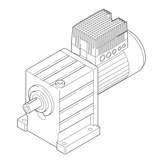
- Seite 10 Show/Hide Bookmarks motec mit Motor oder Getriebemotor motec with motor or geared motor motec avec moteur ou motoréducteur 8200mot002 EDM82MVDG 1.0 D/GB/F...
- Seite 11 Show/Hide Bookmarks Lieferumfang (Wand- / Motormontage) Packing list (wall / motor mounting) Equipement livré (montage au mur / sur le moteur) M4 x 25 8200mot003 Trägergehäuse Carrier housing Support Elektronikmodul Electronics module Module électronique Dichtung Gasket Joint Distanz- und Wandplatte Distance and wall-mounting plate Plaque de montage au mur Verschlußplatte Wandmontage...
- Seite 12 Show/Hide Bookmarks Wandmontage Wall mounting Montage au mur 8200mot004 Kabelverschraubung aus Metall für Mo- Metal cable connector for motor cable Presse-étoupe métallique pour le câble torleitung (z.B. EMV-Kabelverschrau- (e.g. EMC cable connection) moteur (presse-étoupe CEM par exem- bung) ple) EDM82MVDG 1.0 D/GB/F...
- Seite 13 Show/Hide Bookmarks Wandmontage Wall mounting Montage au mur 8200mot005 Leitungsschirm großflächig mit PE ver- Connect the cable screen with a Fixer le blindage des câbles par une surface binden surface as large as possible with PE large sur PE E82MVxxx ³ 1 mm , geschirmt E82MVxxx ³...
- Seite 14 Show/Hide Bookmarks Motoranschluß bei Wandmontage Motor connection for wall mounting Raccordement moteur pour la version “montage au mur” 8200mot006 Schutzkappe des Funktionsmoduls ent- Remove the protection cover of the Enlever le capot du module de fonction ! fernen! function module! EDM82MVDG 1.0 D/GB/F...
- Seite 15 Show/Hide Bookmarks Motormontage Motor mounting Montage sur le moteur 8200mot007 2a und 3 verwenden, falls Distanz notwen- Use 2a and 3, if a distance is necessary Utiliser 2a et 3 si écart nécessaire Fächerscheibe nach DIN 6798 Serrated lock washer to DIN 6798 Rondelle à...
- Seite 16 Show/Hide Bookmarks Motoranschluß bei Motormontage Motor connection for motor mounting Raccordement moteur pour la version “montage sur le moteur” 8200mot008 Motorschaltungsart gemäß Typenschild Motor connection to Type de couplage moteur selon plaque nameplate signalétique Schutzkappe des Funktionsmoduls entfer- Remove the protection cover Enlever le capot du module de fonction ! nen! of the function module!
- Seite 17 Show/Hide Bookmarks Netzanschluß Mains connection Raccordement réseau 0.5...0.6 Nm 1.5 mm 4.4...5.3 lbin BR2 BR1 BR0 K14 K12 K11 5.5 mm AWG 16 0,5...0,6 Nm 6 mm 4.4...5.3 lbin K14 K12 K11 AC 250 V /3A DC 60 V /1A … 200 V /0,25A BR2 BR1 BR0 3.4 Nm 30 lbin...
- Seite 18 Show/Hide Bookmarks Internes Zubehör Internal accessories Accessoires internes 8200mot010 Netzschleifklemme Mains-bus connector Bornier pour bouclage de câbles réseau Lüfter-Anschlußklemme Fan connection terminal Bornier de raccordement ventilateur Systemklemmen System terminals Bornier système bei Brückengleichrichter With bridge rectifiers Avec pont redresseur bei Einweggleichrichter With half-wave rectifiers Avec redresseur mono-alternance EDM82MVDG 1.0 D/GB/F...
- Seite 19 Show/Hide Bookmarks Abschirmung Steuerleitung Control cable shield Blindage des câbles de commande 8200mot011 Alle Steuerleitungen geschirmt verle- Screen all control cables! Blinder impérativement les câbles de gen! commande ! Alternativ zur dargestellten Befestigung As alternative for the connection shown Autre fixation possible : Utiliser un an- kann eine Kabelschelle verwendet it is also possible to use a cable clamp.
- Seite 20 Show/Hide Bookmarks Steueranschlüsse Standard–I/O Control connections standard–I/O Raccordement partie commande pour E/S standard GND1 GND2 GND1 +20V 20 28 E1 E2 E3 E4 39 A1 59 AOUT1 AIN1 DIGOUT1 1k … 10k 0 … 5 V GND1 GND2 GND1 +20V 62 7 20 28 E1 E2 E3 E4 39 A1 59 AOUT1...
- Seite 21 Show/Hide Bookmarks Steueranschlüsse Application–I/O Control connections application–I/O Raccordement partie commande pour E/S application 8200mot013 Interne Steuerspannung Internal control voltage Tension de commande interne Externe Steuerspannung External control voltage Tension de commande externe Signal AINx Jumper A Jumper B ° Pont A Pont B °...
- Seite 22 Show/Hide Bookmarks Steueranschlüsse RS485 / PROFIBUS Control connections RS485 / PROFIBUS Raccordement partie commande pour RS485 / PROFIBUS 8200mot014 Interne Steuerspannung für X3/28 Internal control voltage for X3/28 (CINH) Tension de commande interne pour (CINH) X3/28 (CINH) Externe Steuerspannung für X3/28 External control voltage for X3/28 Tension de commande externe pour (CINH)
- Seite 23 Show/Hide Bookmarks Steueranschlüsse INTERBUS Control connections INTERBUS Raccordement partie commande pour INTERBUS 8200mot015 Interne Steuerspannung für X3/28 Internal control voltage for X3/28 Tension de commande interne pour X3/28 (CINH) (CINH) (CINH) Externe Steuerspannung für X3/28 External control voltage for X3/28 Tension de commande externe pour X3/28 (CINH) (CINH)
- Seite 24 Show/Hide Bookmarks Steueranschlüsse Systembus (CAN) Control connections system bus (CAN) Raccordement partie commande pour bus système (CAN) +20V 39 28 CG LO HI CG LO HI 39 39 20 20 CAN-GND CAN-LOW CAN-HIGH +20V 39 28 CG LO HI CG LO HI 39 39 20 20 CAN-GND ext.
- Seite 25 Show/Hide Bookmarks motec zusammenbauen motec assembly Assemblage motec 8200mot017 motec mit Funktionsmodul (X3): motec with function module (X3): motec avec module de fonction(X3) : Jumper-Abdeckkappe entfernen und Remove the jumper cover and keep it! Enlever le capot du pont et le garder ! aufbewahren! motec ohne Funktionsmodul (X3): motec without function module (X3):...
- Seite 26 Show/Hide Bookmarks motec zusammenbauen motec assembly Assemblage motec 8200mot018 Niemals motec mit eingebautem Do not assembly the motec with Ne jamais assembler le motec Funktionsmodul (X3) und aufge- an integrated function module avec module de fonction x3 steckter Jumper-Abdeckkappe (X3) and a jumper cover! intégré...
- Seite 27 Geänderter Parameter des Codes wird nach Drücken von übernommen, wenn der Regler gesperrt ist. Bezeichnung Bezeichnung des Codes. Lenze Lenze-Einstellung (Wert bei Auslieferung oder nach Überschreiben mit Lenze-Ein- stellung über C0002). È Geräteabhängige Einstellung. Auswahl {1 %} 99 min. Wert{Schrittweite/Einheit} max.
- Seite 28 Auswahl C0010 minimale Ausgangsfrequenz C0010 minimale Ausgangsfrequenz 0.00 0.00 0.00 {0.02 Hz} 480.00 È 14.5 Hz (n-Stellbereich 1 : 6 für Lenze-Getriebemotoren) C0011 maximale Ausgangsfrequenz C0011 maximale Ausgangsfrequenz 50.00 50.00 7.50 {0.02 Hz} 480.00 È 87 Hz (n-Stellbereich 1 : 6 für Lenze-Getriebemotoren) C0239o untere Frequenzbegrenzung -480.00 -480.00...
- Seite 29 Show/Hide Bookmarks Wichtige Lenze–Einstellungen Analogsignale Code Einstellmöglichkeiten Bezeichnung Lenze Auswahl 1 Sollwert 1 (NSET1–N1) X3/8 bzw X3/1U X3/1I (AIN1 OUT) X3/8 bzw. X3/1U, X3/1I (AIN1-OUT) 2 Sollwert 2 (NSET1-N2) 3 Zusatzsollwert (PCTRL1-NADD) 4 Prozeßregler-Sollwert 1 (PCTRL1-SET1) 5 Prozeßregler-Istwert (PCTRL1-ACT) nicht belegt...
- Seite 30 Show/Hide Bookmarks Wichtige Lenze–Einstellungen Digitalsignale, Überwachungen, Meldungen Code Einstellmöglichkeiten Bezeichnung Lenze Auswahl C0410 Freie Konfiguration digitale Eingangssignale Digitale Signalquelle 1 NSET1-JOG1/3 X3/E1 2 NSET1-JOG2/3 X3/E2 3 NSET1-CW/CCW X3/E4 4 NSET1-QSP 5 NSET1-RFG1-STOP 6 NSET1-RFG1-0 7 MPOT1-UP 8 MPOT1-DOWN 9 reserviert...
- Seite 31 Show/Hide Bookmarks Wichtige Lenze–Einstellungen Anzeige, Diagnose, Service Code Einstellmöglichkeiten Bezeichnung Lenze Auswahl C0004o Bargraphanzeige C0056 Geräteauslastung; alle Codestellen möglich C0044* Sollwert 2 (NSET1-N2) -480.00 {0.02 Hz} 480.00 C0046* Sollwert 1 (NSET1-N1) -480.00 {0.02 Hz} 480.00 C0049* Zusatzsollwert (PCTRL1-NADD) -480.00 {Hz} 480.00...
- Seite 32 Changed parameters will be accepted after pressing , if the controller is inhibited. Name Name of the code Lenze Lenze setting (value set at delivery or after overwriting of C0002 with Lenze setting). È Controller-dependent setting. Selection {1 %} 99 Min. value {Steps/unit} Max.
- Seite 33 C0010 Minimum output frequency C0010 Minimum output frequency 0.00 0.00 0.00 {0.02 Hz} 480.00 È 14.5 Hz (n setting range 1 : 6 for Lenze geared motors) C0011 Maximum output frequency C0011 Maximum output frequency 50.00 50.00 7.50 {0.02 Hz} 480.00 È...
- Seite 34 Show/Hide Bookmarks Important Lenze settings Analog signals Code Possible settings Name Lenze Selection C0001o Setpoint selection (operating mode) Setpoint selection via AIN1 (X3/8 or X3/1U, X3/1I) C0034o Setpoint selection range - X3/8: 0 ... 5 V / 0 ... 10 V / 0 ... 20 mA standard–I/O...
- Seite 35 Show/Hide Bookmarks Important Lenze settings Digital signals, monitorings, messages Code Possible settings Name Lenze Selection C0410 Free configuration of digital input signals Digital signal source 1 NSET1-JOG1/3 X3/E1 2 NSET1-JOG2/3 X3/E2 3 NSET1-CW/CCW X3/E4 4 NSET1-QSP 5 NSET1-RFG1-STOP 6 NSET1-RFG1-0...
- Seite 36 Show/Hide Bookmarks Important Lenze settings Display, diagnostics, service Code Possible settings Name Lenze Selection C0004o Bar-graph display C0056 Controller load; all codes possible C0044* Setpoint 2 (NSET1-N2) -480.00 {0.02 Hz} 480.00 C0046* Setpoint 1 (NSET1-N1) -480.00 {0.02 Hz} 480.00 C0049* Additional setpoint (PCTRL1-NADD) -480.00...
- Seite 37 Prise en compte du paramètre modifié du code en appuyant sur à condition que le convertisseur soit bloqué. Désignation Désignation du code Lenze Réglage Lenze (valeur disponible à la livraison ou après substitution par le réglage Lenze en C0002). È Réglage en fonction de l’appareil Choix {1 %} 99 Valeur mini {pas/unité}...
- Seite 38 Show/Hide Bookmarks Réglages Lenze importants Accélération, décélération, freinage, arrêt Code Réglages possibles N° Désignation Lenze Choix C0106 Temps d’arrêt freinage CC automati- 0.50 0.00 {0.01 s} 999.00 [C0174]* Seuil transistor de freinage {1 %} Comportement en service, limitations Code Réglages possibles N°...
- Seite 39 Show/Hide Bookmarks Réglages Lenze importants Données moteur, identification paramètres moteur Code Réglages possibles N° Désignation Lenze Choix C0087o Vitesse nominale moteur 1390 {1 rpm} 16000 È C0088 Courant nominal moteur {0.1 A} 480.0 C0089 Fréquence nominale moteur {1 Hz} C0090 Tension nominale moteur {1 V} È...
- Seite 40 Show/Hide Bookmarks Réglages Lenze importants Signaux numériques, surveillances, messages Code Réglages possibles N° Désignation Lenze Choix C0410 Configuration libre des signaux d’entrées Source signaux numérique numériques 1 NSET1-JOG1/3 X3/E1 2 NSET1-JOG2/3 X3/E2 3 NSET1-CW/CCW X3/E4 4 NSET1-QSP 5 NSET1-RFG1-STOP 6 NSET1-RFG1-0...
- Seite 41 Show/Hide Bookmarks Réglages Lenze importants Affichage, diagnostic, service Code Réglages possibles N° Désignation Lenze Choix C0004o Affichage code de barres C0056 Utilisation charge ; tous codes possibles C0044* Consigne 2 (NSET1-N2) -480.00 {0.02 Hz} 480.00 C0046* Consigne 1 (NSET1-N1) -480.00 {0.02 Hz}...
- Seite 42 Show/Hide Bookmarks Réglages Lenze importants EDM82MVDG 1.0 D/GB/F...