Herunterladen Inhalt Inhalt Diese Seite drucken
Inhaltsverzeichnis

Werbung

Verfügbare Sprachen
  • DE

Verfügbare Sprachen

  • DEUTSCH, seite 50
Dell Networking S5000
Getting Started Guide
Handbuch zum Einstieg
Guía de introducción
Guide de mise en route
‫עבודה‬
‫תחילת‬
‫מדריך‬
Руководство по началу работы
Başlangıç Kılavuzu

Werbung

Inhaltsverzeichnis
loading

Inhaltszusammenfassung für Dell Networking S5000

  • Seite 1 Dell Networking S5000 Getting Started Guide Handbuch zum Einstieg Guía de introducción Guide de mise en route ‫עבודה‬ ‫תחילת‬ ‫מדריך‬ Руководство по началу работы Başlangıç Kılavuzu...
  • Seite 3 Dell Networking S5000 Getting Started Guide...
  • Seite 4 WARNING: A WARNING indicates a potential for property damage, personal injury, or death. © 2013 Dell Inc. Trademarks used in this text: Dell , the Dell logo, Dell Boomi , Dell Precision , OptiPlex , Latitude ™...
  • Seite 5: Product Description

    FTOS For information about how to configure and monitor switch features, refer to the Configuration Guide for the S5000 Switch , which is available on the Dell Support website http://www.dell.com/support/manuals . Product Description The S5000 is part of Dell Networking's S-Series switches for Data Center Top of Rack (ToR) switches.
  • Seite 6: Unpacking The Switch

    For example, if you order one S5000 switch, the following items are included. WARNING: If any item is missing or damaged, contact your Dell Networking representative or reseller for instructions. WARNING: Electrostatic discharge (ESD) damage can occur if components are mishandled.
  • Seite 7 the power supply slots, LEDs, and USB slots on the left side of the panel, refer to Figure 3. • Identify slots 0, 1, 2, and 3 on the I/O panel, refer to Figure 2. You can insert a Fibre Channel module only in slot 0. You can install the Ethernet modules in slots 0, 1, 2, and 3.
  • Seite 8: Hardware Overview

    Install the power supplies. Secure the power cables. Install the fan modules. Install the SFP+ and QSFP+ optics. Supply power and power up the system. Hardware Overview This section contains information about device characteristics and modular hardware configurations for the S5000. The S5000 has the following physical dimensions: •...
  • Seite 9 1. Slot 0 (supports Ethernet and Fibre 4. Slot 3 (supports only Ethernet Channel modules) modules) 2. Slot 1 (supports only Ethernet 5. Four 40GbE QSFP+ ports (each port modules) ALSO supports 4 × 10GbE mode) 3. Slot 2 (supports only Ethernet modules) NOTE: The LED displays for the system status are on both sides of the chassis.
  • Seite 10 installed and running), you can remove and replace one PSU while the other PSU is running without disrupting traffic. Fans The S5000 supports two fan trays with airflow directions from I/O to Utility or Utility to I/O. Do not mix I/O to Utility and Utility to I/O airflows in a single S5000 chassis. All fans and PSUs in a configuration must be in the same airflow direction.
  • Seite 11 • Management: Port 0 System Status You can view S5000 status information in several ways, including LEDs and through the CLI show commands and with simple network management protocol (SNMP). FTOS Command Line Reference For more information about these options, refer to the Guide and FTOS Configuration Guide for the S5000 Switch .
  • Seite 12 Figure 6. System LEDs (I/O Panel) 1. Locator beacon LED 2. Alarm LED 3. System status LED Table 2. System LED Displays (Utility and I/O Panel) Label LED Color/Display Description • • No activity Locator beacon LED • Blue • System beacon/ locator •...
  • Seite 13 Label LED Color/Display Description • Switch in Stacking Member mode PSU status LED • Green solid • Normal operation • • Power not present Fan status LED • Green solid • Normal operation • • Power not present Figure 7. Module LEDs 1.
  • Seite 14 Table 3. Ethernet Port/Module LEDs Label LED Color/Display Description Port locator beacon LED • • No activity • Blue • Port beacon/ locator Port link/activity LED • • No link or interface disabled • Green solid • Link present and •...
  • Seite 15: Installation

    Label LED Color/Display Description • Module beacon/ • Green locator Module status LED • • Module is not powered up • Green solid • Module is powered • Yellow • Problem detected with module Figure 8. QSFP+ Port LEDs 1. Port link/activity LED Table 5.
  • Seite 16 Install the S5000 Chassis in a Rack or Cabinet To install the S5000 system, Dell Networking recommends completing the installation procedures in the order presented here. NOTE: Always handle the system and its components with care. Avoid dropping the S5000 chassis or its field replaceable units.
  • Seite 17 Attaching the Mounting Brackets The S5000 is shipped with mounting brackets (rack ears) and the required screws (eight screws) for rack or cabinet installation. The brackets are enclosed in a package with the chassis. Take the brackets and screws out of their packaging. Slide the mounting brackets, as shown in the following figure.
  • Seite 18 Installing the S5000 Chassis into a 4-Post Rack or Cabinet NOTE: Dell Networking recommends that one person hold the S5000 chassis in place while a second person attaches the brackets to the posts. Attach the bracket "ears" to the rack or cabinet posts, using two screws for each...
  • Seite 19 Figure 10. Front Rack Installation 1. Screws 2. 4–Post Rack or Cabinet 3. Mounting Bracket Rack Grounding When you prepare your equipment rack, ensure that the rack is earth ground. You must ground the equipment rack to the same ground point the power service uses in your area.
  • Seite 20 WARNING: Electrostatic discharge (ESD) damage can occur if components are mishandled. Always wear an ESD-preventive wrist or heel ground strap when handling the S5000 and its components. NOTE: For the Ethernet module, the part name and port number are inscribed on the handle, as shown in the following figure:...
  • Seite 21 NOTE: A blue color release latch indicates that the Ethernet module does not support hot swapping during switch operations. Instead, you must power down the switch before removing and replacing an Ethernet module. A red color release latch indicates that the Ethernet module supports hot swapping during switch operations.
  • Seite 22 Installing an Ethernet Module Use the grab handle on the Ethernet module to slide it into the switch module slot. Connect any network interface cables to the attached module. Figure 12. Installing an Ethernet Module 1. Release latch 2. Ethernet Module Important Points to Remember for Installing a Fibre Channel Module •...
  • Seite 23 WARNING: Electrostatic discharge (ESD) damage can occur if components are mishandled. Always wear an ESD-preventive wrist or heel ground strap when handling the S5000 and its components. NOTE: The part name and port number of a Fibre Channel module are inscribed on the handle as shown below.
  • Seite 24 Installing a Fibre Channel Module Use the grab handle on the Fibre Channel module to slide it into the switch module slot. Connect any network interface cables to the attached module. Figure 14. Installing a Fibre Channel Module 1. Release latch 2.
  • Seite 25 Reference Guide for the S5000 Switch and FTOS Configuration Guide for the S5000 Switch . WARNING: Although the switch can run on one PSU, Dell Networking highly recommends using two PSUs for full redundancy and proper cooling. If the switch needs to run with only one PSU for a time, be sure to cover the second PSU slot opening with a blank plate to avoid overheating.
  • Seite 26 Figure 15. Installing an AC Power Supply 1. Slot 0 (for AC PSU 0) 2. Release latch Plug in the AC3 prong cord from the switch PSU to the external power source (the AC wall outlet).
  • Seite 27 Figure 16. Connecting AC Power Supply Cords 1. AC3 Prong NOTE: The system is powered-up as soon as you connect the power cord between the system and the power source. CAUTION: Always disconnect the power cable before you service the power supply slots.
  • Seite 28 DC power or installing grounds yourself. All electrical wiring must comply with applicable local or national codes and practices. Damage due to servicing that Dell Networking did not authorize is not covered by your warranty. Strip the insulation from the end of the green/yellow wire, exposing approximately 4.5 mm (0.175 inch) of copper wire.
  • Seite 29 Reference Guide for the S5000 Switch and FTOS Configuration Guide for the S5000 Switch . WARNING: Although the switch can run on one PSU, Dell Networking highly recommends using two PSUs for full redundancy and proper cooling. If the switch needs to run with only one PSU for a time, be sure to cover the second PSU slot opening with a blank plate to avoid overheating.
  • Seite 30 CAUTION: DO NOT mix airflow directions. The airflow directions are color coded. A red label indicates that hot air is expelled from the PSU and a blue label indicates that hot air is expelled from the I/O. Both fans must use the same airflow direction (I/O to Utility or Utility to I/O).
  • Seite 31 2. Release latch Strip the insulation from the ends of the DC power wires, exposing approximately 13 mm (0.5 inch) of copper wire. WARNING: Reversing polarity when connecting DC power wires can permanently damage the power supply or the system. Insert the copper ends into the mating connectors and tighten the captive screws at the top of the mating connector using a #2 Phillips screwdriver.
  • Seite 32 NOTE: The system is powered-up as soon as the power cord is connected between the system and the power source. CAUTION: Always disconnect the power cable before you service the power supply slots. CAUTION: Use the power supply cord as the main disconnect device on the AC or DC system.
  • Seite 33 Leave approximately 4 to 5 inches of the DC power and return cables end protruding from the ferrite. Snap the ferrite bead shut. Securing Power Cables Bend the system power cables, as shown in the following illustration, and attach to the cable clasp.
  • Seite 34 at 26°C ambient temperature. This feature results in lower noise and higher average fan life. The switch increases the fan speed to maximum if the facility air condition fails or if a fan fails. • The fan speed increases and decreases automatically based on the internal temperature.
  • Seite 35 The S5000 has 48 small form-factor pluggable plus (SFP+) optical ports and four QSFP+ optical ports. For a list of supported optics, refer to the S5000 data sheet: http://www.dell.com/us/ enterprise/p/force10-s-series/pd . CAUTION: ESD damage can occur if the components are mishandled. Always wear an ESD-preventive wrist or heel ground strap when handling the S5000 and its components.
  • Seite 36 Splitting QSFP+ Ports to SFP+ Ports The S5000 supports splitting a single 40GbE QSFP+ port into four 10GbE SFP+ ports using one of the supported breakout cables. http://www.dell.com/us/ For a list of supported optics, refer to the S5000 data sheet: enterprise/p/force10-s-series/pd .
  • Seite 37 If you replace a module when the system is powered up, the system does not recognize the module. Online insertion of modules can result in a catastrophic failure. Dell Networking recommends reinspecting your system prior to powering up. Verify that: • The equipment is properly secured to the rack.
  • Seite 38: Performing The Initial Configuration

    Performing the Initial Configuration The S5000 has two management ports available for system access — a console port and a universal serial bus (USB)-B port. The USB-B port acts the same as the console port. The terminal settings are the same for both access ports. The S5000 supports bare metal provisioning (BMP).
  • Seite 39 b) No parity c) 8 data bits d) 1 stop bit e) No flow control Figure 23. RS-232/RJ-45 Console Port Accessing the RJ-45 Console Port with a DB-9 Adapter You can connect to the console using an RJ-45 to RJ-45 rollover cable and an RJ-45 to DB-9 female DTE adapter to a terminal server (for example, a PC).
  • Seite 40 Power on the PC. Install the necessary USB device drivers (you will need an Internet connection). For assistance, contact Dell Networking Technical Support. Connect the USB-A end of cable into an available USB port on the PC. Connect the USB-B end of cable into the USB-B console port on the S5000.
  • Seite 41 – 9600 baud rate – No parity – 8 data bits – 1 stop bit – No flow control The CLI prompt appears (FTOS>_) when you are connected to the S5000. NOTE: Only one of the console ports can be active at a time; the USB console takes priority over the RJ-45 console by default.
  • Seite 42 • enable secret — is stored in the running/startup configuration in a stronger, MD5 encryption method. NOTE: Dell Networking recommends using the enable secret password. • Create a password to access EXEC Privilege mode. CONFIGURATION MODE enable [password | secret] [level level] [encryption- type] level is the privilege level and is not required.
  • Seite 43: Default Configuration

    Navigate CLI modes The FTOS prompt changes to indicate the CLI mode. You must move linearly through the command modes, except for the end command which takes you directly to EXEC Privilege mode and the exit command which moves you up one command mode level. Default Configuration A version of FTOS is preloaded onto the S5000;...
  • Seite 44 Configure a username and password (refer to Configuring a Username and Password ). Configuring the Management Port IP Address To access the system remotely, assign IP addresses to the management ports. NOTE: Assign different IP addresses to each stack-unit’s management port. Enter INTERFACE mode for the Management port.
  • Seite 45 7 is for inputting a password that is already encrypted using a Type 7 hash. Obtaining the encrypted password from the configuration of another Dell Networking system. Creating a Port-based VLAN The default virtual local area network (VLAN) (VLAN 1) is part of the system startup configuration and does not require configuration.
  • Seite 46 To view just the interfaces that are in Layer 2 mode, use the show interfaces switchport command in EXEC Privilege mode or EXEC mode. To tag frames leaving an interface in Layer 2 mode, you must assign that interface to a port-based VLAN to tag it with that VLAN ID.
  • Seite 47: Technical Specifications

    Connecting the S5000 to the Network After you have completed the hardware installation and software configuration for the S5000 system, you can connect to your company network by following your company’s cabling requirements. Figure 25. RJ-45 Network/Management Port Technical Specifications NOTE: Operate the product at an ambient temperature not higher than 40°C.
  • Seite 48: Specifications

    Parameter Specifications • Rear: 5 inches (12.7 cm) Table 8. Environmental Parameters Parameter Specifications Operating temperature 32° to 104°F (0° to 40°C) Operating humidity 10 to 85 percent (RH), noncondensing Storage temperature –40° to 158°F (–40° to 70°C) Storage humidity 5 to 95 percent (RH), noncondensing Relative humidity 10 to 85 percent, noncondensing...
  • Seite 49 Dell Networking S5000 Handbuch zum Einstieg...
  • Seite 50: Anmerkungen, Vorsichtshinweise Und Warnungen

    WARNUNG: Durch eine WARNUNG werden Sie auf Gefahrenquellen hingewiesen, die materielle Schäden, Verletzungen oder sogar den Tod von Personen zur Folge haben können. © 2013 Dell Inc. In diesem Text verwendete Marken: Dell , das Dell Logo, Dell Boomi , Dell Precision , OptiPlex ™...
  • Seite 51: Handbuch Zum Einstieg

    Switch), das Sie auf der Dell Supportwebsite unter herunterladen können. Produktbeschreibung Der S5000 gehört zu den Switches der Dell Networking S-Series für Data Center Top of Rack (ToR)-Switches. Der S5000 wurde speziell dafür entwickelt, Flexibilität in IT-Infrastrukturen und virtualisierten Umgebungen zu gewährleisten. Es handelt sich um eine 10G ToR-Lösung, die konvergierte lokale Netzwerke (LAN, Local Area Network) und Speicherbereichsnetzwerke (SAN, Storage Area Network) im gleichen Gehäuse...
  • Seite 52: Auspacken Des Switch

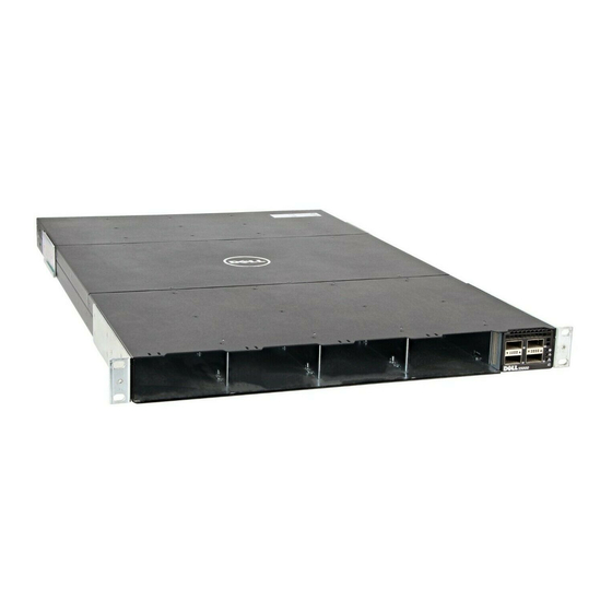
    Wenn Sie einen Switch S5000 bestellen, sind zum Beispiel die folgenden Artikel enthalten. WARNUNG: Sollte ein Artikel fehlen oder beschädigt sein, wenden Sie sich an Ihren Dell Networking Vertreter oder Vertriebspartner. WARNUNG: Wenn die Komponenten falsch gehandhabt werden, können Schäden durch elektrostatische Entladung (ESD) entstehen. Tragen Sie zur ESD-Vorbeugung immer ein Armband oder Absatzriemen zur Erdung beim Umgang mit dem S5000 und den dazugehörigen Komponenten.
  • Seite 53 Entfernen Sie das gesamte Verpackungsmaterial. Untersuchen Sie den Switch und das Zubehör auf Schäden. Wichtige Informationen bevor Sie fortfahren • Machen Sie sich mit dem E/A- und dem Einschubbereich am Gehäuse vertraut. Der E/A-Bereich hat vier Ports mit 40 GbE auf der rechten Seite des Bereichs, siehe Abbildung 1.
  • Seite 54: Übersicht Über Die Hardware-Installation

    Übersicht über die Hardware-Installation Führen Sie zur Installation des S5000 die folgenden Schritte aus: Bringen Sie die Montagehalterungen an. Installieren Sie das S5000-Gehäuse in einem 4-Pfosten-Rack oder -Gehäuse. Erden Sie das Rack. Installieren Sie die Ethernet- und/oder Fibre Channel-Module (ein Fibre Channel- Modul darf nur in Steckplatz 0 installiert werden).
  • Seite 55 – 12-Port-Fibre Channel-Module (2 G/4 G/8G Datendurchsatz) • 4 × 40 GbE QSFP+-Ports und LEDs Abbildung 2. E/A-Bereich des S5000 1. Steckplatz 0 (unterstützt Ethernet- 4. Steckplatz 3 (unterstützt nur und Fibre Channel-Module) Ethernet-Module) 2. Steckplatz 1 (unterstützt nur 5. Vier 40 GbE QSFP+-Ports (jeder Port Ethernet-Module) unterstützt AUSSERDEM den 4 ×...
  • Seite 56 1. Steckplatz 0 (für 4. Steckplatz 3 (für Stromversorgungseinheit 0) Stromversorgungseinheit 1) 2. Steckplatz 1 (für Lüftermodul 0) 5. Griffe 3. Steckplatz 2 (für Lüftermodul 1) Netzteile Der S5000 unterstützt zwei bei laufendem Betrieb austauschbare Stromversorgungseinheiten. ANMERKUNG: Die Stromversorgungseinheit muss vor Ort installiert werden. Der S5000 hat SKU, die die folgenden Konfigurationen unterstützen: •...
  • Seite 57: Konventionen Für Die Portnummerierung

    Konventionen für die Portnummerierung Geradzahlig nummerierte Ports befinden sich am unteren Rand der E/A-Platine und für Module ungeradzahlige Ports befinden sich am oberen Rand der E/A-Platine. Abbildung 4. Portnummerierung Die vorherige Abbildung zeigt die vier festen 40GbE-Datenports (Ports 48, 52, 56, und 60) und die vier Steckplätze für einsteckbare Module im E/A-Bereich des S5000.
  • Seite 58 Wie in der folgenden Abbildung gezeigt, weist der S5000 LEDs an der E/A- und Einschubseite des Gehäuses auf. Wenn der S5000 hochfährt oder eingeschaltet wird, leuchtet die Status-LED an den Stromversorgungen ununterbrochen grün auf. Die folgende Tabelle enthält eine Liste der LED-Definitionen für das S5000-System. Abbildung 5.
  • Seite 59 1. Positionssignal-LED 2. Alarm-LED 3. Systemstatus-LED Tabelle 11. System-LEDs (Einschub- und E/A-Bereich) Label LED-Farbe/-Anzeige Beschreibung • • Keine Aktivität Positionssignal-LED • Blau • Systemblinklicht/- positionsgeber • • Kein Alarm Alarm-LED • Durchgängig gelb • Nicht kritischer Alarm • Durchgängig rot •...
  • Seite 60 Abbildung 7. Modul-LEDs 1. Port-Positionssignal-LED 2. Portlink/Vorgangs-LED 3. Modul-Positionssignal-LED 4. Modulstatus-LED ANMERKUNG: Die nach unten und nach oben zeigenden Dreiecke zeigen jeweils die unteren und oberen LEDs an. Tabelle 12. Ethernet-Port/Modul-LEDs Label LED-Farbe/-Anzeige Beschreibung Port-Positionssignal-LED • • Keine Aktivität • Blau •...
  • Seite 61 Label LED-Farbe/-Anzeige Beschreibung Modul-Positionssignal-LED • • Keine Aktivität • Blau • Modulblinklicht/- Positionsgeber Modulstatus-LED • • Modul ist nicht hochgefahren • Durchgängig grün • Modul ist • Gelb hochgefahren • Problem mit Modul erkannt Tabelle 13. Fibre Channel Port/Modul-LEDs Label LED-Farbe/-Anzeige Beschreibung Port-Positionssignal-LED...
  • Seite 62 Abbildung 8. LEDs für QSFP+-Port 1. Portlink/Vorgangs-LED Tabelle 14. 40 GbE-Port/Modul-LEDs Label LED-Farbe/-Anzeige Beschreibung Portlink/Vorgangs-LED • • Kein Link oder Schnittstelle • Durchgängig grün deaktiviert • Grün, blinkend • Link vorhanden und Schnittstelle aktiviert • Port ist aktiv Installation Überprüfen Sie vor der Installation des Switch die Einhaltung der folgenden Richtlinien: •...
  • Seite 63: Installieren Des S5000-Gehäuses In Einem Rack Oder Schrank

    Verschmutzungen führen kann, was wiederum eine Fehlfunktion des Systems bedingen kann. Installieren des S5000-Gehäuses in einem Rack oder Schrank Für die Installation des S5000-Systems empfiehlt Dell Networking das Ausführen der Installationsvorgänge in der hier dargestellten Reihenfolge. ANMERKUNG: Gehen Sie immer vorsichtig mit dem System und seinen Komponenten um.
  • Seite 64: Sicherheitshinweise Zur Rack-Montage

    Abbildung 9. Schieben Sie die Montagehalterungen ein. 1. Einschubseite des Gehäuses 2. Montagehalterung 3. Halterung (vom Hersteller installiert) Sicherheitshinweise zur Rack-Montage Sie können den Switch entweder in das Rack-Fach stellen oder den Switch direkt in ein 19 Zoll breites, EIA-310-E-konformes Rack einschieben. •...
  • Seite 65: Installieren Des S5000-Gehäuses In Einem 4-Pfosten-Rack Oder - Gehäuse

    Installieren des S5000-Gehäuses in einem 4-Pfosten-Rack oder - Gehäuse ANMERKUNG: Dell Networking empfiehlt, dass eine Person das S5000-Gehäuse in Position hält, während eine zweite Person die Haltebügel an den Pfosten befestigt. Befestigen Sie die Haltebügel mit zwei Schrauben je Bügel am Rack oder...
  • Seite 66 Abbildung 10. Installation des vorderen Racks 1. Schrauben 2. 4–Pfosten-Rack oder -Gehäuse 3. Montagehalterung Rack-Erdung Wenn Sie das Geräte-Rack vorbereiten, stellen Sie sicher, dass das Rack geerdet ist. Das Geräte-Rack muss an dem Erdungspunkt geerdet sein, der auch für die Stromversorgung in diesem Bereich verwendet wird.
  • Seite 67 WARNUNG: Wenn die Komponenten falsch gehandhabt werden, können Schäden durch elektrostatische Entladung (ESD) entstehen. Tragen Sie zur ESD-Vorbeugung immer ein Armband oder Absatzriemen zur Erdung beim Umgang mit dem S5000 und den dazugehörigen Komponenten. ANMERKUNG: Der Teilename und die Portnummer sind auf dem Griff des Ethernet- Moduls vermerkt, siehe folgende Abbildung:...
  • Seite 68 ANMERKUNG: Eine blaue Freigabevorrichtung zeigt an, dass das Ethernet-Modul einen Austausch bei laufendem Switch-Betrieb nicht unterstützt. Bei einem Austausch muss der Switch heruntergefahren werden, bevor das Ethernet-Modul entfernt und ersetzt werden kann. Eine rote Freigabevorrichtung zeigt an, dass das Ethernet-Modul bei laufendem Switch-Betrieb ausgetauscht werden kann. Abbildung 11.
  • Seite 69: Installieren Eines Ethernet-Moduls

    Installieren eines Ethernet-Moduls Verwenden Sie den Haltegriff am Ethernet-Modul, um es in den Modulsteckplatz des Switch einzuschieben. Verbinden Sie alle Netzwerkschnittstellenkabel mit dem eingeschobenen Modul. Abbildung 12. Installieren eines Ethernet-Moduls 1. Freigabevorrichtung 2. Ethernet-Modul Wichtige Informationen für die Installation eines Fibre Channel- Moduls •...
  • Seite 70 • Der S5000 unterstützt den Austausch eines einsteckbaren Fibre Channel-Moduls bei laufendem Switch-Betrieb nicht. Der Switch muss vor dem Entfernen und Ersetzen eines Fibre Channel-Moduls heruntergefahren werden. WARNUNG: Wenn die Komponenten falsch gehandhabt werden, können Schäden durch elektrostatische Entladung (ESD) entstehen. Tragen Sie zur ESD-Vorbeugung immer ein Armband oder Absatzriemen zur Erdung beim Umgang mit dem S5000 und den dazugehörigen Komponenten.
  • Seite 71: Installieren Eines Fibre Channel-Moduls

    ANMERKUNG: Der Teilename und die Portnummer eines Fibre Channel-Moduls sind wie unten beschrieben auf dem Griff vermerkt. Abbildung 13. Teilename und Portnummer auf dem Griff des Fibre Channel-Moduls 1. Teilename 2. Schnittstellennummer Installieren eines Fibre Channel-Moduls Verwenden Sie den Haltegriff am Fibre Channel-Modul, um es in den Einschub des Switch-Moduls einzuschieben.
  • Seite 72 Abbildung 14. Installieren eines Fibre Channel-Moduls 1. Freigabevorrichtung 2. Fibre Channel-Modul Wichtige Informationen für das Installieren eines Wechselstromnetzteils • Das Netzteil gleitet sanft in den Steckplatz. Führen Sie ein Netzteil nicht mit Gewalt in einen Steckplatz ein, da dies das Netzteil oder das S5000-Gehäuse beschädigen kann.
  • Seite 73: Installieren Eines Wechselstrom-Netzteils

    WARNUNG: Obwohl der Switch mit einem einzigen Netzteil betrieben werden kann, empfiehlt Dell Networking den Einsatz von zwei Netzteilen, um eine vollständige Redundanz und ordnungsgemäße Kühlung zu gewährleisten. Wenn der Switch eine Zeit lang mit nur einem Netzteil betrieben werden muss, bedecken Sie die Einschuböffnung des zweiten Netzteils mit einer leeren Blindplatte, um eine...
  • Seite 74 eingeschoben werden kann. Wenn Sie das Netzteil ordnungsgemäß installieren, rastet es ein und ist bündig mit der Rückseite des Switch. Abbildung 15. Installieren eines Wechselstrom-Netzteils 1. Steckplatz 0 (für Wechselstrom-Netzteil 0) 2. Freigabevorrichtung Verbinden Sie das AC3-Steckerkabel des Switch-Netzteils mit der externen Energiequelle (Wechselstrom-Steckdose).
  • Seite 75 Abbildung 16. Verbinden der Wechselstrom-Netzteilkabel 1. AC3-Stecker ANMERKUNG: Das System wird hochgefahren, sobald Sie das Stromkabel zwischen System und Energiequelle verbinden. VORSICHT: Trennen Sie immer das Netzteilkabel, bevor Sie die Stromversorgungssteckplätze warten. VORSICHT: Verwenden Sie das Netzteilkabel, um die Stromzufuhr zum Gerät zu trennen.
  • Seite 76: Zusammenbauen Und Verbinden Des Schutzerdungskabels Für Das Gleichstrom-Netzteil

    Sicherheitserdung selbst herzustellen. Alle elektrischen Verkabelungen müssen den zutreffenden lokalen oder nationalen Regeln und Verfahren entsprechen. Schäden durch nicht von Dell genehmigte Wartungsversuche werden nicht durch die Garantie abgedeckt. Entfernen Sie die Isolierung an den Enden der grünen/gelben Kupferkabel auf einer Länge von ca.
  • Seite 77 Abbildung 17. Zusammenbauen und Verbinden des Schutzerdungskabels für das Gleichstrom-Netzteil 1. Schutzerdungsleiter 4. Federunterlegscheibe 2. Erdungspfosten 5. #6–32-Mutter 3. Unterlegscheibe Wichtige Informationen für das Installieren eines Gleichstrom- Netzteils • Entfernen Sie bei Verwendung eines Gleichstrom-Netzteils den Gleichstromaufkleber und bringen Sie ihn auf dem Hauptkontrollaufkleber am unteren Teil des S5000-Gehäuses an.
  • Seite 78 S5000-Switch). WARNUNG: Obwohl der Switch mit einem einzigen Netzteil betrieben werden kann, empfiehlt Dell Networking den Einsatz von zwei Stromversorgungseinheiten, um eine vollständige Redundanz und ordnungsgemäße Kühlung zu gewährleisten. Wenn der Switch eine Zeit lang mit nur einem Netzteil betrieben werden muss, bedecken Sie die Einschuböffnung des zweiten Netzteils mit einer Blindplatte, um...
  • Seite 79: Installieren Eines Gleichstrom-Netzteils

    VORSICHT: Mischen Sie die Luftstromrichtungen NICHT. Die Luftstromrichtungen sind farblich gekennzeichnet. Eine rote Markierung zeigt an, dass heiße Luft aus dem Netzteil ausgestoßen wird und eine blaue Markierung zeigt an, dass heiße Luft aus dem E/A-Bereich ausgestoßen wird. Beide Lüfter müssen die gleiche Luftstromrichtung verwenden (E/A- zu Einschubbereich oder Einschub- zu E/A- Bereich).
  • Seite 80 Abbildung 18. Installieren eines Gleichstrom-Netzteils 1. Steckplatz 0 (für Wechselstrom-Netzteil 0) 2. Freigabevorrichtung Entfernen Sie die Isolierung der Kupfer-Gleichstromkabel und legen Sie ca. 13 mm (0,5 Zoll) frei. WARNUNG: Durch das Vertauschen der Polung beim Anschluss der Gleichstromkabel kann das Netzteil oder das System dauerhaft beschädigt werden.
  • Seite 81 Abbildung 19. Eingangs-Gleichstromkabel montieren 1. Gleichstrom-Steckdose 5. Kabel (-48V) 2. Gummiabdeckung 6. Kabel RTN 3. Unverlierbare Schrauben (2) 7. Erdungskabel 4. Gleichstrom- Anschlussstecker ANMERKUNG: Das System wird hochgefahren, sobald das Stromkabel zwischen System und Stromquelle verbunden wird. VORSICHT: Trennen Sie immer das Stromversorgungskabel, bevor Sie die Stromversorgungssteckplätze warten.
  • Seite 82: Installieren Des Ferritkerns Für Gleichstrom- Und Stromrückleitungskabel

    Installieren des Ferritkerns für Gleichstrom- und Stromrückleitungskabel Fügen Sie dem Gleichstrom- und Stromrückleitungskabel des Mastermoduls einen Ferritkern hinzu. Installieren Sie den Kern mit einer einfachen Wicklung. Öffnen Sie den Ferritkern mit den Vertiefungen nach oben. Wickeln Sie die Gleichstrom- und Stromrückleitungskabel zweimal um den Ferritkern, wenn zwei Kabelwicklungen in den Ferritkern passen.
  • Seite 83 Abbildung 21. Befestigen der Stromversorgungskabel Verbinden Sie die anderen Enden der Netzstromkabel jeweils mit einer geerdeten Steckdose oder einer separaten Stromquelle wie z. B. einer unterbrechungsfreien Stromversorgung (USV) oder einem Stromverteiler (PDU). ANMERKUNG: Stellen Sie sicher, dass das System an eine eigenständige Stromquelle mit stabiler Stromversorgung angeschlossen ist, um eine optimale Leistung zu gewährleisten.
  • Seite 84: Installieren Eines Lüftermoduls

    Freiraum von mindestens 5 Zoll (12,7 cm) gegeben ist. Wenn Sie zwei S5000- Systeme in geringem Abstand zueinander installieren, platzieren Sie die beiden Gehäuse in einem Abstand von mindestens 5 Zoll (12,7 cm), um einen ordnungsgemäßen Luftstrom zu gewährleisten. Die zulässigen Technische Daten aufgeführt.
  • Seite 85 Ports. Eine Liste der unterstützten Optik finden Sie auf dem S5000-Datenblatt: http:// www.dell.com/us/enterprise/p/force10-s-series/pd . VORSICHT: Wenn die Komponenten falsch gehandhabt werden, können Schäden durch elektrostatische Entladung (ESD) entstehen. Tragen Sie zur ESD-Vorbeugung immer ein Armband oder einen Absatzriemen zur Erdung beim Umgang mit dem...
  • Seite 86 Der S5000 ermöglicht Ihnen, mit einer der unterstützen Kabelpeitschen, einen einzigen 40GbE QSFP+-Port in vier 10GbE SFP+-Ports aufzuteilen. http:// Eine Liste der unterstützten Optik finden Sie auf dem S5000-Datenblatt: www.dell.com/us/enterprise/p/force10-s-series/pd. • Konfigurieren Sie das Gerät, sodass es die Änderung des Port-Modus erkennt. Modus CONFIGURATION (Konfiguration) stack-unit unit-number port number portmode quad stack-unit<unit-number>...
  • Seite 87: Stromversorgung Und Einschalten Des Systems

    System eingeschaltet ist, erkennt das System dieses Modul nicht. Das Ersetzen von Modulen bei eingeschaltetem System kann zu schwerwiegenden Störungen führen. Dell Networking empfiehlt Ihnen, Ihr System immer vor dem Einschalten zu überprüfen. Überprüfen Sie Folgendes: •...
  • Seite 88: Netzstromversorgung

    Netzstromversorgung VORSICHT: Stellen Sie sicher, dass das Netzteil richtig installiert wurde. Die Netzsteckdose muss sich links vom Netzteil befinden und die LED-Statusleuchte oben auf dem Netzteil. Schließen Sie den Stecker an die jeweilige Netzsteckdose an. Stellen Sie sicher, dass das Netzkabel gesichert ist. Sobald der S5000 durch das Kabel mit der Stromquelle verbunden wird, schaltet sich das Gehäuse ein;...
  • Seite 89: Zugriff Auf Den Rj-45/Rs-232-Konsolenport

    11. Weisen Sie einem VLAN eine IP-Adresse zu. 12. Verbinden Sie den S5000 mit dem Netzwerk. Zugriff auf den RJ-45/RS-232-Konsolenport ANMERKUNG: Stellen Sie vor dem Start dieses Vorgangs sicher, dass ein Terminal- Emulationsprogramm auf Ihrem PC-System installiert ist. Der DB9 RS-232/RJ-45-Konsolen-Port befindet sich unten links am S5000, wenn Sie auf den Einschubbereich des Gehäuses blicken.
  • Seite 90: Zugriff Auf Den Rj-45-Konsolenport Mit Einem Db-9-Adapter

    Zugriff auf den RJ-45-Konsolenport mit einem DB-9-Adapter Sie können eine Verbindung zu der Konsole aufbauen, indem Sie ein RJ-45-auf-RJ-45 Rollover-Kabel und einen RJ-45-auf-DB-9 DTE-Adapterstecker mit einem Terminalserver (z. B. einem PC) verbinden. Die Pin-Belegungen zwischen der Konsole und einem DTE-Terminalserver sind wie folgt: Tabelle 15.
  • Seite 91 Abbildung 24. USB-B-Konsolen-Port-Stecker Schalten Sie den PC ein. Installieren Sie die notwendigen USB-Gerätetreiber (dazu benötigen Sie eine Internetverbindung). Wenn sie Hilfe benötigen, kontaktieren Sie den Dell Networking Technical Support. Verbinden Sie das USB-A-Ende des Kabels mit einem freien USB-Port des PCs.
  • Seite 92: Konfigurieren Des Aktivierungskennworts

    (Geheimschlüssel aktivieren) – speichert das Kennwort in der laufenden/Startkonfiguration mithilfe einer wirksameren MD5- Verschlüsselungsmethode. ANMERKUNG: Dell Networking empfiehlt die Verwendung eines Kennworts vom Typ enable secret (Geheimschlüssel aktivieren). • Erstellen Sie ein Kennwort für den Zugriff auf den EXEC-Berechtigungsmodus.
  • Seite 93: Konfigurieren Eines Host-Namens

    – 7 bedeutet, dass Sie ein bereits durch einen DES-Hash verschlüsseltes Kennwort eingeben. Das verschlüsselte Kennwort finden Sie in der Konfigurationsdatei eines anderen Dell Networking Systems. – 5 bedeutet, dass Sie ein bereits durch einen MD5-Hash verschlüsseltes Kennwort eingeben. Das verschlüsselte Kennwort finden Sie in der Konfigurationsdatei eines anderen Dell Networking Systems.
  • Seite 94: Konfigurieren Der Verwaltungsport-Ip-Adresse

    Switching- oder Layer 2-Protokolle einer Schnittstelle, wie das Spanning-Tree-Protokoll (STP), nur konfigurieren, wenn die Schnittstelle im Layer 2-Modus ist. Aktivieren Sie die Schnittstelle. Modus INTERFACE (Schnittstelle) no shutdown Versetzen Sie die Schnittstelle in den Layer 2 (Switching-)Modus. Modus INTERFACE (Schnittstelle) switchport Verwenden Sie zur Anzeige der Schnittstellen im Layer 2-Modus den Befehl show interfaces switchport im EXEC-Modus.
  • Seite 95: Konfigurieren Eines Benutzernamens Und Eines Kennworts

    Standardwert und ist nicht erforderlich. – 0 bedeutet, dass Sie das Kennwort unverschlüsselt eingeben. – 7 bedeutet, dass Sie ein bereits durch einen Typ-7-Hash verschlüsseltes Kennwort eingeben. Das verschlüsselte Kennwort finden Sie in der Konfigurationsdatei eines anderen Dell Networking Systems.
  • Seite 96: Erstellen Eines Portbasierten Vlans

    Erstellen eines portbasierten VLANs Das standardmäßige Virtual Local Area Network (VLAN) (VLAN 1) ist Teil der Systemstartkonfiguration und erfordert keine Konfiguration. Um ein portbasiertes VLAN zu konfigurieren, erstellen Sie das VLAN und fügen Sie dem VLAN anschließend physische Schnittstellen oder Port-Kanal (LAG-)Schnittstellen hinzu. •...
  • Seite 97 interface vlan vlan-id Aktivieren Sie eine Schnittstelle, die den IEEE 802.1Q Tag-Header enthalten soll. Modus INTERFACE (Schnittstelle) tagged Schnittstelle Um nicht markierte Schnittstellen vom Standard-VLAN auf ein anderes VLAN zu verschieben, verwenden Sie den Befehl untagged. Greifen Sie auf den INTERFACE VLAN-Modus des VLANs zu, dem Sie die Schnittstelle zuweisen wollen.
  • Seite 98: Verbinden Des S5000 Mit Dem Netzwerk

    Verbinden des S5000 mit dem Netzwerk Sobald Sie die Hardwareinstallation und Softwarekonfiguration für das S5000-System abgeschlossen haben, können Sie eine Verbindung mit Ihrem Firmennetzwerk herstellen, indem Sie die Verkabelungsrichtlinien Ihres Unternehmens befolgen. Abbildung 25. RJ-45-Netzwerk-/Verwaltungs-Port Technische Daten ANMERKUNG: Achten Sie darauf, dass das Produkt nicht bei einer Umgebungstemperatur von mehr als 40 °C betrieben wird.
  • Seite 99 Parameter Technische Daten • Rückseite: 5 Zoll (12,7 cm) Tabelle 17. Umgebungsparameter Parameter Technische Daten Betriebstemperatur 32 bis 104 °F (0 bis 40 °C) Luftfeuchtigkeit bei Betrieb 10 bis 85 Prozent (RH), nicht kondensierend Lagerungstemperatur –40 bis 158 °F (–40 bis 70 °C) Luftfeuchtigkeit bei Lagerung 5 bis 95 Prozent (RH), nicht kondensierend Relative Luftfeuchtigkeit...
  • Seite 101 Dell Networking S5000 Guía de introducción...
  • Seite 102 AVISO: Un mensaje de AVISO indica el riesgo de daños materiales, lesiones corporales o incluso la muerte. © 2013 Dell Inc. Marcas comerciales utilizadas en este texto: Dell , el logotipo de Dell, Dell Boomi Dell Precision ™...
  • Seite 103: Guía De Introducción

    Para obtener información acerca de la configuración y supervisión de las funciones del FTOS Configuration Guide for the S5000 Switch (Guía de conmutador, consulte la configuración de FTOS para el conmutador S5000), disponible en el sitio web de Dell http://www.dell.com/support/manuals . Support en Descripción del producto...
  • Seite 104: Desembalaje Del Conmutador

    S5000, los siguientes artículos deberían estar incluidos. AVISO: Si falta algún artículo o algún artículo está dañado, póngase en contacto con el representante o distribuidor de Dell Networking para obtener instrucciones. AVISO: Pueden producirse daños por descarga electrostática (ESD) si no se utilizan bien los componentes.
  • Seite 105 Contrato de licencia de software • Coloque el paquete en una superficie plana y limpia y corte todas las cintas que lo sujetan. Abra el paquete o quite la parte superior del mismo. Saque todos los componentes del paquete con mucho cuidado y colóquelos en una superficie limpia y segura.
  • Seite 106 1. Panel de E/S 2. Panel de Utilidad 3. Cuatro puertos QSFP+ de 40 GbE (cada puerto también admite el modo 4 × 10 GbE) Descripción general de la instalación del hardware Para instalar el S5000, siga estos pasos: Fije los soportes de montaje. Instale el chasis S5000 en un gabinete o bastidor de cuatro postes.
  • Seite 107 • Módulos acoplables – Módulo Ethernet de 12 puertos (velocidades de 1 G/10 G) – Módulo Fibre Channel de 12 puertos (velocidades de 2 G/4 G/8 G) • 4 puertos QSFP+ de 40 GbE y diodos emisores de luz (LED) Ilustración 2.
  • Seite 108: Fuentes De Alimentación

    1. Ranura 0 (para la PSU 0) 4. Ranura 3 (para la PSU 1) 2. Ranura 1 (para el módulo de 5. Asas ventilador 0) 3. Ranura 2 (para el módulo de ventilador 1) Fuentes de alimentación El S5000 admite dos PSU de intercambio directo. NOTA: Las PSU se deben instalar en las instalaciones del cliente.
  • Seite 109 Convención de numeración de puertos Los puertos de números pares están en la parte inferior del panel de E/S y para los módulos, los puertos de números impares están en la parte superior del panel de E/S. Ilustración 4. Numeración de puertos En la figura anterior se muestran los cuatro puertos de datos de 40 GbE fijos (puertos 48, 52, 56 y 60) y las cuatro ranuras para los módulos acoplables en el panel de E/S del S5000.
  • Seite 110 Configuration Guide for the S5000 Switch (Guía de configuración de FTOS para el conmutador S5000) . Según se muestra en la siguiente figura, el S5000 incluye indicadores LED en el lateral de E/S y de utilidad del chasis. Cuando el S5000 se enciende o se vuelve a cargar, el LED de estado de los suministros de energía se iluminan con una luz verde fija.
  • Seite 111 1. LED de señalización de ubicación 2. LED de alarma 3. LED de estado del sistema Tabla 20. Indicadores LED del sistema (panel de utilidad y de E/S) Etiqueta Color del LED/indicador Descripción LED de señalización de • Off (Desactivado) •...
  • Seite 112 Etiqueta Color del LED/indicador Descripción LED de estado del • Verde fijo • Funcionamiento ventilador normal • Off (Desactivado) • La alimentación no está presente Ilustración 7. LED de módulo 1. LED de señalización de ubicación de puertos 2. LED de actividad/enlace de puerto 3.
  • Seite 113 Etiqueta Color del LED/indicador Descripción • Señalización/ ubicación de puertos LED de actividad/enlace de • Off (Desactivado) • No hay enlaces o puerto interfaz • Verde fijo deshabilitada • Verde parpadeante • Enlace presente e interfaz habilitada (módulo Ethernet) • El puerto tiene actividad LED de señalización de...
  • Seite 114 Etiqueta Color del LED/indicador Descripción • El puerto tiene actividad LED de señalización de • Off (Desactivado) • Sin actividad ubicación de módulos • Verde • Señalización/ ubicación de módulos LED de estado de módulo • Off (Desactivado) • El módulo no está encendido •...
  • Seite 115: Instalación

    Instalación del chasis S5000 en un bastidor o gabinete Para instalar el sistema S5000, Dell Networking recomienda que complete los procedimientos de instalación en el orden que se señala en este capítulo. NOTA: Maneje siempre el sistema y sus componentes con cuidado. No deje caer el...
  • Seite 116 NOTA: Para conseguir una correcta ventilación, coloque el chasis S5000 en un bastidor para equipos (o gabinete) con un mínimo de 5 pulgadas (12,7 cm) de espacio libre alrededor de las rejillas de ventilación. Los intervalos de temperatura Parámetros medioambientales . ambiente aceptables se muestran en la sección PRECAUCIÓN: Lleve siempre una correa de conexión a tierra en la muñeca o el tobillo para evitar descargas electrostáticas mientras utilice el S5000 y sus...
  • Seite 117 3. Soporte de sujeción (instalado en fábrica) Consideraciones sobre la seguridad del montaje del bastidor Puede colocar el conmutador en el estante del bastidor o montarlo directamente en un bastidor de 19" de ancho, compatible con EIA-310-E. • Carga del bastidor: la sobrecarga o la carga que no sea uniforme de los bastidores puede dar lugar a problemas en el estante o bastidor, provocando daños en el equipo y posibles lesiones corporales.
  • Seite 118 Instalación del chasis S5000 en un gabinete o bastidor de cuatro postes NOTA: Dell Networking recomienda que una persona sostenga el chasis S5000 mientras otra coloca los soportes en los postes. Coloque las "orejetas" del soporte en los postes del gabinete o bastidor con dos tornillos para cada soporte.
  • Seite 119 Conexión a tierra del bastidor Cuando prepare el bastidor del equipo, asegúrese de que esté conectado a tierra. El bastidor del equipo debe estar conectado a tierra en el mismo punto utilizado por la compañía eléctrica de su zona. La conexión a tierra debe ser permanente. Puntos importantes a tener en cuenta al instalar un módulo Ethernet •...
  • Seite 120 NOTA: Un seguro de liberación de color azul indica que el módulo Ethernet no admite el intercambio directo durante las operaciones de conmutación, por lo que deberá apagar el conmutador antes de extraer o sustituir un módulo Ethernet. En cambio, un seguro de liberación de color rojo indica que el módulo Ethernet admite el intercambio directo durante las operaciones de conmutación.
  • Seite 121 Instalación de un módulo Ethernet Utilice el asa del módulo Ethernet para deslizarlo en la ranura para el módulo del conmutador. Conecte los cables de interfaz de red al módulo conectado. Ilustración 12. Instalación de un módulo Ethernet 1. Seguro de liberación 2.
  • Seite 122 AVISO: Pueden producirse daños por descarga electrostática (ESD) si no se utilizan bien los componentes. Lleve siempre una correa de conexión a tierra en la muñeca o el tobillo para evitar descargas electrostáticas mientras utilice el S5000 y sus componentes. NOTA: El nombre de pieza y el número de puerto de los módulos Fibre Channel aparecen en el asa, tal y como se muestra a continuación.
  • Seite 123 Instalación de un módulo Fibre Channel Utilice el asa del módulo Ethernet para deslizarlo en la ranura para el módulo del conmutador.. Conecte los cables de interfaz de red al módulo conectado. Ilustración 14. Instalación de un módulo Fibre Channel 1.
  • Seite 124 FTOS para el conmutador S5000). AVISO: Aunque el conmutador funciona en una sola PSU, Dell Networking recomienda encarecidamente que utilice dos PSU para obtener una redundancia total y una refrigeración adecuada. Si el conmutador se usa con una sola PSU durante un tiempo, asegúrese de tapar la abertura de la ranura de la segunda PSU...
  • Seite 125 Instalación de un suministro de energía de CA Retire la PSU de la bolsa electrostática. Utilice el asa para deslizar la PSU en la ranura para la PSU del conmutador (instale primero el conector de borde de PCB expuesto a PSU). La ranura de la PSU está adaptada de forma que solo se puede insertar de una manera.
  • Seite 126 Ilustración 16. Conexión de los cables de suministro de energía de CA 1. 3 clavijas CA NOTA: El sistema se enciende tan pronto como conecte el cable de alimentación entre el sistema y la fuente de alimentación. PRECAUCIÓN: Desconecte siempre el cable de alimentación antes de realizar tareas de mantenimiento en las ranuras de suministro de energía.
  • Seite 127 CC ni instalar tomas de tierra por su cuenta. Todo el cableado eléctrico debe cumplir las normativas y las prácticas locales y nacionales aplicables. La garantía no cubre los daños ocasionados por reparaciones que Dell Networking no haya autorizado.
  • Seite 128 Ilustración 17. Ensamblaje y conexión del cable de toma a tierra de seguridad para suministros de energía de CC 1. Cable de toma a tierra de 4. Arandela de rosca seguridad 5. Tuerca 6/32 2. Poste de conexión a tierra 3.
  • Seite 129 FTOS Configuration Guide for the S5000 Switch (Guía de configuración de FTOS para el conmutador S5000). AVISO: Aunque el conmutador funciona en una sola PSU, Dell Networking recomienda encarecidamente que utilice dos PSU para obtener una redundancia total y una refrigeración adecuada. Si el conmutador se usa con una sola PSU durante un tiempo, asegúrese de tapar la abertura de la ranura de la segunda PSU...
  • Seite 130 PRECAUCIÓN: NO mezcle direcciones de flujo de aire distintas. Las direcciones de flujo de aire están codificadas mediante un color. Una etiqueta roja indica que el aire caliente se expulsa de la PSU, mientras que una etiqueta azul indica que el aire se expulsa de la E/S.
  • Seite 131 Ilustración 18. Instalación de un suministro de energía de CC 1. Ranura 0 (para PSU de CC 0) 2. Seguro de liberación Quite el aislamiento de los extremos de los cables de alimentación de CC, dejando a la vista unos 13 mm (0,5 pulgadas) de cable de cobre. AVISO: La polaridad inversa al conectar los cables de alimentación de CC puede dañar de forma permanente la fuente de alimentación o el sistema.
  • Seite 132 Ilustración 19. Ensamblaje de los cables de alimentación de entrada de CC 1. Zócalo de alimentación de CC 5. Cable (-48V) 2. Tapa de goma 6. Cable RTN 3. Tornillos cautivos (2) 7. Cable de conexión a tierra 4. Conector de alimentación de NOTA: El sistema se enciende tan pronto como el cable de alimentación se conecta entre el sistema y la fuente de alimentación.
  • Seite 133 Instalación de núcleos de ferrita en los cables de retorno y de alimentación de CC Agregue un núcleo de ferrita a los cables de retorno y de alimentación de CC del módulo maestro. Instale el núcleo con un bucle sencillo. Abra el núcleo de ferrita y coloque la parte hueca mirando hacia arriba.
  • Seite 134 Ilustración 21. Fijación de los cables de alimentación Conecte el otro extremo de los cables de alimentación a una toma de corriente eléctrica con conexión a tierra o a otra fuente de alimentación, como por ejemplo a un sistema de alimentación ininterrumpida (SAI) o a una unidad de distribución de alimentación (PDU).
  • Seite 135 • La velocidad del ventilador aumenta o disminuye de forma automática en función de la temperatura interna. El conmutador nunca apaga los ventiladores intencionadamente. • Para conseguir una ventilación correcta, coloque el S5000 en un bastidor para equipos (o gabinete) con un mínimo de 5 pulgadas (12,7 cm) de espacio libre alrededor de las rejillas de ventilación.
  • Seite 136 Para ver una lista de los puertos ópticos compatibles, consulte la hoja de datos del S5000: http://www.dell.com/us/enterprise/p/force10-s-series/pd . PRECAUCIÓN: Pueden producirse daños por descarga electrostática (ESD) si no se utilizan bien los componentes. Lleve siempre una correa de conexión a tierra en la muñeca o el tobillo para evitar descargas electrostáticas mientras utilice el S5000 y...
  • Seite 137 El S5000 admite la división de un único puerto QSFP+ de 40 GbE en cuatro puertos SFP+ de 10 GbE mediante el uso de uno de los cables breakout admitidos. Para ver una lista de los puertos ópticos compatibles, consulte la hoja de datos del http://www.dell.com/us/enterprise/p/force10-s-series/pd . S5000: •...
  • Seite 138 Si reemplaza el módulo cuando el sistema está encendido, el sistema no reconocerá el módulo. La inserción de los módulos con el sistema encendido puede provocar un error grave. Dell Networking recomienda que se vuelva a inspeccionar el sistema antes de encenderlo. Compruebe que: •...
  • Seite 139 Conecte el enchufe a cada conector de alimentación de CA y compruebe que el cable de alimentación esté asegurado. El chasis se enciende tan pronto como el cable se conecta entre el S5000 y la fuente de alimentación; no existe un interruptor de encendido o apagado. Alimentación de CC Conecte el enchufe a cada toma de CC y compruebe que el cable de alimentación esté...
  • Seite 140 Acceso al puerto de consola RJ-45/RS-232 NOTA: Antes de comenzar este procedimiento, asegúrese de tener un programa de emulación de terminal ya instalado en su PC. El puerto de consola DB9 RS-232/RJ-45 tiene una etiqueta en la parte inferior izquierda del S5000 al mirarlo por el lado de la Utilidad del chasis.
  • Seite 141 Tabla 24. Asignaciones de patillas entre la consola y un servidor de terminal DTE Puerto de Cable invertido Cable invertido Adaptador de Dispositivo de consola del de RJ-45 a de RJ-45 a Cable invertido servidor de S5000 RJ-45 RJ-45 de RJ-45 a terminal RJ-45 a DB-9 Señal...
  • Seite 142 Instale los controladores de dispositivos USB necesarios (se necesita conexión a Internet). Para obtener asistencia, póngase en contacto con la Asistencia técnica de Dell Networking. Conecte el extremo USB-A del cable a un puerto USB disponible del PC. Conecte el extremo USB-B del cable al puerto de consola USB-B del S5000.
  • Seite 143 • enable secret: se almacena en la configuración de ejecución/inicio al utilizar un método de cifrado MD5 más potente. NOTA: Dell Networking recomienda utilizar la contraseña enable secret. • Cree una contraseña para acceder al modo EXEC Privilege (Privilegios de ejecución).
  • Seite 144: Configuración Predeterminada

    El 5 permite introducir una contraseña que ya se ha cifrado mediante un hash MD5. Obtenga la contraseña cifrada del archivo de configuración de otro sistema de Dell Networking. Configuración de un nombre de host El nombre de host aparece en el símbolo del sistema. El nombre de host predeterminado es FTOS.
  • Seite 145 Si desea ver las interfaces en el modo de Capa 2, utilice el comando show interfaces switchport en el modo EXEC. Acceso al sistema de manera remota Puede configurar el sistema para el acceso remoto mediante Telnet. El sistema dispone de un puerto de administración dedicado y de una tabla de enrutamiento de administración independiente a la tabla de enrutamiento IP.
  • Seite 146 El 7 permite introducir una contraseña que ya se ha cifrado mediante un hash de tipo 7. Obtenga la contraseña cifrada de la configuración de otro sistema de Dell Networking. Creación de una VLAN basada en puerto La red de área local virtual predeterminada (VLAN) (VLAN 1) es parte de la configuración de inicio del sistema y no requiere configuración.
  • Seite 147 interface vlan vlan-id Después de crear una VLAN, debe asignar interfaces en el modo de Capa 2 a la VLAN, con el fin de activarla. Para ver las VLAN configuradas, utilice el comando show vlan en el modo EXEC Privilege (Privilegios de ejecución). Asignación de interfaces a una VLAN Solo puede asignar las interfaces del modo de Capa 2 a una VLAN utilizando los comandos tagged y untagged.
  • Seite 148: Especificaciones Técnicas

    untagged interface Asignación de una dirección IP a una VLAN Las redes VLAN son una función de Capa 2. Para que dos interfaces físicas de VLAN diferentes se comuniquen, debe asignar una dirección IP a las VLAN para enrutar el tráfico entre las dos interfaces.
  • Seite 149: Especificaciones

    PRECAUCIÓN: Precaución sobre la batería de litio: se puede producir peligro de explosión si no se coloca la batería correctamente. NOTA: Reemplace la batería solamente por otras del mismo tipo o de un tipo equivalente. Deseche la batería según las instrucciones del fabricante. Tabla 25.
  • Seite 150 Tabla 27. Requisitos de alimentación Parámetro Especificaciones Suministro de energía de CA De 100 V CA a 240 V CA, 50/60 Hz Suministro de energía de CC De –48 V a –60 V V CC 7 A a 100 V CA Toma máxima de corriente por sistema 3,5 A a 200 V CA Máximo consumo de energía...
  • Seite 151 Dell Networking S5000 Guide de mise en route...
  • Seite 152 éviter le problème. AVERTISSEMENT : Un AVERTISSEMENT indique un risque d'endommagement du matériel, de blessure corporelle ou de mort. © 2013 Dell Inc. Marques utilisées dans ce document : Dell , le logo Dell, Dell Boomi , Dell Precision , OptiPlex ™...
  • Seite 153: Guide De Mise En Route

    Guide de configuration FTOS du commutateur S5000 , disponible sur le reportez-vous au http://www.dell.com/support/manuals . site Web de support Dell à l'adresse Description du produit Le S5000 fait partie des commutateurs S-Series pour commutateurs ToR (Top of Rack) de centres de données de Dell Networking.
  • Seite 154: Déballage Du Commutateur

    éléments suivants. AVERTISSEMENT : Si un ou plusieurs éléments sont manquants ou endommagés, contactez votre représentant Dell Networking ou revendeur pour des instructions. AVERTISSEMENT : Un dommage résultant d'une décharge électrostatique peut survenir en cas de mauvaise manipulation de composants. Portez toujours un bracelet antistatique lorsque vous manipulez le S5000 et ses composants.
  • Seite 155 Points importants avant de continuer • Identifiez le panneau d'E/S et de l'utilitaire sur le châssis. Le panneau d'E/S dispose de quatre ports 40 GbE situés sur le côté droit du panneau (voir Figure 1). Le panneau de l'utilitaire comprend les logements des blocs d'alimentation, les voyants et les logements USB, situés sur le côté...
  • Seite 156: Présentation Du Matériel

    Présentation de l'installation du matériel Pour installer le S5000, procédez comme suit : Connectez les supports de montage Installez le châssis S5000 dans un rack à quatre montants ou une armoire. Mettez le rack à la terre. Installez les modules Ethernet et/ou Fibre Channel (le module Fibre Channel doit être installé...
  • Seite 157 – Module Ethernet à 12 ports (vitesses de 1 G/10 G) – Module Fibre Channel à 12 ports (vitesses de 2 G/4 G/8 G) • 4 ports QSFP+ 40GbE et voyants (LED) Figure 2. Panneau d'E/S du S5000 1. Logement 0 (prend en charge les 4.
  • Seite 158: Blocs D'alimentation

    1. Logement 0 (pour la PSU 0) 4. Logement 3 (pour la PSU 1) 2. Logement 1 (pour le module de 5. Poignées de saisie ventilateur 0) 3. Logement 2 (pour le module de ventilateur 1) Blocs d'alimentation Le S5000 prend en charge deux PSU remplaçables à chaud. REMARQUE : Les PSU doivent être installées sur le site du client.
  • Seite 159 Convention de numérotage de ports Les ports pairs se trouvent dans la partie inférieure du panneau E/S et les ports de modules impairs se trouvent dans la partie supérieure du panneau E/S. Figure 4. Numérotage de ports La figure précédente illustre les quatre ports de données 40 GbE fixes (les ports 48, 52, 56 et 60) et les quatre logements destinés aux modules enfichables sur le panneau d'E/S du S5000.
  • Seite 160 Comme le montre la figure suivante, le S5000 dispose de voyants sur le côté E/S et Utilitaire du châssis. Lorsque le S5000 se met sous tension ou se recharge, les voyants d'état des blocs d'alimentation sont vert fixe. La tableau suivant répertorie les définitions des voyants du système S5000. Figure 5.
  • Seite 161 1. Voyant des balises du localisateur 2. Voyant d'alarme 3. Voyant d'état du système Tableau 29. Affichage des voyants du système (panneau de l'utilitaire et des E/S) Étiquette Couleur/Affichage du Description voyant Voyant des balises du • Désactivé • Aucune activité •...
  • Seite 162 Étiquette Couleur/Affichage du Description voyant • Alimentation absente Voyant d'état du ventilateur • Vert fixe • Fonctionnement normal • Désactivé • Alimentation absente Figure 7. Voyants de module 1. Voyant de la balise du localisateur de port 2. Voyant d'activité/de liaison de port 3.
  • Seite 163 Tableau 30. Voyants de port/module Ethernet Étiquette Couleur/Affichage du Description voyant Voyant de la balise du • Désactivé • Aucune activité localisateur de port • Bleu • Balise/localisateur du port Voyant d'activité/de liaison • Désactivé • Aucune liaison ou de port interface •...
  • Seite 164 Étiquette Couleur/Affichage du Description voyant • Le port est actif Voyant de la balise du • Désactivé • Aucune activité localisateur de module • Vert • Balise/localisateur du module Voyant d'état du module • Désactivé • Le module n'est pas sous tension •...
  • Seite 165 Installation du châssis S5000 dans un rack ou une armoire Pour installer le système S5000, Dell Networking recommande de réaliser les procédures d'installation dans l'ordre présenté ici. REMARQUE : Manipulez toujours le système et ses composants avec précaution.
  • Seite 166 PRÉCAUTION : Portez toujours un bracelet antistatique lors de la manipulation du S5000 et de ses composants. Comme avec tous les appareils électriques de ce genre, prenez toutes les mesures nécessaires pour éviter de vous blesser lors de l'installation de ce système. Une mauvaise manipulation des composants peut entraîner des dommages causés par des décharges électrostatiques.
  • Seite 167 Consignes de sécurité de montage en rack Vous pouvez soit placer le commutateur sur l'étagère du rack, soit le monter directement dans un rack d'une largeur de 19 pouces conforme à la norme EIA-310-E. • Chargement dans le rack : surcharger un rack ou le charger de manière non équilibrée peut dégrader l'étagère ou le rack et endommager l'équipement ou causer des blessures corporelles.
  • Seite 168 Installation du châssis S5000 dans une armoire ou rack à quatre montants REMARQUE : Dell Networking recommande qu'une personne maintienne le châssis S5000 en place tandis qu'une deuxième personne relie les supports sur les montants. Reliez les « oreilles » des supports aux montants du rack ou de l'armoire à l'aide deux vis pour chaque support.
  • Seite 169 service d'alimentation de votre emplacement géographique. Cette liaison à la terre doit être permanente. Points importants à ne pas oublier lors de l'installation d'un module Ethernet • L'installation et le remplacement de modules Ethernet doivent être effectués AVANT leur mise sous tension. Si vous avez besoin d'installer ou de remplacer un module, mettez le système hors tension avant de procéder à...
  • Seite 170 REMARQUE : Un loquet de dégagement bleu indique que le module Ethernet ne prend pas en charge le remplacement à chaud lorsque le commutateur est en marche. Vous devez donc mettre le commutateur hors tension avant de retirer ou remplacer un module Ethernet. Un loquet de dégagement rouge indique que le module Ethernet prend en charge le remplacement à...
  • Seite 171 Installation d'un module Ethernet Utilisez la poignée de saisie du module Ethernet pour le faire glisser dans le logement de module du commutateur. Connectez tous les câbles d'interface réseau au module. Figure 12. Installation d'un module Ethernet 1. Loquet de dégagement 2.
  • Seite 172 donc mettre le commutateur hors tension avant de retirer ou de remplacer un module Fibre Channel. AVERTISSEMENT : Un dommage résultant d'une décharge électrostatique peut survenir en cas de mauvaise manipulation de composants. Portez toujours un bracelet antistatique lorsque vous manipulez le S5000 et ses composants. REMARQUE : Le nom de pièce et le numéro de port d'un module Fibre Channel sont inscrits sur la poignée de celui-ci, tel qu'illustré...
  • Seite 173 Installation d'un module Fibre Channel Utilisez la poignée de saisie du module Fibre Channel pour le faire glisser dans le logement de module du commutateur. Connectez tous les câbles d'interface réseau au module. Figure 14. Installation d'un module Fibre Channel 1.
  • Seite 174 S5000 . AVERTISSEMENT : Bien que le commutateur puisse fonctionner avec une seule PSU, Dell Networking recommande vivement d'utiliser deux PSU pour une redondance complète et un refroidissement adéquat. Si le commutateur a besoin de fonctionner avec une seule PSU pendant un temps donné, assurez-vous que vous avez couvert l'ouverture du logement de la deuxième PSU d'un cache pour...
  • Seite 175 Installation d'un bloc d'alimentation en CA Retirez la PSU du sac électrostatique. Utilisez la poignée de saisie de la PSU pour la faire glisser dans le logement de PSU du commutateur (insérez le côté sur lequel se trouve le connecteur Edge de PCB en premier).
  • Seite 176 Figure 16. Connexion des câbles des blocs d'alimentation en CA 1. Broche AC3 REMARQUE : Le système est mis sous tension dès que vous connectez le cordon d'alimentation entre le système et la source d'alimentation. PRÉCAUTION : Déconnectez toujours le câble d'alimentation avant d'effectuer une action de maintenance sur les logements de bloc d'alimentation.
  • Seite 177 Tout le câblage électrique doit être conforme aux pratiques et aux codes locaux et nationaux en vigueur. Tout dommage provoqué par une réparation non autorisée par Dell Networking est exclu de votre garantie. Enlevez la protection isolante de l'extrémité du câble vert/jaune pour exposer environ 4,5 mm (0,175 pouce) de fil de cuivre.
  • Seite 178 Figure 17. Assemblage et connexion du câble de mise à la terre de sécurité pour un bloc d'alimentation en CC 1. Câble de mise à la terre de 4. Rondelle à ressort sécurité 5. Écrou #6–32 2. Boîte de mise à la terre 3.
  • Seite 179 S5000 et Guide de configuration FTOS du commutateur S5000 . AVERTISSEMENT : Bien que le commutateur puisse fonctionner avec une seule PSU, Dell Networking recommande vivement d'utiliser deux PSU pour une redondance complète et un refroidissement adéquat. Si le commutateur a besoin de fonctionner avec une seule PSU pendant un temps donné, assurez-vous que...
  • Seite 180 PRÉCAUTION : NE combinez PAS des flux d'air de différentes directions. Les directions de flux d'air sont codées par couleur. Une étiquette rouge indique que de l'air chaud se dégage de la PSU et une étiquette bleue indique que les E/S dégagent de l'air chaud.
  • Seite 181 Figure 18. Installation d'un bloc d'alimentation en CC 1. Logement 0 (pour la PSU en CC 0) 2. Loquet de dégagement Enlevez la protection isolante de l'extrémité des câbles d'alimentation en CC pour exposer environ 13 mm (0,5 pouce) de fil de cuivre. AVERTISSEMENT : L'inversion de la polarité...
  • Seite 182 Figure 19. Assemblage des câbles d'alimentation d'entrée en CC 1. Support d'alimentation en CC 5. Câble (-48 V) 2. Capuchon en caoutchouc 6. Câble RTN 3. Vis imperdables (2) 7. Câble de terre 4. Connecteur d'alimentation CC REMARQUE : Le système est mis sous tension dès que vous connectez le cordon d'alimentation entre le système et la source d'alimentation.
  • Seite 183 Installation de la bille en ferrite sur les câbles d'alimentation et de retour CC Ajoutez une bille en ferrite sur les câbles d'alimentation et de retour CC du module maître. Installez la bille avec une seule boucle. Ouvrez la bille en ferrite avec les creux vers le haut. Enroulez les câbles d'alimentation et de retour CC autour de la bille en ferrite (deux fois s'il y a assez d'espace) ou fixez simplement la bille sur les deux câbles.
  • Seite 184 Figure 21. Fixation des câbles d'alimentation Branchez ensuite l'autre extrémité des câbles d'alimentation sur une prise de courant mise à la terre ou sur une source d'alimentation autonome (onduleur ou unité de distribution de l'alimentation). REMARQUE : Vérifiez que le système est relié à une source d'alimentation autonome et stable (pour de meilleures performances).
  • Seite 185 Lorsque vous installez deux système S5000 près l'un de l'autre, espacez-les d'au moins 5 pouces (12,7 cm) pour permettre un flux d'air adéquat. Les plages de température ambiante acceptable sont répertoriées dans la section Caractéristiques techniques . • Pour afficher les messages du journal, utilisez la commande show logging (Afficher la journalisation).
  • Seite 186 Pour consulter la liste des modules optiques pris en charge, reportez-vous à la feuille de données du S5000 : http://www.dell.com/us/enterprise/p/force10-s-series/pd . PRÉCAUTION : Des dommages résultant d'une décharge électrostatique peuvent survenir en cas de mauvaise manipulation de composants. Portez toujours un...
  • Seite 187 Le S5000 prend en charge la division d'un port QSFP+ 40 GbE en quatre ports SFP+ 10 GbE à l'aide d'un des câbles de branchement pris en charge. Pour consulter la liste des modules optiques pris en charge, reportez-vous à la feuille de http://www.dell.com/us/enterprise/p/force10-s-series/pd . données du S5000 : •...
  • Seite 188 L'insertion en ligne de modules peut entraîner un échec catastrophique. Dell Networking vous recommande d'inspecter de nouveau votre système avant de le mettre sous tension. Vérifiez que : •...
  • Seite 189: Réalisation De La Configuration Initiale

    Alimentation en CA PRÉCAUTION : Assurez-vous que la PSU est correctement installée. Le connecteur d'alimentation en CA doit se trouver sur le côté gauche de la PSU et le voyant d'état sur le haut. Branchez la prise à chaque connecteur d'alimentation en CA, en vous assurant de sécuriser le cordon d'alimentation.
  • Seite 190 11. Attribuez une adresse IP à un VLAN. 12. Connectez le S5000 au réseau. Accès au port de console RJ-45/RS-232 REMARQUE : Avant de commencer cette procédure, assurez-vous que le programme d'émulation de terminal est déjà installé sur votre ordinateur. Le port de console DB9 RS-232/RJ-45 est étiqueté...
  • Seite 191 Accès au port de console RJ-45 avec un adaptateur DB-9 Vous pouvez vous connecter à la console à l'aide d'un câble de basculement RJ-45 à RJ-45 et d'un adaptateur femelle DTE RJ-45 à DB-9 à un serveur terminal (par exemple, un PC).
  • Seite 192 Figure 24. Connecteur du port de console USB-B Mettez l'ordinateur sous tension. Installez les pilotes de périphériques USB nécessaires (vous aurez besoin d'une connexion Internet). Pour obtenir de l'aide, contactez le support technique Dell Networking. Branchez l'extrémité USB-A du câble dans un port USB disponible de l'ordinateur.
  • Seite 193 : celui-ci est stocké dans la configuration d'exécution/de démarrage à l'aide d'une méthode de cryptage MD5 plus robuste. REMARQUE : Dell Networking vous recommande d'utiliser le mot de passe secret d'activation. • Créez un mot de passe pour accéder au mode EXEC Privilege.
  • Seite 194 7 est pour la saisie d'un mot de passe déjà crypté à l'aide d'un hachage DES. Obtenez le mot de passe crypté depuis le fichier de configuration d'un autre système Dell Networking. – 5 est pour la saisie d'un mot de passe déjà crypté à l'aide d'un hachage MD5.
  • Seite 195 protocol), sur une interface à moins que cette dernière n'ait été configurée sur le mode Layer 2. Activez l'interface Mode INTERFACE no shutdown Mettez l'interface en mode Layer 2 (commutation) Mode INTERFACE switchport Pour afficher les interfaces en mode Layer 2, utilisez la commande show interfaces switchport en mode EXEC.
  • Seite 196 0 est pour la saisie du mot de passe non cryptée. – 7 est pour la saisie d'un mot de passe déjà crypté à l'aide d'un hachage de type 7. Obtenez le mot de passe crypté depuis le fichier de configuration d'un autre système Dell Networking.
  • Seite 197 Création d'un VLAN à base de port Le VLAN par défaut (VLAN 1) fait partie de la configuration de démarrage du système et n'exige aucune configuration. Pour configurer un VLAN à base de port, vous devez créer le VLAN, puis y ajouter des interfaces physiques ou un canal de port (LAG).
  • Seite 198 tagged interface Pour déplacer les interfaces non marquées du VLAN par défaut à un autre VLAN, utilisez la commande untagged. Accéder au mode INTERFACE VLAN du VLAN auquel vous souhaitez attribuer l'interface. Mode CONFIGURATION interface vlan id vlan Configurez une interface comme « non marquée ». Ces commandes sont uniquement disponibles dans les interfaces VLAN.
  • Seite 199: Caractéristiques Techniques

    Connexion du S5000 au réseau Une fois l'installation du matériel et la configuration du logiciel du système S5000 effectuées, vous pouvez vous connecter au réseau de votre entreprise en respectant les exigences de câblage de celle-ci. Figure 25. Port de réseau/gestion RJ-45 Caractéristiques techniques REMARQUE : Faites fonctionner le produit à...
  • Seite 200: Caractéristiques

    Paramètre Caractéristiques • Arrière : 5 pouces (12,7 cm) Tableau 35. Paramètres d'environnement Paramètre Caractéristiques Températures en fonctionnement 32 à 104 °F (0 à 40 °C) Humidité de fonctionnement 10 à 85 % (RH), sans condensation Température de stockage –40 à 158 °F (–40 à 70 °C) Humidité...
  • Seite 201 Dell Networking S5000 ‫עבודה‬ ‫תחילת‬ ‫מדריך‬...
  • Seite 202 ‫שבשימוש‬ ‫מסחריים‬ ‫סימנים‬ KACE Compellent EqualLogic OpenManage PowerConnect PowerVault PowerEdge ™ ™ ™ ™ ™ ™ ™ Dell Inc. Intel , Pentium , Xeon , Core Vostro ‫- ו‬ Force10 FlexAddress ® ® ® ® ™ ™ ™ ‫-ו‬ ‫של‬...
  • Seite 203 ‫היעזר‬ ‫המתג‬ ‫מאפייני‬ ‫של‬ ‫והניטור‬ ‫הקביעה‬ ‫על‬ ‫לפרטים‬ http://www.dell.com/support/manuals S5000 Dell ‫בכתובת‬ ‫של‬ ‫התמיכה‬ ‫באתר‬ ‫שזמין‬ ‫המוצר‬ ‫תיאור‬ Dell Networking S5000 ‫- ה‬ ‫מרכזי‬ ‫עבור‬ ‫עלית‬ ‫להתקנה‬ ‫מתגים‬ ‫הכוללת‬ ‫של‬ ‫מהסדרה‬ ‫מתג‬ ‫הוא‬ ‫נתונים‬ S5000 ‫- ל‬ ‫זהו‬ ‫וירטואליזציה‬ ‫שעברו‬...
  • Seite 204 ‫נשלחים‬ ‫והאביזרים‬ S5000 ‫הפריטים‬ ‫להגיע‬ ‫צריכים‬ ‫אחד‬ ‫מתג‬ ‫הזמנת‬ ‫אם‬ ‫למשל‬ ‫שהזמנת‬ ‫הפריטים‬ ‫את‬ ‫שקיבלת‬ ‫ודא‬ ‫לנזק‬ ‫עדות‬ ‫הבאים‬ Dell Networking ‫כדי‬ ‫של‬ ‫המשווק‬ ‫או‬ ‫הנציג‬ ‫עם‬ ‫קשר‬ ‫צור‬ ‫פגועים‬ ‫או‬ ‫חסרים‬ ‫כלשהם‬ ‫פריטים‬ ‫אם‬ ‫אזהרה‬ ‫לפעול‬ ‫כיצד‬ ‫דרכם‬ ‫לברר‬...
  • Seite 205 2 ‫ו‬ • ‫רק‬ ‫להכניס‬ ‫ניתן‬ ‫כוח‬ ‫ספקי‬ ‫את‬ ‫באיור‬ ‫היעזר‬ ‫השירות‬ ‫בלוח‬ ‫החריצים‬ ‫את‬ ‫זהה‬ - 3 . 0 ‫ו‬ ‫מהחריצים‬ ‫אחד‬ ‫לכל‬ ‫להכניס‬ ‫ניתן‬ ‫האוורור‬ ‫מודולי‬ ‫את‬ ‫לחריצים‬ S5000 ‫- ב‬ ‫השירות‬ ‫ולוח‬ ‫פלט‬ ‫הקלט‬ ‫לוח‬ ‫איור‬ ‫פלט‬ ‫הקלט‬...
  • Seite 206 ‫החומרה‬ ‫סקירת‬ S5000 ‫- ה‬ ‫עבור‬ ‫מודולריות‬ ‫חומרה‬ ‫תצורות‬ ‫ועל‬ ‫ההתקן‬ ‫תכונות‬ ‫על‬ ‫מידע‬ ‫כולל‬ ‫זה‬ ‫סעיף‬ ‫: הן‬ S5000 ‫של‬ ‫הפיזיות‬ ‫המידות‬ ‫( מ‬ ‫" מ‬ 43.5 1.71 • ‫אינץ‬ ‫גובה‬ ‫( מ‬ ‫" מ‬ 441.9 17.4 • ‫אינץ‬ ‫רוחב‬...
  • Seite 207 " ‫א‬ " ‫א‬ ‫והמתח‬ ‫המאוורר‬ ‫סטטוס‬ ‫דפ‬ ‫המעטפת‬ ‫צדי‬ ‫בשני‬ ‫נמצאות‬ ‫המערכת‬ ‫סטטוס‬ ‫עבור‬ ‫הדפ‬ ‫תצוגות‬ ‫הערה‬ ‫השירות‬ ‫בלוח‬ ‫נמצאות‬ ‫השירות‬ ‫לוח‬ ‫המתח‬ ‫ואספקת‬ ‫האוורור‬ ‫של‬ ‫המודולים‬ ‫את‬ ‫כולל‬ ‫הפלטפורמה‬ ‫של‬ ‫השירות‬ ‫לוח‬ ‫צד‬ S5000 ‫- ה‬ ‫של‬ ‫והאוורור‬ ‫הכוח‬...
  • Seite 208 ‫הלקוח‬ ‫באתר‬ ‫להיעשות‬ ‫צריכה‬ ‫המאווררים‬ ‫התקנת‬ ‫היציאות‬ ‫מספור‬ ‫לגבי‬ ‫מוסכמה‬ ‫זוגי‬ ‫אי‬ ‫שמספרן‬ ‫יציאות‬ ‫מודולים‬ ‫ועבור‬ ‫פלט‬ ‫הקלט‬ ‫לוח‬ ‫של‬ ‫התחתון‬ ‫בצד‬ ‫ממוקמות‬ ‫זוגי‬ ‫שמספרן‬ ‫יציאות‬ ‫פלט‬ ‫הקלט‬ ‫לוח‬ ‫של‬ ‫העליון‬ ‫בצד‬ ‫ממוקמות‬ ‫היציאות‬ ‫מספור‬ ‫איור‬ ‫- ו‬ 40GbE ‫החריצים‬ ‫וארבעת‬...
  • Seite 209 " ‫א‬ S5000 , ‫ה‬ ‫או‬ ‫בהדלקה‬ ‫המעטפת‬ ‫של‬ ‫השירות‬ ‫ובצד‬ ‫פלט‬ ‫הקלט‬ ‫בלוח‬ ‫דפ‬ ‫תצוגת‬ ‫כולל‬ ‫שלהלן‬ ‫באיור‬ ‫כמוצג‬ " ‫א‬ S5000 ‫- ב‬ ‫בירוק‬ ‫בקביעות‬ ‫מוארים‬ ‫הכוח‬ ‫בספקי‬ ‫הסטטוס‬ ‫דפ‬ ‫של‬ ‫מחדש‬ ‫הטעינה‬ S5000 " ‫א‬ ‫המערכת‬ ‫עבור‬ ‫הדפ‬...
  • Seite 210 " ‫א‬ ‫המערכת‬ ‫סטטוס‬ ‫דפ‬ " ‫א‬ ‫פלט‬ ‫הקלט‬ ‫ולוח‬ ‫השירות‬ ‫לוח‬ ‫המערכת‬ ‫דפ‬ ‫תצוגות‬ ‫טבלה‬ " ‫א‬ ‫תיאור‬ ‫הדפ‬ ‫תצוגת‬ ‫צבע‬ ‫תווית‬ • • ‫פעילות‬ ‫אין‬ ‫כבויה‬ " ‫א‬ ‫המאתר‬ ‫איתות‬ ‫דפ‬ • • ‫המערכת‬ ‫מאתר‬ ‫איתות‬ ‫כחול‬ • •...
  • Seite 211 " ‫א‬ ‫המודול‬ ‫דפ‬ ‫איור‬ " ‫א‬ ‫היציאות‬ ‫מאתר‬ ‫איתות‬ ‫דפ‬ " ‫א‬ ‫היציאה‬ ‫איתות‬ ‫קישור‬ ‫דפ‬ " ‫א‬ ‫המודולים‬ ‫מאתר‬ ‫איתות‬ ‫דפ‬ " ‫א‬ ‫המודול‬ ‫סטטוס‬ ‫דפ‬ " ‫א‬ ‫בהתאמה‬ ‫והעליונות‬ ‫התחתונות‬ ‫היציאות‬ ‫דפ‬ ‫את‬ ‫מציינים‬ ‫מעלה‬ ‫או‬ ‫מטה‬ ‫כלפי‬...
  • Seite 212 " ‫א‬ ‫תיאור‬ ‫הדפ‬ ‫תצוגת‬ ‫צבע‬ ‫תווית‬ • • ‫דולק‬ ‫המודול‬ ‫קבוע‬ ‫ירוק‬ • • ‫במודול‬ ‫תקלה‬ ‫זוהתה‬ ‫צהוב‬ " ‫א‬ ‫המודול‬ ‫דפ‬ ‫סיבי‬ ‫ערוץ‬ ‫יציאת‬ ‫טבלה‬ " ‫א‬ ‫תיאור‬ ‫הדפ‬ ‫תצוגת‬ ‫צבע‬ ‫תווית‬ " ‫א‬ ‫היציאות‬ ‫מאתר‬ ‫איתות‬ ‫דפ‬ •...
  • Seite 213 ‫מערכת‬ ‫לתקלת‬ ‫להוביל‬ ‫שעשוי‬ ‫המעטפת‬ ‫בתוך‬ ‫זיהום‬ ‫להצטברות‬ ‫ולגרום‬ ‫אחרים‬ ‫וחלקיקים‬ -S5000 ‫ה‬ ‫מעטפת‬ ‫התקנת‬ ‫ארון‬ ‫או‬ ‫במעמד‬ S5000, Dell Networking ‫המערכת‬ ‫של‬ ‫ההתקנה‬ ‫לצורך‬ ‫סדר‬ ‫לפי‬ ‫ההתקנה‬ ‫נוהלי‬ ‫את‬ ‫לבצע‬ ‫ממליצה‬ ‫להלן‬ ‫הופעתם‬ ‫- ה‬ ‫מעטפת‬ ‫את‬ ‫מלהפיל‬ ‫הימנע‬...
  • Seite 214 S5000 ‫- ה‬ ‫עם‬ ‫ההתעסקות‬ ‫בעת‬ ‫למניעת‬ ‫הארקה‬ ‫רצועת‬ ‫העקב‬ ‫או‬ ‫היד‬ ‫פרק‬ ‫סביב‬ ‫תמיד‬ ‫לבש‬ ‫התראה‬ ‫, זה‬ ‫התקנת‬ ‫במהלך‬ ‫הנחוצים‬ ‫הזהירות‬ ‫אמצעי‬ ‫כל‬ ‫את‬ ‫נקוט‬ ‫מסוג‬ ‫החשמליים‬ ‫המכשירים‬ ‫לכל‬ ‫בדומה‬ ‫ורכיביה‬ ‫הרכיבים‬ ‫עם‬ ‫לקויה‬ ‫התעסקות‬ ‫של‬ ‫במקרה‬ ‫להיווצר‬ ‫עשוי‬...
  • Seite 215 ‫ספציפי‬ ‫מתג‬ ‫לייצג‬ ‫נועדו‬ ‫לא‬ ‫במסמך‬ ‫האיורים‬ ‫הערה‬ -S5000 ‫ה‬ ‫מעטפת‬ ‫התקנת‬ ‫עמודים‬ ‫הכוללים‬ ‫ארון‬ ‫או‬ ‫במעמד‬ S5000 ‫- ה‬ Dell Networking ‫שני‬ ‫ואדם‬ ‫לה‬ ‫המיועד‬ ‫במקום‬ ‫מעטפת‬ ‫את‬ ‫יחזיק‬ ‫אחד‬ ‫שאדם‬ ‫ממליצה‬ ‫הערה‬ ‫לעמודים‬ ‫המסגרות‬ ‫את‬ ‫יחבר‬ ‫שהברגים‬ ‫ודא‬...
  • Seite 216 ‫במעמד‬ ‫קדמית‬ ‫התקנה‬ ‫איור‬ ‫ברגים‬ ‫עמודים‬ ‫הכוללים‬ ‫ארון‬ ‫או‬ ‫מעמד‬ ‫תלייה‬ ‫מסגרת‬ ‫המעמד‬ ‫הארקת‬ ‫הארקה‬ ‫נקודת‬ ‫לאותה‬ ‫הציוד‬ ‫מעמד‬ ‫את‬ ‫להאריק‬ ‫עליך‬ ‫לאדמה‬ ‫מוארק‬ ‫שהמעמד‬ ‫ודא‬ ‫הציוד‬ ‫מעמד‬ ‫הכנת‬ ‫במסגרת‬ ‫קבוע‬ ‫להיות‬ ‫צריך‬ ‫ההארקה‬ ‫נתיב‬ ‫באזורך‬ ‫החשמל‬ ‫חברת‬ ‫משתמשת‬ ‫שבה‬ ‫אתרנט‬...
  • Seite 217 ‫הבא‬ ‫באיור‬ ‫כמוצג‬ ‫בידית‬ ‫מוטבעים‬ ‫היציאה‬ ‫ומספר‬ ‫החלק‬ ‫שם‬ ‫האתרנט‬ ‫למודול‬ ‫בנוגע‬ ‫הערה‬ ‫מיתוג‬ ‫פעולות‬ ‫כדי‬ ‫תוך‬ ‫חמה‬ ‫בהחלפה‬ ‫תומך‬ ‫אינו‬ ‫האתרנט‬ ‫שמודול‬ ‫כך‬ ‫על‬ ‫מצביע‬ ‫כחול‬ ‫שחרור‬ ‫תפס‬ ‫הערה‬ ‫אדום‬ ‫שחרור‬ ‫תפס‬ ‫אתרנט‬ ‫מודולי‬ ‫של‬ ‫למקום‬ ‫וההחזרה‬ ‫ההוצאה‬ ‫לפני‬ ‫המתג‬...
  • Seite 218 ‫אתרנט‬ ‫מודול‬ ‫התקנת‬ ‫במתג‬ ‫המודול‬ ‫חריץ‬ ‫לתוך‬ ‫אותו‬ ‫להחליק‬ ‫כדי‬ ‫האתרנט‬ ‫מודול‬ ‫של‬ ‫האחיזה‬ ‫בידית‬ ‫השתמש‬ ‫המחובר‬ ‫למודול‬ ‫הרשת‬ ‫ממשק‬ ‫של‬ ‫הכבלים‬ ‫כל‬ ‫את‬ ‫חבר‬ ‫אתרנט‬ ‫מודול‬ ‫התקנת‬ ‫איור‬ ‫שחרור‬ ‫תפס‬ ‫אתרנט‬ ‫מודול‬ ‫סיבי‬ ‫ערוץ‬ ‫מודול‬ ‫של‬ ‫להתקנה‬ ‫בנוגע‬ ‫לזכור‬ ‫שחשוב‬...
  • Seite 219 ‫להלן‬ ‫כמוצג‬ ‫בידית‬ ‫מוטבעים‬ ‫הסיבי‬ ‫הערוץ‬ ‫מודול‬ ‫של‬ ‫היציאה‬ ‫ומספר‬ ‫החלק‬ ‫שם‬ ‫הערה‬ ‫הסיבי‬ ‫הערוץ‬ ‫מודול‬ ‫של‬ ‫בידית‬ ‫מוטבעים‬ ‫היציאה‬ ‫ומספר‬ ‫החלק‬ ‫שם‬ ‫איור‬ ‫החלק‬ ‫שם‬ ‫היציאה‬ ‫מספר‬ ‫סיבי‬ ‫ערוץ‬ ‫מודול‬ ‫התקנת‬ ‫במתג‬ ‫המודול‬ ‫חריץ‬ ‫לתוך‬ ‫אותו‬ ‫להחליק‬ ‫כדי‬ ‫הסיבי‬ ‫הערוץ‬...
  • Seite 220 ‫היעזר‬ ‫נוספים‬ ‫לפרטים‬ ‫המתג‬ ‫עבור‬ S5000 FTOS ' ‫' ו‬ S5000 ‫המתג‬ ‫עבור‬ ‫תצורה‬ ‫לקביעת‬ ‫מדריך‬ ‫המתג‬ ‫עבור‬ ‫פקודה‬ ‫לשורת‬ Dell Networking ‫מאוד‬ ‫ממליצה‬ ‫אחד‬ ‫כוח‬ ‫ספק‬ ‫באמצעות‬ ‫המתג‬ ‫את‬ ‫להפעיל‬ ‫שאפשר‬ ‫למרות‬ ‫אזהרה‬ ‫מסוים‬ ‫זמן‬ ‫לפרק‬ ‫המתג‬ ‫את‬ ‫להפעיל‬...
  • Seite 221 ‫הפוך‬ ‫המתג‬ ‫את‬ ‫מלהתקין‬ ‫הימנע‬ ‫התחתון‬ ‫בחלק‬ ‫נמצא‬ ‫המודפס‬ ‫המעגל‬ ‫של‬ ‫השפה‬ ‫מחבר‬ ‫אזהרה‬ ‫סביב‬ ‫תמיד‬ ‫לבש‬ ‫אלקטרוסטטית‬ ‫פריקה‬ ‫להתרחשות‬ ‫לגרום‬ ‫עלול‬ ‫רכיבים‬ ‫עם‬ ‫בהתעסקות‬ ‫ליקוי‬ ‫אזהרה‬ S5000 ‫- ה‬ ‫ורכיביו‬ ‫עם‬ ‫ההתעסקות‬ ‫בעת‬ ‫למניעת‬ ‫הארקה‬ ‫רצועת‬ ‫העקב‬ ‫או‬ ‫היד‬ ‫פרק‬...
  • Seite 222 ‫ח " ז‬ ‫כוח‬ ‫ספק‬ ‫של‬ ‫התקנה‬ ‫איור‬ ‫ח " ז‬ ‫כוח‬ ‫ספק‬ ‫עבור‬ ‫חריץ‬ ‫שחרור‬ ‫תפס‬ ‫ח " ז‬ AC3 Prong ‫- ה‬ ‫בקיר‬ ‫שקע‬ ‫החיצוני‬ ‫החשמל‬ ‫למקור‬ ‫המתג‬ ‫של‬ ‫הכוח‬ ‫מספק‬ ‫שמגיע‬ ‫כבל‬ ‫את‬ ‫חבר‬...
  • Seite 223 ‫ח " ז‬ ‫כוח‬ ‫ספק‬ ‫כבלי‬ ‫של‬ ‫חיבור‬ ‫איור‬ AC3 Prong ‫החשמל‬ ‫מקור‬ ‫לבין‬ ‫בינה‬ ‫מחובר‬ ‫המתח‬ ‫שכבל‬ ‫ברגע‬ ‫נדלקת‬ ‫המערכת‬ ‫הערה‬ ‫הכוח‬ ‫ספק‬ ‫בחריצי‬ ‫מטפל‬ ‫שאתה‬ ‫לפני‬ ‫המתח‬ ‫כבל‬ ‫את‬ ‫תמיד‬ ‫נתק‬ ‫התראה‬ ‫. ח‬ ‫" הז‬ ‫נמצא‬ ‫שהשקע‬ ‫ודא‬...
  • Seite 224 ‫חשמלאי‬ ‫להתבצע‬ ‫צריכים‬ ‫נזק‬ ‫מכסה‬ ‫אינה‬ ‫האחריות‬ ‫הארציים‬ ‫והן‬ ‫האזוריים‬ ‫הן‬ ‫הרלוונטיים‬ ‫והנהלים‬ ‫בחוקים‬ ‫לעמוד‬ ‫צריך‬ ‫החשמלי‬ Dell Networking ‫י " ע‬ ‫אושר‬ ‫שלא‬ ‫מטיפול‬ ‫כתוצאה‬ 0.175 ‫) מ‬ ‫" מ‬ ‫- כ‬ ‫הנחושת‬ ‫מגיד‬ ‫אינץ‬ ‫וחשוף‬ ‫צהוב‬ ‫הירוק‬ ‫הגיד‬...
  • Seite 225 ‫היעזר‬ ‫נוספים‬ ‫לפרטים‬ ‫המתג‬ ‫עבור‬ S5000 FTOS ' ‫' ו‬ S5000 ‫המתג‬ ‫עבור‬ ‫תצורה‬ ‫לקביעת‬ ‫מדריך‬ ‫המתג‬ ‫עבור‬ ‫פקודה‬ ‫לשורת‬ Dell Networking ‫מאוד‬ ‫ממליצה‬ ‫אחד‬ ‫כוח‬ ‫ספק‬ ‫באמצעות‬ ‫המתג‬ ‫את‬ ‫להפעיל‬ ‫שאפשר‬ ‫למרות‬ ‫אזהרה‬ ‫מסוים‬ ‫זמן‬ ‫לפרק‬ ‫המתג‬ ‫את‬ ‫להפעיל‬...
  • Seite 226 ‫מציין‬ ‫אדום‬ ‫סימון‬ ‫שונים‬ ‫בצבעים‬ ‫מסומנים‬ ‫האוויר‬ ‫זרימת‬ ‫כיווני‬ ‫אוויר‬ ‫זרימת‬ ‫כיווני‬ ‫בין‬ ‫תערבב‬ ‫אל‬ ‫התראה‬ ‫זהה‬ ‫להיות‬ ‫צריך‬ ‫המאווררים‬ ‫בשני‬ ‫האוויר‬ ‫זרימת‬ ‫כיוון‬ ‫פלט‬ ‫מהקלט‬ ‫כחול‬ ‫וסימון‬ ‫הכוח‬ ‫מספק‬ ‫חם‬ ‫אוויר‬ ‫סילוק‬ ' ‫ל‬ ‫כאשר‬ ‫זהה‬ ‫להיות‬ ‫צריכה‬ ‫והמאווררים‬ ‫הכוח‬...
  • Seite 227 ‫י " ז‬ ‫כוח‬ ‫ספק‬ ‫עבור‬ ‫חריץ‬ ‫שחרור‬ ‫תפס‬ ‫) מ‬ ‫" מ‬ ‫- כ‬ ‫, י " ז‬ ‫הנחושת‬ ‫מגיד‬ ‫אינץ‬ ‫וחשוף‬ ‫החשמל‬ ‫גידי‬ ‫של‬ ‫מהקצוות‬ ‫הבידוד‬ ‫את‬ ‫קלף‬ ‫י " ז‬ ‫למערכת‬ ‫או‬ ‫הכוח‬ ‫לספק‬ ‫הפיך‬ ‫בלתי‬ ‫נזק‬ ‫להסב‬...
  • Seite 228 ‫הכוח‬ ‫ספק‬ ‫בחריצי‬ ‫מטפל‬ ‫שאתה‬ ‫לפני‬ ‫המתח‬ ‫כבל‬ ‫את‬ ‫תמיד‬ ‫נתק‬ ‫התראה‬ ‫. י‬ ‫" הז‬ ‫" הז‬ ‫שהשקע‬ ‫ודא‬ ‫או‬ ‫ח‬ ‫מערכת‬ ‫של‬ ‫הראשי‬ ‫הניתוק‬ ‫התקן‬ ‫בתור‬ ‫המתח‬ ‫אספקת‬ ‫בכבל‬ ‫השתמש‬ ‫התראה‬ ‫נגיש‬ ‫ושהוא‬ ‫הציוד‬ ‫בקרבת‬ ‫מותקן‬ ‫נמצא‬ ‫השני‬ ‫הכוח‬...
  • Seite 229 ‫החשמל‬ ‫כבלי‬ ‫אבטחת‬ ‫הכבל‬ ‫לסגר‬ ‫אותם‬ ‫וחבר‬ ‫שלהלן‬ ‫באיור‬ ‫כמוצג‬ ‫המערכת‬ ‫של‬ ‫החשמל‬ ‫כבלי‬ ‫את‬ ‫כופף‬ ‫החשמל‬ ‫כבלי‬ ‫אבטחת‬ ‫איור‬ ‫פסק‬ ‫אל‬ ‫מערכת‬ ‫כגון‬ ‫נפרד‬ ‫חשמל‬ ‫למקור‬ ‫או‬ ‫מוארק‬ ‫חשמל‬ ‫לשקע‬ ‫החשמל‬ ‫כבלי‬ ‫של‬ ‫השני‬ ‫הקצה‬ ‫את‬ ‫חבר‬ ‫מתח‬ ‫חלוקת‬ ‫יחידת‬...
  • Seite 230 FTOS • show logging ‫פקודה‬ ‫לשורת‬ ‫עזר‬ ‫מדריך‬ ‫בפקודה‬ ‫השתמש‬ ‫יומן‬ ‫הודעות‬ ‫להציג‬ ‫כדי‬ FTOS S5000 ‫העזר‬ ‫מדריך‬ ‫במסמכים‬ ‫מערכת‬ ‫יומני‬ ‫בפרק‬ ‫היעזר‬ ‫נוספים‬ ‫לפרטים‬ ‫המתג‬ ‫עבור‬ S5000 FTOS ' ‫' ו‬ S5000 ‫המתג‬ ‫עבור‬ ‫תצורה‬ ‫לקביעת‬ ‫מדריך‬ ‫המתג‬ ‫עבור‬ ‫פקודה‬...
  • Seite 231 ‫תפס‬ SFP+ ‫-ו‬QSFP+ ‫האופטיים‬ ‫הרכיבים‬ ‫התקנת‬ small form-factor pluggable plus (SFP S5000 ‫- ה‬ ‫מהסוג‬ ‫וארבע‬ ‫מהסוג‬ ‫אופטיות‬ ‫יציאות‬ ‫יש‬ QSFP+ S5000: http://www.dell.com/us/ ‫- ה‬ ‫של‬ ‫הנתונים‬ ‫בגיליון‬ ‫היעזר‬ ‫הנתמכים‬ ‫האופטיים‬ ‫הרכיבים‬ ‫לרשימת‬ enterprise/p/force10-s-series/pd ‫סביב‬ ‫תמיד‬ ‫לבש‬ ‫אלקטרוסטטית‬ ‫פריקה‬ ‫נזק‬...
  • Seite 232 ‫מודול‬ ‫למקום‬ ‫תחזיר‬ ‫אם‬ ‫למקום‬ ‫ההחזרה‬ ‫לפני‬ ‫המערכת‬ ‫את‬ ‫כבה‬ ‫מודול‬ ‫למקום‬ ‫להחזיר‬ ‫צורך‬ ‫קטסטרופלי‬ ‫לכשל‬ ‫להוביל‬ ‫עלולה‬ ‫מקוון‬ ‫באופן‬ ‫מודולים‬ ‫הוספת‬ ‫אותו‬ ‫תזהה‬ ‫לא‬ ‫המערכת‬ ‫דולקת‬ ‫: כי‬ Dell Networking ‫ודא‬ ‫הדלקתה‬ ‫לפני‬ ‫המערכת‬ ‫של‬ ‫מחודשת‬ ‫בחינה‬ ‫לבצע‬ ‫ממליצה‬...
  • Seite 233 • ‫כהלכה‬ ‫למעמד‬ ‫מחובר‬ ‫הציוד‬ • ‫כהלכה‬ ‫ומוארק‬ ‫מורכב‬ ‫הציוד‬ ‫מעמד‬ • ‫התחום‬ ‫בתוך‬ ‫נמצאת‬ ‫החדר‬ ‫מטמפרטורת‬ ‫גבוהה‬ ‫להיות‬ ‫שעשויה‬ ‫ליחידה‬ ‫מסביב‬ ‫הסביבה‬ ‫טמפרטורת‬ S5000 ‫- ל‬ ‫שהוגדר‬ • ‫למעטפת‬ ‫מסביב‬ ‫אוויר‬ ‫של‬ ‫מספקת‬ ‫זרימה‬ ‫קיימת‬ • ‫יתר‬ ‫זרם‬ ‫מפני‬ ‫הולמת‬...
  • Seite 234 ‫הססמה‬ ‫אפשור‬ ‫של‬ ‫התצורה‬ ‫את‬ ‫קבע‬ ‫מארח‬ ‫שם‬ ‫הגדר‬ Layer 2 ‫נתונים‬ ‫קישור‬ ‫המצב‬ ‫של‬ ‫התצורה‬ ‫את‬ ‫קבע‬ ‫- ה‬ ‫הניהול‬ ‫יציאת‬ ‫של‬ ‫כתובת‬ ‫את‬ ‫הגדר‬ ‫ניהול‬ ‫נתיב‬ ‫הגדר‬ ‫וססמה‬ ‫משתמש‬ ‫שם‬ ‫הגדר‬ VLAN ‫יציאה‬ ‫מבוסס‬ ‫צור‬ VLAN ‫- ל‬ ‫ממשקים‬...
  • Seite 235 RJ-45 DB-9 ‫המסוף‬ ‫ליציאת‬ ‫גישה‬ ‫מתאם‬ ‫באמצעות‬ DB-9 ‫- ל‬ RJ-45 RJ-45 ‫- ל‬ RJ-45 ‫לשרתי‬ ‫המיועד‬ ‫נקבי‬ ‫ומתאם‬ ‫מוצלב‬ ‫כבל‬ ‫באמצעות‬ ‫למסוף‬ ‫להתחבר‬ ‫ניתן‬ ‫מחשב‬ ‫לדוגמה‬ ‫מסוף‬ ‫להלן‬ ‫מוצגות‬ ‫מסוג‬ ‫מסוף‬ ‫שרת‬ ‫לבין‬ ‫המסוף‬ ‫בין‬ ‫הפינים‬ ‫הקצאות‬ ‫מסוג‬ ‫מסוף‬ ‫שרת‬...
  • Seite 236 ‫הדלק‬ ‫- ה‬ ‫עם‬ ‫קשר‬ ‫צור‬ ‫סיוע‬ ‫לקבלת‬ ‫לאינטרנט‬ ‫בחיבור‬ ‫צורך‬ ‫יש‬ ‫להתקן‬ ‫הנחוצים‬ ‫ההתקן‬ ‫מנהלי‬ ‫את‬ ‫התקן‬ Dell Networking ‫של‬ ‫הטכנית‬ ‫התמיכה‬ ‫- ה‬ USB-A ‫- ה‬ ‫במחשב‬ ‫הפנויות‬ ‫מיציאות‬ ‫לאחת‬ ‫הכבל‬ ‫של‬ ‫קצה‬ ‫את‬ ‫חבר‬ S5000 ‫- ה‬...
  • Seite 237 ‫נתונים‬ ‫הצפנת‬ ‫תקן‬ • enable secret ‫שיטה‬ ‫ההצפנה‬ ‫בשיטת‬ ‫אתחול‬ ‫ההפעלה‬ ‫בהגדרות‬ ‫מאוחסנת‬ ‫הססמה‬ ‫יותר‬ ‫חזקה‬ Dell Networking enable secret ‫בשיטה‬ ‫בססמה‬ ‫להשתמש‬ ‫ממליצה‬ ‫הערה‬ EXEC Privilege • ‫למצב‬ ‫לגישה‬ ‫שתשמש‬ ‫ססמה‬ ‫צור‬ CONFIGURATION MODE enable [password | secret] [level level] [encryption-...
  • Seite 238 ‫מארח‬ ‫שם‬ ‫הגדרת‬ FTOS ‫חייבים‬ ‫מארח‬ ‫שמות‬ ‫הוא‬ ‫מחדל‬ ‫כברירת‬ ‫המוגדר‬ ‫המארח‬ ‫שם‬ ‫הפקודה‬ ‫בשורת‬ ‫מופיע‬ ‫המארח‬ ‫שם‬ ‫וקווים‬ ‫ספרות‬ ‫אותיות‬ ‫מתווים‬ ‫מורכבת‬ ‫להיות‬ ‫חייבת‬ ‫שלהם‬ ‫והמחרוזת‬ ‫ספרה‬ ‫או‬ ‫באות‬ ‫ולהסתיים‬ ‫באות‬ ‫להתחיל‬ ‫מפרידים‬ • ‫מארח‬ ‫שם‬ ‫צור‬ CONFIGURATION ‫תצורה‬ ‫קביעת‬...
  • Seite 239 ‫מרחוק‬ ‫למערכת‬ ‫גישה‬ Telnet ‫באמצעות‬ ‫מרחוק‬ ‫אליה‬ ‫לגשת‬ ‫יהיה‬ ‫שניתן‬ ‫כך‬ ‫המערכת‬ ‫תצורת‬ ‫את‬ ‫לקבוע‬ ‫ניתן‬ ‫- ה‬ ‫ניתוב‬ ‫מטבלת‬ ‫שנפרדת‬ ‫ניהול‬ ‫ניתוב‬ ‫ובטבלת‬ ‫ייעודית‬ ‫ניהול‬ ‫ביציאת‬ ‫מצוידת‬ ‫המערכת‬ ‫- ה‬ ‫הניהול‬ ‫יציאת‬ ‫של‬ ‫כתובת‬ ‫הגדרת‬ ‫בסעיף‬ ‫היעזר‬ ‫הניהול‬ ‫יציאת‬ ‫עבור‬...
  • Seite 240 ‫הססמה‬ ‫הזנת‬ ‫את‬ ‫מציין‬ Type 7 – ‫המוצפנת‬ ‫הססמה‬ ‫את‬ ‫קוד‬ ‫באמצעות‬ ‫הוצפנה‬ ‫שכבר‬ ‫ססמה‬ ‫של‬ ‫ההזנה‬ ‫את‬ ‫מציין‬ Dell Networking ‫מבית‬ ‫אחרת‬ ‫מערכת‬ ‫של‬ ‫התצורה‬ ‫מקובץ‬ ‫לקחת‬ ‫תוכל‬ VLAN ‫של‬ ‫יצירה‬ ‫יציאה‬ ‫מבוסס‬ VLAN) (VLAN 1 ‫מהגדרות‬ ‫חלק‬ ‫מהווה‬...
  • Seite 241 Layer 2 show interfaces ‫בפקודה‬ ‫השתמש‬ ‫במצב‬ ‫שנמצאים‬ ‫הממשקים‬ ‫את‬ ‫רק‬ ‫להציג‬ ‫כדי‬ EXEC EXEC Privilege switchport ‫או‬ ‫במצבים‬ ‫- ל‬ frames leaving ‫' כ‬ Layer 2 ‫הממשק‬ ‫את‬ ‫להקצות‬ ‫עליך‬ ‫מסגרות‬ ‫משאיר‬ ‫במצב‬ ‫הנמצא‬ ‫ממשק‬ ‫לתייג‬ ‫כדי‬ ‫. זה‬ VLAN ID ‫- ב‬...
  • Seite 242 -S5000 ‫לרשת‬ ‫ה‬ ‫חיבור‬ S5000 ‫של‬ ‫לרשת‬ ‫להתחבר‬ ‫תוכל‬ ‫המערכת‬ ‫של‬ ‫התוכנה‬ ‫תצורת‬ ‫קביעת‬ ‫ואת‬ ‫החומרה‬ ‫התקנת‬ ‫את‬ ‫שתשלים‬ ‫אחרי‬ ‫החברה‬ ‫של‬ ‫החיווט‬ ‫דרישות‬ ‫אחר‬ ‫תמלא‬ ‫אם‬ ‫החברה‬ RJ-45 ‫ניהול‬ ‫רשת‬ ‫יציאת‬ ‫איור‬ ‫טכני‬ ‫מפרט‬ 40°C ‫- מ‬ ‫גבוהה‬ ‫שאינה‬ ‫סביבה‬...
  • Seite 243 ‫סביבתיים‬ ‫פרמטרים‬ ‫טבלה‬ ‫מפרטים‬ ‫פרמטר‬ 104°F (0–40°C – ‫הפעלה‬ ‫טמפרטורת‬ ‫עיבוי‬ ‫ללא‬ ‫אחוז‬ ‫עד‬ ‫פעולה‬ ‫לחות‬ 158°F (–40–70°C – – ‫אחסון‬ ‫טמפרטורת‬ ‫עיבוי‬ ‫ללא‬ ‫אחוז‬ ‫עד‬ ‫אחסון‬ ‫לחות‬ ‫עיבוי‬ ‫ללא‬ ‫אחוז‬ ‫עד‬ ‫יחסית‬ ‫לחות‬ 2,388 ‫שעה‬ ‫מרבי‬ ‫תרמי‬ ‫הספק‬ 2,011 6,600 ‫רגל‬...
  • Seite 245 Dell Networking S5000 Руководство по началу работы...
  • Seite 246 , Compellent ™ ™ ™ ™ ™ ™ ™ KACE , FlexAddress , Force10 и Vostro являются товарными знаками корпорации Dell Inc. Intel ™ ™ ™ ™ ® Pentium , Xeon , Core и Celeron являются зарегистрированными товарными знаками Intel ®...
  • Seite 247: Руководство По Началу Работы

    Для получения дополнительной информации о настройке и контроле функций FTOS для коммутатора коммутатора обратитесь к Руководству по настройке S5000 , которое можно скачать с веб-сайта технической поддержки Dell по адресу http://www.dell.com/support/manuals . Описание продукта S5000 является частью серии S стоечных коммутаторов производства компании...
  • Seite 248 поставки соответствует заказу. В комплект с одним коммутатором S5000, входят компоненты, перечисленные ниже: ПРЕДУПРЕЖДЕНИЕ: Если какие-либо компоненты отсутствуют или повреждены, обратитесь к представителю Dell Networking или к продавцу для получения соответствующих инструкций. ПРЕДУПРЕЖДЕНИЕ: При неправильной работе с компонентами может возникнуть электростатический разряд (ЭСР). Всегда надевайте...
  • Seite 249 Аккуратно достаньте все компоненты из упаковки и перенесите их в безопасное и чистое место для подготовки к сборке. Отложите в сторону весь упаковочный материал. Проверьте устройство и принадлежности на наличие повреждений. Важная информация перед продолжением работы • Определите силовую панель и панель ввода-вывода на корпусе. Панель ввода-вывода...
  • Seite 250 Обзор установки оборудования Для установки S5000 выполняйте следующие операции: Присоедините монтажные кронштейны. Установите корпус S5000 в стойку с 4 опорами или в шкаф. Заземлите стойку. Установите модули Ethernet и (или) модуль оптоволоконного канала (модуль оптоволоконного канала должен устанавливаться только в разъем 0). Установите...
  • Seite 251 – 12-портовый модуль Ethernet (скорость 1/10 Гбит/с) – 12-портовый модуль оптоволоконного канала (скорость 2/4/8 Гбит/с) • Порты и светодиодные индикаторы 4 × 40GbE QSFP+ Рисунок 2. Панель ввода-вывода S5000 1. Слот 0 (поддерживает модули 4. Слот 3 (поддерживает только Ethernet и модули модули...
  • Seite 252 1. Слот 0 (для блока питания 0) 4. Слот 3 (для блока питания 1) 2. Слот 1 (для блока вентилятора 0) 5. Ручки 3. Слот 2 (для блока вентилятора 1) Источники питания Устройство S5000 поддерживает работу с двумя блоками питания, замена которых может...
  • Seite 253 Соглашение о нумерации портов Четная нумерация портов обозначена снизу на панели ввода-вывода, а нечетная нумерация портов модулей — сверху на панели ввода-вывода. Рисунок 4. Нумерация портов На предыдущем рисунке показаны четыре фиксированных порта передачи данных 40ГбE (порты 48, 52, 56 и 60) и четыре слота для подключаемых модулей на панели ввода-вывода...
  • Seite 254 Состояние системы Чтобы просмотреть информацию об устройстве S5000, можно воспользоваться различными способами: использовать светодиодные индикаторы, команду show интерфейса командной строки и простой протокол управления сетью (SNMP). Дополнительную информацию об этих возможностях см. в Справочном FTOS и Руководстве о настройке FTOS для руководстве...
  • Seite 255 Рисунок 6. Системные светодиодные индикаторы (панель ввода-вывода) 1. Светодиодный индикатор маячка 2. Аварийный светодиодный индикатор 3. Светодиодный индикатор состояния системы Таблица 47. Дисплей системных индикаторов (силовая панель и панель ввода- вывода) Наклейка Цвет индикатора/ Описание дисплей Светодиодный индикатор • • Не...
  • Seite 256 Наклейка Цвет индикатора/ Описание дисплей Главный светодиодный • • Горит зеленым Коммутатор цветом находится в режиме ведущего индикатор • Мигает зеленым устройства цветом стекинга (Stacking • Не светится Master) или в автономном режиме • Коммутатор находится в режиме ожидания стекинга •...
  • Seite 257 Рисунок 7. Светодиодные индикаторы модуля 1. Светодиодный индикатор маячка локатора порта 2. Светодиодный индикатор связи порта/активности 3. Светодиодный индикатор маячка локатора 4. Светодиодный индикатор состояния модуля ПРИМЕЧАНИЕ: Треугольники, указывающие вниз и вверх, обозначают индикаторы нижнего и верхнего порта соответственно. Таблица 48. Индикаторы порта/модуля Ethernet Наклейка...
  • Seite 258 Наклейка Цвет индикатора/ Описание дисплей • Порт работает Светодиодный индикатор • • Не светится Не работает маячка локатора • • Синий Маячок/локатор модуля Светодиодный индикатор • • Не светится Модуль не состояния модуля включен • Горит зеленым • цветом Модуль включен •...
  • Seite 259 Наклейка Цвет индикатора/ Описание дисплей • • При работе Желтый модуля обнаружена неполадка Рисунок 8. Индикаторы порта QSFP+ 1. Светодиодный индикатор связи порта/активности Таблица 50. Светодиодные индикаторы порта/модуля 40 ГбE Наклейка Цвет индикатора/ Описание дисплей Светодиодный индикатор • • Не светится Связь...
  • Seite 260 накоплению загрязнений внутри корпуса и может привести к неисправности системы. Установка корпуса S5000 в стойку или в шкаф S5000, Dell Networking рекомендует Чтобы установить систему выполнить процедуры установки в описанном ниже порядке ПРИМЕЧАНИЕ: Всегда обращайтесь с системой и ее компонентами...
  • Seite 261 ОСТОРОЖНО: Всегда надевайте антистатический браслет для запястья или лодыжки при работе с устройством S5000 и его компонентами. Как и в случае с другими электрическими устройствами этого типа, примите все необходимые меры предосторожности, чтобы избежать травм при установке этой системы. При неправильной работе возможно повреждение...
  • Seite 262 Правила техники безопасности при монтаже в стойке Вы можете установить коммутатор на полке стойки или непосредственно в широкую стойку шириной 19 дюймов, соответствующую требованиям стандарта EIA-310-E. • Нагрузка на стойку. Перегрузка или неравномерная нагрузка стоек может привести к поломке полки или стойки, которая может привести к повреждению...
  • Seite 263 Установка корпуса S5000 в стойку с 4 опорами или в шкаф ПРИМЕЧАНИЕ: Dell Networking рекомендует выполнять установку силами 2 человек: один человек поддерживает корпус коммутатора S5000 на месте, в то время как второй присоединяет кронштейны к опорам. Прикрепите скобы кронштейна к стойке или к опорам шкафа, используя по 2 винта...
  • Seite 264 используется поставщиком электроэнергии в Вашем районе. Заземляющий контур должен быть непрерывным. Что необходимо помнить при установке модуля Ethernet • Установку и замену модулей Ethernet необходимо выполнять до включения питания. Если необходимо установить или заменить модуль, выключите систему перед установкой или заменой модулей. Если установка или замена...
  • Seite 265 ПРИМЕЧАНИЕ: Защелка синего цвета указывает на то, что модуль Ethernet не может устанавливаться в процессе работы коммутатора. В таком случае следует выключить коммутатор, перед тем как удалить или заменить модуль Ethernet. Защелка красного цвета указывает на то, что модуль Ethernet может устанавливаться...
  • Seite 266 Установка модуля Ethernet Чтобы вставить модуль Ethernet в слот коммутатора, используйте ручку. Подключите кабели сетевого интерфейса к присоединенному модулю. Рисунок 12. Установка модуля Ethernet 1. Защелка 2. Модуль Ethernet Что необходимо помнить при установке модуля оптоволоконного канала • Модуль оптоволоконного канала необходимо устанавливать только в слот •...
  • Seite 267 следует выключить коммутатор, перед тем как удалить или заменить модуль оптоволоконного канала. ПРЕДУПРЕЖДЕНИЕ: При неправильной работе с компонентами может возникнуть электростатический разряд (ЭСР). Всегда надевайте антистатический браслет для запястья или лодыжки при работе с устройством S5000 и его компонентами.
  • Seite 268 ПРИМЕЧАНИЕ: Название и номер порта модуля оптоволоконного канала написано на ручке, как показано на следующем рисунке: Рисунок 13. Название и номер порта на ручке модуля оптоволоконного канала. 1. Название 2. Номер порта...
  • Seite 269 Установка модуля оптоволоконного канала Чтобы вставить модуль оптоволоконного канала в слот коммутатора, используйте ручку. Подключите кабели сетевого интерфейса к присоединенному модулю. Рисунок 14. Установка модуля оптоволоконного канала 1. Защелка 2. Модуль оптоволоконного канала Что необходимо помнить при установке блока питания переменного...
  • Seite 270 S5000 . для коммутатора ПРЕДУПРЕЖДЕНИЕ: Несмотря на то, что коммутатор может работать с одним блоком питания, Dell Networking настоятельно рекомендует использовать два блока питания для обеспечения полного резервирования и надлежащего охлаждения. Если коммутатор временно вынужден работать только от одного блока, не забудьте закрыть пустой...
  • Seite 271 ОСТОРОЖНО: ЗАПРЕЩАЕТСЯ смешивать потоки воздуха! Направление потока воздуха обозначено цветом. Красная наклейка обозначает, что горячий воздух выходит из блока питания, а синяя - что горячий воздух выходит из панели ввода-вывода. В обоих блоках питания поток воздуха должен иметь одинаковое направление (от панели ввода-вывода...
  • Seite 272 Рисунок 15. Установка блока питания переменного тока 1. Слот 0 (для блока питания переменного тока 0) 2. Защелка Подключите 3-контактную вилку шнура блока питания переменного тока для коммутатора к внешнему источнику питания (сетевой розетке).
  • Seite 273 Рисунок 16. Подключение шнура блока питания переменного тока 1. Штепсельная вилка с 3 контактами ПРИМЕЧАНИЕ: Питание на систему подается сразу после того как кабель питания системы будет подключен к источнику питания. ОСТОРОЖНО: Перед проведением технического обслуживания слотов для блока питания следует обязательно отключить кабель питания...
  • Seite 274 устройство к источнику постоянного тока и к системе заземления! Электропроводка должна отвечать всем действующим местным и национальным нормам и правилам. Гарантийные обязательства корпорации Dell Networking не распространяются на случаи повреждения оборудования вследствие обслуживания неуполномоченными лицами. Снимите изоляцию с конца зелено-желтого провода, очистив приблизительно...
  • Seite 275 Рисунок 17. Сборка и подключение защитного заземляющего провода к блоку питания постоянного тока 1. Провод защитного 4. Пружинная шайба заземления 5. Гайка №6–32 2. Заземляющая стойка 3. Стопорная шайба Что необходимо помнить при установке блока питания постоянного тока • При использовании источника питания постоянного тока, отклейте защитный...
  • Seite 276 S5000 . для коммутатора ПРЕДУПРЕЖДЕНИЕ: Несмотря на то, что коммутатор может работать с одним блоком питания, Dell Networking настоятельно рекомендует использовать два блока питания для обеспечения полного резервирования и надлежащего охлаждения. Если коммутатор временно вынужден работать только от одного блока, не забудьте закрыть пустой...
  • Seite 277 ОСТОРОЖНО: ЗАПРЕЩАЕТСЯ смешивать потоки воздуха! Направление потока воздуха обозначено цветом. Красная наклейка обозначает, что горячий воздух выходит из блока питания, а синяя - что горячий воздух выходит из панели ввода-вывода. В обоих вентиляторах поток воздуха должен иметь одинаковое направление (от панели ввода- вывода...
  • Seite 278 Рисунок 18. Установка блока питания постоянного тока 1. Слот 0 (для блока питания постоянного тока 0) 2. Защелка Снимите изоляцию с концов проводов источника постоянного тока, очистив приблизительно 13 мм (0,5 дюйма) медной проволоки. ПРЕДУПРЕЖДЕНИЕ: Замена полярности при подключении проводов питания от источника постоянного тока может привести к повреждению...
  • Seite 279 Рисунок 19. Сборка входных силовых проводов блока питания постоянного тока 1. Штепсельная розетка 5. Провод (-48 В) постоянного тока 6. Общий провод 2. Резиновая заглушка 7. Провод заземления 3. Невыпадающие винты (2) 4. Разъем питания постоянного тока ПРИМЕЧАНИЕ: Питание на систему подается сразу после того как кабель...
  • Seite 280 ПРИМЕЧАНИЕ: Убедитесь, что блок питания установлен надлежащим образом. При правильной установке блока питания разъем питания будет находиться на левой стороне корпуса блока питания. Установка ферритовой шайбы (бусины) для силового и общего кабеля постоянного тока Установите ферритовую шайбу на силовой и общий кабель постоянного тока главного...
  • Seite 281 Фиксация кабелей питания Согните кабели питания системы (см. рисунок) и прикрепите его к кабельному зажиму. Рисунок 21. Фиксация кабелей питания Подключите противоположный конец силового кабеля к заземленной розетке или отдельному источнику питания, например, к источнику бесперебойного питания (ИБП) или распределительному щиту питания (РЩП). ПРИМЕЧАНИЕ: В...
  • Seite 282 вентилятора. Коммутатор увеличивает скорость вращения вентилятора до максимума, если температура воздуха увеличивается или один из вентиляторов выходит из строя. • Скорость вращения вентилятора увеличивается и уменьшается автоматически в зависимости от внутренней температуры. Коммутатор никогда не выключается вентилятор. • Для обеспечения надлежащей вентиляции устанавливайте устройство S5000 в...
  • Seite 283 Установка оптических модулей SFP+ и QSFP+ В устройстве S5000 имеется 48 портов для оптических модулей типа «Small form- factor pluggable plus» (SFP+) и 4 порта оптических модулей QSFP+. Список поддерживаемых оптических модулей приводится в ведомости http://www.dell.com/us/enterprise/p/force10-s- технических данных устройства S5000: series/pd .
  • Seite 284 Разделение портов QSFP+ на порты SFP+ Устройство S5000 поддерживает разделение одного порта 40GbE QSFP+ на 4 порта 10GbE SFP+, используя один из специально предусмотренных типов кабелей. Список поддерживаемых оптических модулей приводится в ведомости http://www.dell.com/us/enterprise/p/force10-s- технических данных устройства S5000: series/pd . •...
  • Seite 285 его заменой. Если замена модулей выполняется при включенном питании, система не распознает модуль. Установка модулей в процессе работы может привести к их необратимому их повреждению. Dell Networking рекомендует повторно проверить систему перед включением. Убедитесь, что: • Оборудование надежно закреплено в стойке.
  • Seite 286 последовательность загрузки не будет завершена. После завершения загрузки светодиодный индикатор состояния будет гореть непрерывно. Питание от источника переменного тока ОСТОРОЖНО: Убедитесь, что блок питания установлен правильно. Разъем питания переменного тока должен находиться на левой стороне блока питания, индикатор состояния - в верхней части блока питания. Вставьте...
  • Seite 287 Создайте VLAN на базе портов. 10. Назначьте интерфейсы сети VLAN. 11. Назначьте IP-адрес сети VLAN. 12. Подключите коммутатор S5000 к сети. Доступ к консольному порту RJ-45/RS-232 ПРИМЕЧАНИЕ: Прежде чем начинать эту процедуру, убедитесь, что на ПК уже установлена программа терминальной эмуляции. Консольный...
  • Seite 288 Доступ к консольному порту RJ-45 с помощью адаптера DB-9 Вы можете подключиться к консоли с помощью перевернутого кабеля RJ-45 - RJ-45 и адаптера ООД RJ-45 - DB-9 с розетками для терминального сервера (например, персонального компьютера). Назначение выводов меду консолью и терминальным сервером ООД таково: Таблица...
  • Seite 289 Рисунок 24. Разъем консольного порта USB-B Включите ПК. Установите необходимые драйверы устройств USB (требуется подключение к Интернету). Обратитесь за помощью к отделу технической поддержки Dell Networking. Подключите разъем USB-A кабеля к доступному гнезду USB компьютера. Подключите разъем USB-B кабеля к консольному порту устройства S5000.
  • Seite 290 ПРИМЕЧАНИЕ: Одновременно может быть активным только один из консольных портов. По умолчанию консоль USB имеет приоритет над консолью RJ-45. Когда узел USB (ПК) подключается к порту консоли USB, оборудование автоматически переключается на консоль USB. При удалении кабеля USB или при выключении соединения USB компьютером оборудование...
  • Seite 291 ПРИМЕЧАНИЕ: Dell Networking рекомендует использовать секретный пароль включения. • Создайте пароль для доступа к режиму EXEC Privilege. РЕЖИМ КОНФИГУРАЦИИ enable [password | secret] [level level] [encryption- type] level - это уровень привилегии. Вводить его необязательно. Значение по умолчанию - 15.
  • Seite 292 EXEC Privilege, и команды exit, которая переводит пользователя на один уровень режима команд вверх. Конфигурация по умолчанию Версия FTOS загружается на устройство S5000 на предприятии-изготовителе. Однако при первом включении устройства система не настроена (исключение составляет имя узла по умолчанию - FTOS). Для настройки системы следует использовать...
  • Seite 293 Настройка IP-адреса порта управления Для получения удаленного доступа к системе назначьте портам управления IP- адреса. ПРИМЕЧАНИЕ: Назначьте различные IP-адреса каждому порту управления устройства стека. Установите для порта управления режим ИНТЕРФЕЙСА. Режим КОНФИГУРАЦИИ interface ManagementEthernet слот/порт – слот - диапазон: 0 –...
  • Seite 294 – 7 - параметр для ввода пароля, который уже зашифрован по методу «Тип 7». Получите зашифрованный пароль из конфигурационного файла другой системы Dell Networking. Создание VLAN на базе портов Виртуальная локальная сеть VLAN по умолчанию (VLAN 1) является частью конфигурации запуска системы и не требует настройки.
  • Seite 295 Чтобы просмотреть, какие интерфейсы маркированы, а какие нет, а также узнать, к какой сети VLAN они принадлежат, воспользуйтесь командой show vlan. Чтобы просмотреть только интерфейсы в режиме второго уровня, воспользуйтесь командой show interfaces switchport в режиме EXEC Privilege или EXEC. Чтобы...
  • Seite 296: Технические Характеристики

    ip address ip-address mask [secondary] Подключение S5000 к сети После завершения установки оборудования и настройки программного обеспечения для системы S5000, можно подключить ее к корпоративной сети, соблюдая требования компании к подключению кабелей. Рисунок 25. Сетевой порт/порт управления RJ-45 Технические характеристики ПРИМЕЧАНИЕ: Используйте...
  • Seite 297 Параметр Технические характеристики 34 фунта (прибл.) (15,42 кг) Масса корпуса с компонентами, установленными на заводе- изготовителе Ширина необходимого зазора в стойке • Спереди: 5 дюймов (12,7 см) • Сзади: 5 дюймов (12,7 см) Таблица 53. Параметры окружающей среды Параметр Технические характеристики От...
  • Seite 299 Dell Networking S5000 Başlangıç Kılavuzu...
  • Seite 300 ™ , Compellent ™ , KACE ™ , FlexAddress ™ Force10 ™ ve Vostro ™ ; Dell Inc. şirketine ait ticari markalardır. Intel ® , Pentium ® , Xeon ® , Core ® ve Celeron ® ABD ve diğer ülkelerde Intel Corporation'a ait tescilli ticari markalardır. AMD ®...
  • Seite 301 Dell Destek web sitesinde bulunan S5000 Anahtarı için FTOS Yapılandırma Kılavuzu'na bakın. Ürün Açıklaması S5000, Dell Networking'in Veri Merkezi Raf Üstü (ToR) anahtarlar için S anahtar serisinin bir üyesidir. S5000, tümleşik ve sanallaştırılmış ortamlar için mimari esneklik sağlamak amacıyla tasarlanmıştır.
  • Seite 302 önce, ambalajı inceleyin ve herhangi bir hasar görme belirtisini hemen bildirin. Sipariş ettiğiniz ürünleri aldığınızı doğrulayın. Örneğin, bir S5000 anahtarı sipariş ederseniz, aşağıdaki kalemler sağlanır. UYARI: Herhangi bir kalem eksik veya hasarlıysa, Dell Networking temsilcinize veya satıcınıza başvurun. UYARI: Bileşenler üzerinde uygun olmayan işlemler yapılırsa elektrostatik boşalma (ESD) hasarı...
  • Seite 303 • G/Ç panelinde yuvalar 0, 1, 2 ve 3'ü bulun (bkz. Şekil 2). Yalnızca yuva 0'a bir Fiber Kanal modülü takabilirsiniz. Ethernet modüllerini 0, 1, 2 ve 3 yuvalarına takabilirsiniz. • Elektrik Bağlantıları panelinde yuvalar 0, 1, 2 ve 3'ü bulun (bkz. Şekil 3). Yalnızca yuva 0 ve 3'e Güç...
  • Seite 304: Donanıma Genel Bakış

    Güç kablolarını sabitleyin. Fan modüllerini takın. SFP+ ve QSFP+ optiklerini takın. Sisteme güç sağlayın ve sistemi açın. Donanıma Genel Bakış Bu bölüm, aygıt özellikleri ve S5000'e yönelik modüler donanım yapılandırmaları hakkında bilgiler içermektedir. S5000'in fiziksel boyutları aşağıdaki gibidir: • Yükseklik: 1,71 inç (43,5 mm) •...
  • Seite 305 1. Yuva 0 (Ethernet ve Fiber Kanal 4. Yuva 3 (yalnızca Ethernet modüllerini modüllerini destekler) destekler) 2. Yuva 1 (yalnızca Ethernet modüllerini 5. Dört 40GbE QSFP+ bağlantı noktası destekler) (her bir bağlantı noktası AYRICA 4 × 10GbE modunu da destekler) 3.
  • Seite 306 çalışmaya devam ederken trafiği kesintiye uğratmadan diğer PSU'yu çıkarabilir ve değiştirebilirsiniz. Fanlar S5000, hava akış yönleri G/Ç'den Elektrik Paneline veya Elektrik Panelinden G/Ç'ye olacak şekilde iki fan tepsisini destekler. G/Ç'den Elektrik Paneline ve Elektrik Panelinden G/Ç'ye hava akışlarını tek bir S5000 kasasında karıştırmayın.
  • Seite 307 • Fiber Kanal: Bağlantı noktaları 0 - 11 • Yönetim: Bağlantı noktası 0 Sistem Durumu S5000 durum bilgilerini, LED'ler, CLI gösterme komutları ve basit ağ yönetim protokolü (SNMP) de dahil olmak üzere birçok şekilde görüntüleyebilirsiniz. Bu seçenekler hakkında daha fazla bilgi için S5000 Anahtarının FTOS Komut Satırı Referans Kılavuzu'na ve FTOS Yapılandırma Kılavuzu'na başvurabilirsiniz.
  • Seite 308 Rakam 6. Sistem LED'leri (G/Ç Paneli) 1. Yer bulucu işaret LED'i 2. Alarm LED'i 3. Sistem durumu LED'i Tablo 56. Sistem LED Ekranları (Elektrik ve G/Ç Paneli) Etiket LED Renkli/Ekran Açıklama • Kapalı • Etkinlik yok Yer bulucu işaret LED'i •...
  • Seite 309 Etiket LED Renkli/Ekran Açıklama • Anahtar, Yığınlama Üyesi modunda PSU durum LED'i • Sabit yeşil • Normal çalışma • Kapalı • Güç yok Fan durum LED'i • Sabit yeşil • Normal çalışma • Kapalı • Güç yok Rakam 7. Modül LED'leri 1.
  • Seite 310 Tablo 57. Ethernet Bağlantı Noktası/Modül LED'leri Etiket LED Renkli/Ekran Açıklama Bağlantı noktası yer bulucu • Kapalı • Etkinlik yok işaret LED'i • Mavi • Bağlantı noktası işareti/yer bulucusu Bağlantı noktası bağlantı/ • Kapalı • Bağlantı yok veya etkinlik LED'i arabirim devre dışı •...
  • Seite 311 Etiket LED Renkli/Ekran Açıklama Modül yer bulucu işaret LED'i • Kapalı • Etkinlik yok • Yeşil • Modül işareti/yer bulucusu Modül durum LED'i • Kapalı • Modül açık değil • Sabit yeşil • Modül açık • Sarı • Modülde sorun algılandı...
  • Seite 312 S5000 Kasasını Rafa veya Dolaba Takma Dell Networking, S5000 sistemini monte etmek için kurulum işlemlerinin burada belirtilen sırayla yapılmasını önerir. NOT: Sistem ve bileşenlerle ilgili işlemleri her zaman dikkatlice gerçekleştirin. S5000 kasasını...
  • Seite 313 Montaj Dirsekleri Takma S5000, raf veya dolap montajı için montaj dirsekleri (raf kulakçıkları) ve gerekli vidalar (sekiz vida) ile birlikte sağlanır. Dirsekler, kasayla birlikte bir paket içinde verilir. Dirsekleri ve vidaları paketinden çıkarın. Montaj dirseklerini aşağıdaki şekilde gösterilen şekilde kaydırın. Rakam 9.
  • Seite 314 NOT: Bu belgedeki çizimler, özel bir anahtarı temsil etme amacı taşımamaktadır. S5000 Kasasını 4 Direkli Bir Rafa veya Dolaba Takma NOT: Dell Networking, bir kişinin S5000 kasasını yerinde tutarken ikinci bir kişinin dirsekleri direklere takmasını tavsiye eder. Dirsek "kulakçıklarını", her bir dirsek için iki vida kullanarak rafa veya dolap...
  • Seite 315 Rakam 10. Ön Raf Montajı 1. Vidalar 2. 4 Direkli Raf veya Dolap 3. Montaj Dirseği Raf Topraklama Ekipman rafınızı hazırlarken, rafın topraklandığından emin olun. Rafınızı bölgenizdeki elektrik şebekesinin kullandığı aynı toprak noktasına topraklamalısınız. Toprak yolu kalıcı olmalıdır. Ethernet Modülü Monte Ederken Unutulmaması Gereken Önemli Noktalar •...
  • Seite 316 UYARI: Bileşenler üzerinde uygun olmayan işlemler yapılırsa elektrostatik boşalma (ESD) hasarı oluşabilir. S5000 ve bileşenleri ile ilgili işlemler yaparken her zaman bir ESD önleyici bileklik veya topuk topraklama kayışı takın. NOT: Ethernet modülü için parça adı ve bağlantı noktası numarası, aşağıdaki şekilde gösterilen biçimde kulpta yazılıdır:...
  • Seite 317 NOT: Mavi renkli bir açma mandalı, Ethernet modülünün anahtar işlemleri sırasında çalışırken değiştirmeyi desteklemediğini gösterir. Bunun yerine, bir Ethernet modülünü çıkarmadan veya değiştirmeden önce anahtarı kapatmalısınız. Kırmızı renkli bir açma mandalı, Ethernet modülünün anahtar işlemleri sırasında çalışırken değiştirmeyi desteklediğini gösterir. Rakam 11.
  • Seite 318 Ethernet Modülü Takma Ethernet modülünü kaydırarak anahtar modülü yuvasına yerleştirmek için modülün üstündeki kulpu kullanın. Ağ arabirim kabloları varsa, bunları eklenen modüle bağlayın. Rakam 12. Ethernet Modülü Takma 1. Serbest Bırakma Mandalı 2. Ethernet Modülü Fiber Kanal Modülü Monte Ederken Unutulmaması Gereken Önemli Noktalar •...
  • Seite 319 UYARI: Bileşenler üzerinde uygun olmayan işlemler yapılırsa elektrostatik boşalma (ESD) hasarı oluşabilir. S5000 ve bileşenleri ile ilgili işlemler yaparken her zaman bir ESD önleyici bileklik veya topuk topraklama kayışı takın. NOT: Fiber Kanal modülünün parça adı ve bağlantı noktası numarası, aşağıdaki gösterilen biçimde kulpta yazılıdır: Rakam 13.
  • Seite 320 Fiber Kanal Modülü Takma Fiber Kanal modülünü kaydırarak anahtar modülü yuvasına yerleştirmek için modülün üstündeki kulpu kullanın. Ağ arabirim kabloları varsa, bunları eklenen modüle bağlayın. Rakam 14. Fiber Kanal Modülü Takma 1. Serbest Bırakma Mandalı 2. Fiber Kanal Modülü AC Güç Kaynağı Monte Ederken Unutulmaması Gereken Önemli Noktalar •...
  • Seite 321 S5000 Anahtarı için FTOS Komut Satırı Başvuru Kılavuzu ve S5000 Anahtarı için FTOS Yapılandırma Kılavuzu'nun Sistem Günlükleri bölümlerine bakın. UYARI: Anahtar bir PSU ile çalışabilir, ancak Dell Networking, tam artıklık ve uygun soğutma için kesinlikle iki PSU kullanılmasını önerir. Anahtarın bir süreliğine sadece tek PSU ile çalışması...
  • Seite 322 Rakam 15. AC Güç Kaynağı Takma 1. Yuva 0 (AC PSU 0 için) 2. Serbest bırakma mandalı Anahtar PSU'sundaki AC3 çatal kablosunu, harici güç kaynağına (AC duvar prizi) takın.
  • Seite 323 Rakam 16. AC Güç Kaynağı Kablolarını Bağlama 1. AC3 Çatalı NOT: Elektrik kablosunu sistem ve güç kaynağı arasında bağlar bağlamaz sistem açılır. DİKKAT: Güç kaynağı yuvalarında servis işlemleri yapmadan önce elektrik kablosunu her zaman çıkarın. DİKKAT: Güç kaynağı kablosunu, AC sistemindeki ana elektrik kesme aygıtı olarak kullanın.
  • Seite 324 UYARI: -(48-60) V DC güç kaynağı kullanan cihazlarda, DC gücü ve güvenlik bağlantılarının tümü yetkili bir elektrikçi tarafından yapılmalıdır. DC gücünü ve toprak hatlarını kendiniz bağlamayı denemeyin. Tüm elektrik kabloları ilgili bölgesel ve ulusal yönetmelik ve uygulamalara uygun olmalıdır. Dell Networking'den yetkili olmayan kişilerden alınan servisten kaynaklanan hasarlar garanti kapsamında değildir.
  • Seite 325 Rakam 17. DC Güç Kaynağı için Güvenlik Topraklama Kablosunu Düzenleme ve Bağlama 1. Güvenlik topraklama kablosu 4. Yaylı rondela 2. Topraklama direği 5. #6–32 somun 3. Ara rondela DC Güç Kaynağı Monte Ederken Unutulmaması Gereken Önemli Noktalar • DC güç kaynağı kullanırken, DC elektrik etiketini sökün ve S5000 kasasının altında bulunan ana düzenleyici bilgi etiketinin üzerine yapıştırın.
  • Seite 326 S5000 Anahtarı için FTOS Komut Satırı Başvuru Kılavuzu ve S5000 Anahtarı için FTOS Yapılandırma Kılavuzu'nun Sistem Günlükleri bölümlerine bakın. UYARI: Anahtar bir PSU ile çalışabilir, ancak Dell Networking, tam artıklık ve uygun soğutma için kesinlikle iki PSU kullanılmasını önerir. Anahtarın bir süreliğine sadece tek PSU ile çalışması...
  • Seite 327 Rakam 18. DC Güç Kaynağı Takma 1. Yuva 0 (DC PSU 0 için) 2. Serbest bırakma mandalı Yaklaşık 13 mm (0,5 inç) bakır kablo açıkta kalacak şekilde DC güç kablolarının ucundan yalıtımı soyun. UYARI: DC güç kablolarını bağlarken kutupluluğu tersine çevirmek, güç kaynağı...
  • Seite 328 Rakam 19. DC Giriş Gücü Kablolarını Düzenleme 1. DC güç soketi 5. Kablo (-48V) 2. Lastik kapak 6. Kablo RTN 3. Tutucu vidalar (2) 7. Topraklama Kablosu 4. DC güç konektörü NOT: Elektrik kablosu sistem ve güç kaynağı arasında bağlanır bağlamaz sistem açılır.
  • Seite 329 DC Güç ve Dönüş Kabloları için Ferrit Boncuğu Monte Etme Ana modülün DC güç ve dönüş kablolarına bir ferrit boncuk ekleyin. Boncuğu tek döngü ile takın. Ferrit boncuğu, girintiler yukarı bakacak şekilde açın. Kablonun iki dönüşü ferritin içine sığıyorsa, DC güç ve dönüş kablolarını ferrit boncuğun etrafına iki kez sarın.
  • Seite 330 Rakam 21. Güç Kablolarını Sabitleme Güç kablosunun diğer ucunu topraklı bir elektrik prizine ya da kesintisiz güç kaynağı (UPS) veya güç dağıtım birimi (PDU) gibi ayrı bir güç kaynağına takın. NOT: Daha iyi bir performans için, sistemin kararlı bir şekilde güç sağlayan bağımsız bir enerji kaynağına bağlı...
  • Seite 331 • Günlük mesajlarını görüntülemek için, günlüğü göster komutunu kullanın. Daha fazla bilgi için, S5000 Anahtarı için FTOS Komut Satırı Başvuru Kılavuzu ve S5000 Anahtarı için FTOS Yapılandırma Kılavuzu'nun Sistem Günlükleri bölümlerine bakın. DİKKAT: Hava akışı yönlerini karıştırmayın. Hava akışı yönleri kırmızı renkle gösterilir.
  • Seite 332 S5000, 48 adet küçük biçimli takılabilir artı (SFP+) optik bağlantı noktası ve dört adet QSFP + optik bağlantı noktası içerir. Desteklenen optiklerin listesi için, S5000 veri sayfasına bakın: http://www.dell.com/us/ enterprise/p/force10-s-series/pd. DİKKAT: Bileşenler üzerinde uygun olmayan işlemler yapılırsa ESD hasarı oluşabilir.
  • Seite 333 QSFP Bağlantı Noktalarını ve SFP+ Bağlantı Noktalarını Ayırma S5000, tek 40GbE QSFP+ bağlantı noktasının desteklenen ayırma kablolarından birini kullanarak dört 10GbE SFP+ bağlantı noktasına ayırmayı destekler. Desteklenen optiklerin listesi için, S5000 veri sayfasına bakın: http://www.dell.com/us/ enterprise/p/force10-s-series/pd. • Sistemi bağlantı noktası modu değişikliğini destekleyecek şekilde yapılandırın.
  • Seite 334 ÖNCE gerçekleştirilmelidir. Bir modülü değiştirmeniz gerekiyorsa, bu işlemi yapmadan önce sistemi kapatın. Sistem açıkken bir modülü değiştirirseniz, sistem modülü tanımaz. Modüllerin sistem açıkken eklenmesi, ciddi bir arıza ile sonuçlanabilir. Dell Networking, gücü açmadan önce sisteminizi yeniden denetlemenizi önerir. Aşağıdakileri doğrulayın: • Ekipman, rafa düzgün olarak takılmıştır.
  • Seite 335 Kablo, S5000 ile güç kaynağı arasında bağlanır bağlanmaz kasa açılır. Açma/kapatma düğmesi yoktur. İlk Yapılandırmayı Gerçekleştirme S5000, sistem erişimi için kullanılabilen iki yönetim bağlantı noktasına sahiptir. Bunlar, bir konsol bağlantı noktası ve bir evrensel seri veri yolu (USB)-B bağlantı noktasıdır. USB-B bağlantı...
  • Seite 336 Varsayılan terminal ayarlarını aşağıdaki gibi yapın: a) 9600 baud hızı b) Eşlik yok c) 8 veri biti d) 1 durdurma biti e) Akış denetimi yok Rakam 23. RS-232/RJ-45 Konsol Bağlantı Noktası RJ-45 Konsol Bağlantı Noktasına DB-9 Adaptörüyle Erişme Konsola, terminal sunucuya bağlı (örneğin, PC) RJ-45 ile RJ-45 arası çapraz kablo ve RJ-45 ile DB-9 arası...
  • Seite 337 Rakam 24. USB-B Konsol Bağlantı Noktası Konnektörü Bilgisayarı açın. Gerekli USB aygıt sürücülerini yükleyin (İnternet bağlantısı gerekir). Yardım için, Dell Networking Teknik Desteğe başvurun. Kablonun USB-A ucunu bilgisayarda uygun bir USB bağlantı noktasına takın.
  • Seite 338 Kablonun USB-B ucunu S5000'deki USB-B konsol bağlantı noktasına takın. S5000'i açın. S5000'e erişmek için terminal yazılımı öykünme programınızı açın. Terminal bağlantı ayarlarını yapın. Aşağıdaki ayarları kullanın: – 9600 baud hızı – Eşlik yok – 8 veri biti – 1 durdurma biti –...
  • Seite 339 çalışma/başlatma yapılandırmasında saklar. • enable secret — Daha güçlü olan MD5 şifreleme yöntemi kullanan çalışan/başlangıç yapılandırmasında saklanır. NOT: Dell Networking, enable secret parolasının kullanılmasını önerir. • EXEC Ayrıcalık moduna erişmek için bir parola oluşturun. YAPILANDIRMA MODU enable [password | secret] [level level] [encryption-type] level, ayrıcalık düzeyidir ve gerekli değildir.
  • Seite 340 CLI modlarında gezinme FTOS komut istemi, CLI modunu gösterecek şekilde değişir. Sizi doğrudan EXEC Ayrıcalık moduna götüren end komutu ve bir komut düzeyi yukarı götüren exit komutu hariç, komut modlarında doğrusal olarak ilerlemelisiniz. Varsayılan Yapılandırma S5000'e FTOS'un bir sürümü yüklenir. Ancak, sistem, ilk kez açtığınızda yapılandırılmaz (FTOS olan varsayılan ana bilgisayar adı...
  • Seite 341 Kullanıcı adı ve parola yapılandırın (bkz. Kullanıcı Adı ve Parola Yapılandırma ). Yönetim Bağlantı Noktası IP Adresini Yapılandırma Sisteme uzaktan erişmek için yönetim bağlantı noktalarına IP adresleri atayın. NOT: Her yığın-birimine yönetim bağlantı noktasına farklı bir IP adresi atayın. Yönetim bağlantı noktası için ARABİRİM moduna girin. YAPILANDIRMA modu arabirim ManagementEthernet slot/port –...
  • Seite 342 0, parolayı açık metin olarak girmek içindir. – 7, Tür 7 hash kullanarak şifrelenmiş bir parola girmek içindir. Şifrelenen parolayı başka bir Dell Networking sisteminin yapılandırma dosyasından alın. Bağlantı Noktası Tabanlı VLAN Oluşturma Varsayılan sanal yerel ağ (VLAN) (VLAN 1) sistem başlatma yapılandırmasının bir parçasıdır ve yapılandırma gerektirmez.
  • Seite 343 Yalnızca Katman 2 modundaki arabirimleri görüntülemek için, EXEC Ayrıcalık modunda veya EXEC modunda show interfaces switchport komutunu kullanın. Arabirimi Katman 2 modunda bırakarak çerçeveleri etiketlemek için bu arabirimi bu VLAN ID'si ile etiketlemek amacıyla bir bağlantı noktası tabanlı VLAN'a atamanız gerekir. Arabirimi atamak istediğiniz VLAN'ın ARABİRİM VLAN moduna erişin.
  • Seite 344: Teknik Özellikler

    S5000'i Ağa Bağlama S5000'in donanım kurulumunu ve yazılım yapılandırmasını tamamladıktan sonra, şirketinizin kablolama gereksinimlerini yerine getirerek şirket ağınıza bağlanabilirsiniz. Rakam 25. RJ-45 Ağ/Yönetim Bağlantı Noktası Teknik Özellikler NOT: Ürünü 40°C'den yüksek olmayan ortam sıcaklığında çalıştırın. DİKKAT: Lityum Pil Uyarısı: Yanlış değiştirilmesi durumunda pilin patlama tehlikesi bulunmaktadır.
  • Seite 345 Tablo 62. Çevreyle İlgili Parametreler Parametre Özellikler Çalışma sıcaklığı 0° ila 40°C (32° ila 104°F) Çalışma ortamı nemi Yüzde 10 ila 85 (RH), yoğuşmayan Depolama Sıcaklığı -40° ila 70°C (-40° ila 158°F) Depolama nemi Yüzde 5 ila 95 (RH), yoğuşmayan Bağıl Nem Yüzde 10 ila 85 , yoğuşmayan En fazla termal çıkış...

Inhaltsverzeichnis