Herunterladen Inhalt Inhalt Diese Seite drucken
Inhaltsverzeichnis

Werbung

Verfügbare Sprachen
  • DE

Verfügbare Sprachen

  • DEUTSCH, seite 70
Dell Networking
N1500 Series Switch
Getting Started Guide
Guide de mise en route
Handbuch zum Einstieg
Руководство по началу работы
Priručnik za početak rada
Guía de introducción
Başlangıç Kılavuzu
‫מדריך תחילת עבודה‬

Werbung

Inhaltsverzeichnis
loading

Inhaltszusammenfassung für Dell Networking N1500 Serie

  • Seite 1 Dell Networking N1500 Series Switch Getting Started Guide Guide de mise en route Handbuch zum Einstieg Руководство по началу работы Priručnik za početak rada Guía de introducción Başlangıç Kılavuzu ‫מדריך תחילת עבודה‬...
  • Seite 3 Dell Networking N1500 Series Switch Getting Started Guide Regulatory Models: N1524, N1524P, N1548, N1548P...
  • Seite 4 Copyright © 2015 Dell Inc. All rights reserved. This product is protected by U.S. and international copyright and intellectual property laws. Dell™ and the Dell logo are trademarks of Dell Inc. in the United States and/or other jurisdictions. All other marks and names mentioned herein may be trademarks of their respective companies.
  • Seite 5: Inhaltsverzeichnis

    . . . Hardware Overview ....Dell Networking N1500 Series Front Panel ..Switch Ports ....
  • Seite 6 ... Example Session ....Dell Easy Setup Wizard Console Example ..Next Steps .
  • Seite 7: Introduction

    Series switches, including how to install a switch and perform the initial configuration. For information about how to configure and monitor switch features, see the User’s Configuration Guide, which is available on the Dell Support website at dell.com/support for the latest updates on documentation and firmware.
  • Seite 8: Hardware Overview

    440.0 x 257.0 x 43.5 mm (W x D x H). • 17.3 x 10.1 x 1.7 inches (W x D x H). All Dell Networking N1500 PoE models are 1U, rack-mountable switches with the following physical dimensions: • 440.0 x 387.0 x 43.5 mm (W x D x H).
  • Seite 9 Figure 1-2. Dell Networking N1524 Close-up The Dell Networking N1500 Series switch front panel, shown in Figure 1-2, has status LEDs for over-temperature alarm, internal power, and system health status on the top row. The bottom row of status LEDs displays the stack master, redundant power supply (RPS 720) status and fan alarm status.
  • Seite 10: Switch Ports

    The Dell Networking N1524/N1524P front panel provides 24 Gigabit Ethernet (10BASE-T, 100BASE-TX, 1000BASE-T) RJ-45 ports that support auto-negotiation for speed, flow control, and duplex. The Dell Networking N1500 Series models support four SFP+ 10G ports. Dell-qualified SFP+ transceivers are sold separately.
  • Seite 11: Console Port

    8 data bits, No Parity, 1 Stop Bit, No Flow Control. USB Port The Dell Networking USB port is located on the right side of the front panel and is labeled with a symbol. The Type-A, female USB port supports a USB 2.0-compliant flash memory drive.
  • Seite 12: Port And System Leds

    For further information about the status that the LEDs indicate, see the User’s Configuration Guide. Stack Master LED and Stack Number Display The Dell Networking Stack Master LED is located on the right side of the front panel and is labeled with a symbol. The Stack Master LED indicates whether the switch is operating as the master unit or a stack member.
  • Seite 13: Dell Networking N1500 Series Back Panel

    The N1524 switch has an internal 40-watt power supply. The N1548 has an internal 100W power supply. For redundant power requirements, connect a Dell Networking RPS720 (not included) to the RPS DC IN 14-pin connector on the back of the switch.
  • Seite 14: Ventilation System

    Ventilation System Two fixed internal fans cool the N1500 Series switches. Dell Networking N1500 Series Model Summary Table 1-2. N1500 Series Model Summary Marketing Description Power Regulatory Regulatory Model Name Supply Unit Model Number Type Number Dell 24x1G/4x10G E15W E15W001...
  • Seite 15: Dell Networking N1500 Series

    Dell Networking N1500 Series Installation Site Preparation N1500 Series switches can be mounted in a standard 48.26 cm (19-inch) rack or placed on a flat surface. Make sure that the chosen installation location meets the following site requirements: • Power — The switch is installed near an easily accessible 100–240 VAC, 50–60 Hz outlet.
  • Seite 16: Unpacking The N1500 Series Switch

    Unpacking the N1500 Series Switch Package Contents When unpacking each switch, make sure that the following items are included: • One Dell Networking switch • One RJ-45 to DB-9 female cable • One rack-mount kit: two mounting brackets, bolts, and cage nuts •...
  • Seite 17: Rack Mounting The N1500 Series Switch

    Rack Mounting the N1500 Series Switch WARNING: Safety and Regulatory Information Read the safety information in the as well as the safety information for other switches that connect to or support the switch. The AC power connector is on the back panel of the switch. Installing in a Rack WARNING: Do not use rack mounting kits to suspend the switch from under...
  • Seite 18: Installing As A Free-Standing Switch

    4 Insert the switch into the 48.26 cm (19 inch) rack, ensuring that the rack- mounting holes on the switch line up to the mounting holes in the rack. 5 Secure the switch to the rack with either the rack bolts or cage nuts and cage-nut bolts with washers (depending on the kind of rack you have).
  • Seite 19: Stacking Multiple Switches

    Stacking Multiple Switches It is possible to stack upto four N1500 Series switches using the SFP+ ports. NOTE: N1500 Series switches support stacking only with other N15xx series switches. Do not stack N1500 Series switches with N2000, N3000, or N4000 series switches.
  • Seite 20 Figure 1-7. Unit 1 Unit 2 Unit 3 The stack in Figure 1-7 is connected in a ring topology and has the following physical connections between the switches: • The left SFP+ port Te1/0/1 on Unit 1 (top) is connected to the right SFP+ port Te2/0/2 on Unit 2.
  • Seite 21 Stacking Standby The stacking feature supports a Standby or backup unit that assumes the Master unit role if the Master unit in the stack fails. As soon as a Master failure is detected in the stack, the Standby unit enables the control plane on the new Master unit and synchronizes all other stack units with the current configuration.
  • Seite 22: Starting And Configuring The Dell Networking N1500 Series Switch

    Starting and Configuring the Dell Networking N1500 Series Switch The following flow chart provides an overview of the steps you use to perform the initial configuration after the switch is unpacked and mounted. Installation and Configuration Flow Chart Figure 1-8.
  • Seite 23: Connecting A N1500 Series Switch To A Terminal

    NOTE: Read the Release Notes for this product before proceeding. You can download the Release Notes from the Dell Support website at dell.com/support. NOTE: We recommend that you obtain the most recent version of the user documentation from the Dell Support website at dell.com/support.
  • Seite 24 3 Connect the RJ-45 connector on the cable directly to the switch console port. The Dell Networking console port is located on the right side of the front panel and is labeled with a |O|O| symbol, as shown in Figure 1-9 on page 24.
  • Seite 25: Connecting A Switch To A Power Source

    2 Using a 5-foot (1.5 m) standard power cable with safety ground connected, connect the power cable to the AC main receptacle located on the back panel (see Figure 1-10 on page 26). The Dell Networking N1500P Series models require a notched C15 to NEMA 5-15P power cable (available separately).
  • Seite 26: Booting The Switch

    Figure 1-10. AC and DC Power Connection to an N1548 Switch To DC Power Source (Optional) To AC Power Source Booting the Switch When the power is turned on with the local terminal already connected, the switch goes through a power-on self-test (POST). POST runs every time the switch is initialized and checks hardware components to determine if the switch is operational before completely booting.
  • Seite 27: Performing The Initial Configuration

    Telnet (Telnet client) or HTTP (Web browser). Enabling Remote Management On the Dell Networking N1500 Series switches, use any of the switch ports on the front panel for in-band management. By default, all switch ports are members of VLAN 1.
  • Seite 28: Initial Configuration Procedure

    NOTE: If you do not run the Dell Easy Setup Wizard or do not respond to the initial Easy Setup Wizard prompt within 60 seconds, the switch enters CLI mode. Reset the switch with an empty startup configuration in order to rerun the Dell Easy Setup Wizard.
  • Seite 29: Example Session

    Example Session This section describes a Dell Easy Setup Wizard session. The following values are used by the example session: • The SNMP community string to be used is public. • The network management system (NMS) IP address is 10.1.2.100.
  • Seite 30: Dell Easy Setup Wizard Console Example

    Dell Easy Setup Wizard Console Example The following example contains the sequence of prompts and responses associated with running an example Dell Easy Setup Wizard session, using the input values listed above. After the switch completes the POST and is booted, the following dialog appears: Unit 1 - Waiting to select management unit)>...
  • Seite 31 [Privilege Level 15] to this account. You can use Dell Network Manager or other management interfaces to change this setting, and to add additional management system information later. For more information on adding management systems, see the user documentation.
  • Seite 32 If the information is incorrect, enter (N) to discard the configuration and restart the wizard: [Y/N] y Thank you for using the Dell Easy Setup Wizard. You will now enter CLI mode. Applying Interface configuration, please wait...
  • Seite 33: Next Steps

    • For the VLAN 1 routing interface, enter show ip interface vlan 1. To access the Dell OpenManage Switch Administrator interface, enter the VLAN 1 management interface IP address into the address field of a Web browser. For remote management access to the CLI, enter the VLAN 1 management interface IP address into a Telnet or SSH client.
  • Seite 34: Nom Information (Mexico Only)

    Details Exporter: Dell Inc. One Dell Way Round Rock, TX 78682 Importer: Dell Computer de México, S.A. de C.V. Paseo de la Reforma 2620 - 11 Piso Col. Lomas Altas 11950 México, D.F. Ship to: Dell Computer de México, S.A. de C.V.
  • Seite 35 (continued) Table 1-3. NOM Information Required Information Details N1548P: • 110V circuit: ~5.23A • 220V circuit: ~2.76A NOTE: The current values shown here are for single power supply consumption. Getting Started Guide...
  • Seite 36: Guide De Mise En Route

    Dell Networking Commutateur série N1500 Guide de mise en route Modèles réglementaires : N1524, N1524P, N1548, N1548P...
  • Seite 37 ____________________ Copyright © 2015 Dell Inc. Tous droits réservés Le présent produit est protégé par les législations américaine et internationale sur le droit d’auteur et la propriété intellectuelle. Dell™ et le logo Dell sont des marques commerciales de Dell Inc. aux États-Unis et/ou dans d’autres juridictions. Toutes les autres marques et noms de produits mentionnés dans ce document peuvent être des marques de...
  • Seite 38 ..... . Présentation de la série N1500 de Dell Networking ....
  • Seite 39 ..Installation et configuration du commutateur de la série N1500 de Dell Networking ..... . .
  • Seite 40: Introduction

    REMARQUE : il est vivement conseillé aux administrateurs de commutateur de tenir à jour les commutateurs Dell Networking avec la dernière version du système d’exploitation Dell Networking. Dell Networking améliore en permanence les caractéristiques et les fonctions des systèmes d’exploitation Dell à partir des commentaires de votre part en tant que client.
  • Seite 41: Présentation Du Matériel

    Cette section contient des informations sur les caractéristiques de périphérique et les configurations de matériel modulaire pour les commutateurs série N1500 de Dell Networking. Tous les modèles N1500 non PoE de Dell Networking sont des commutateurs montables en rack 1U avec les dimensions physiques suivantes : •...
  • Seite 42 Figure 1-2. Agrandissement du N1524 de Dell Networking Le panneau avant du commutateur de la série N1500 de Dell Networking, illustré dans la Figure 1-2, est doté de voyants d’état dans la rangée du haut pour l’alarme de surchauffe, l’alimentation interne et l’état du système.
  • Seite 43: Ports Du Commutateur

    RJ-45 Gigabit Ethernet (10BASE-T, 100BASE-TX, 1000BASE-T) qui prennent en charge la négociation automatique de la vitesse, du contrôle de flux et du mode duplex. Les modèles de la série N1500 de Dell Networking prennent en charge quatre ports 10G SFP+.Les émetteurs-récepteurs SFP+ certifiés Dell sont vendus séparément.
  • Seite 44: Port De La Console

    9600 bauds, 8 bits de données, aucune parité, 1 bit d’arrêt, aucun contrôle de flux. Port USB Le port USB de Dell Networking est situé sur le côté droit du panneau avant et est identifiable par un symbole . Le port USB femelle de type A prend en charge un lecteur flash compatible avec la norme USB 2.0.
  • Seite 45: Voyants Des Ports Et Du Système

    User’s Configuration Guide (Guide de configuration). Voyant du maître de pile et affichage du numéro de pile Le voyant du maître de pile de Dell Networking est situé sur le côté droit du panneau avant et est identifiable par un symbole .
  • Seite 46: Panneau Arrière De La Série N1500 De Dell Networking

    à 14 broches RPS DC IN situé à l’arrière du commutateur. N1524P et N1548P de Dell Networking Les commutateurs N1524P et N1548P de Dell Networking sont dotés d’un bloc d’alimentation interne de 600 W, alimentant jusqu’à 17 périphériques à...
  • Seite 47: Système De Ventilation

    PoE+. Système de ventilation Deux ventilateurs internes refroidissent les commutateurs de la série N1500. Résumé du modèle de la série N1500 de Dell Networking Tableau 1-2. Résumé du modèle de la série N1500 Nom de...
  • Seite 48: Installation De La Série N1500 De Dell Networking

    Installation de la série N1500 de Dell Networking Préparation du site Les commutateurs de la série N1500 peuvent être montés dans un rack standard de 48,26 cm (19 pouces) ou posés sur une surface plane. Assurez-vous que l’endroit choisi pour l’installation répond aux conditions suivantes : •...
  • Seite 49: Déballage Du Commutateur De La Série N1500

    Contenu de l’emballage Lors du déballage de chaque commutateur, vérifiez que le carton contient bien les éléments suivants : • Un commutateur Dell Networking • Un câble femelle RJ-45 à DB-9 • Un kit de montage en rack : deux supports de montage, des boulons et des écrous...
  • Seite 50: Montage En Rack Du Commutateur De La Série N1500

    Montage en rack du commutateur de la série N1500 AVERTISSEMENT : lisez les consignes de sécurité qui se trouvent dans les Informations sur la sécurité et les réglementations , ainsi que les consignes de sécurité concernant les autres commutateurs connectés au commutateur ou qui le prennent en charge.
  • Seite 51: Installation En Tant Que Commutateur Autonome

    3 Répétez le processus pour le support de fixation de l’autre côté du commutateur. 4 Insérez le commutateur dans le rack de 48,26 cm (19 pouces), en veillant à ce que ses orifices de montage soient bien alignés sur ceux du rack. 5 Montez le commutateur dans le rack en utilisant les boulons ou écrous du rack et les boulons avec rondelles (selon le type de rack que vous possédez).
  • Seite 52: Empilage De Plusieurs Commutateurs

    Empilage de plusieurs commutateurs Il est possible d’empiler un maximum de quatre commutateurs de série N1500 en utilisant les ports SFP +. REMARQUE : les commutateurs de la série N1500 prennent en charge l’empilage uniquement avec d’autres commutateurs de série N15xx. N’empilez pas les commutateurs de la série N1500 avec ceux de séries N2000, N3000 ou N4000.
  • Seite 53 4 Mettez sous tension un commutateur et attendez qu’il soit totalement démarré (1 à 2 minutes) avant de continuer. Ensuite, mettez sous tension chacun des commutateurs connectés consécutivement, en commençant par le commutateur directement connecté au à celui qui vient d’être mis sous tension, et autorisez chaque commutateur à...
  • Seite 54 Pile de secours La fonctionnalité d’empilage prend en charge une unité de sauvegarde ou de secours qui prend le rôle de l’unité Maître si l’unité Maître de la pile est défaillante. Dès qu’une panne du maître est détectée dans la pile, l’unité de Secours active le plan de contrôle sur la nouvelle unité...
  • Seite 55: Installation Et Configuration Du

    Installation et configuration du commutateur de la série N1500 de Dell Networking Le diagramme suivant présente une synthèse des étapes à utiliser pour effectuer la configuration initiale après que le commutateur est déballé et monté. Diagramme d’installation et de configuration Figure 1-8.
  • Seite 56: Connexion D'un Commutateur De Série N1500 À Un Terminal

    à un commutateur pour lancer la configuration du commutateur. REMARQUE : avant de continuer, lisez les notes de mise à jour concernant ce produit. Vous pouvez les télécharger à partir du site Web du support de Dell à l’adresse dell.com/support. REMARQUE : nous vous recommandons de vous procurer la version la plus récente de la documentation, disponible sur le site Web du support de Dell...
  • Seite 57 (et non aux touches Microsoft Windows). 3 Connectez le connecteur RJ-45 du câble directement au port de console du commutateur. Le port de console de Dell Networking est situé sur le côté droit du panneau avant et est identifiable par un symbole |O|O|, comme indiqué...
  • Seite 58: Connexion D'un Commutateur À Une Source D'alimentation

    3 Branchez le câble d’alimentation sur une prise secteur reliée à la terre. 4 Si vous utilisez un bloc d’alimentation CC redondant ou modulaire, tel que le RPS720 de Dell Networking pour les commutateurs non PoE ou le MPS1000 de Dell Networking pour commutateurs PoE, branchez le câble d’alimentation en CC au connecteur CC situé...
  • Seite 59: Démarrage Du Commutateur

    Figure 1-10. Connexion de l’alimentationen CA et CC à un commutateur N1548 Pour une source d’alimentation en CC (en option) Pour une source d’alimentation en CA Démarrage du commutateur Lorsque le système est mis sous tension alors que le terminal local est déjà connecté, le commutateur effectue un POST (auto-test de démarrage).
  • Seite 60: Réalisation De La Configuration Initiale

    Le commutateur de Dell Networking a bien démarré. • La connexion à la console est établie et l’invite de connexion Assistant Dell Easy Setup est affichée sur l’écran d’un terminal VT100 ou équivalent. La configuration initiale du commutateur est effectuée via le port de console.
  • Seite 61: Procédure De Configuration Initiale

    Procédure de configuration initiale Effectuez la configuration initiale à l’aide de Assistant Dell Easy Setup ou de l’interface de ligne de commande. L ’assistant démarre automatiquement si le fichier de configuration du commutateur est vide. Il est possible de quitter l’assistant à...
  • Seite 62: Exemple De Session

    Exemple de session Cette section décrit une session Assistant Dell Easy Setup. Les valeurs suivantes sont utilisées dans la session : • La chaîne de communauté SNMP à utiliser est public. • L ’adresse IP du système de gestion du réseau (NMS) est 10.1.2.100.
  • Seite 63: Exemple De La Console De L'assistant Dell Easy Setup

    Exemple de la console de l’Assistant Dell Easy Setup L ’exemple suivant contient la séquence d’invites et de réponses associée avec un exemple de session en exécution de Assistant Dell Easy Setup avec les valeurs indiquées ci-dessus. Au démarrage du commutateur (après le POST), la boîte de dialogue suivante s’affiche :...
  • Seite 64 [Privilege Level 15] to this account. You can use Dell Network Manager or other management interfaces to change this setting, and to add additional management system information later. For more information on adding management systems, see the user documentation.
  • Seite 65 If the information is incorrect, enter (N) to discard the configuration and restart the wizard: [Y/N] y Thank you for using the Dell Easy Setup Wizard. You will now enter CLI mode. Applying Interface configuration, please wait...
  • Seite 66: Étapes Suivantes

    • Pour l’interface de routage VLAN 1, saisissez show ip interface vlan 1. Pour accéder à l’interface d’administrateur de commutateur Dell OpenManage, entrez l’adresse IP de l’interface de gestion VLAN 1 dans le champ Adresse d’un navigateur Web. Pour l’accès de la gestion à distance à l’interface CLI, entrez l’adresse IP de l’interface de gestion VLAN 1 dans un client Telnet ou SSH.
  • Seite 67: Informations Nom

    Cuidado de Kuehne & Nagel de México S. de R.L. Avenida Soles No. 55 Col. Peñon de los Baños 15520 México, D.F., Mexique Tension d’alimentation : Dell Networking N1524, N1524P , N1548, N1548P : 100–240 VCA Fréquence : Dell Networking N1524, N1524P , N1548, N1548P : 50–60 Hz Consommation électrique...
  • Seite 68 (suite) Tableau 1-3. Informations NOM Informations requises Détails N1548 : • Circuit 110 V : 0,42 A • Circuit 220 V : 0,4 A N1548P : • Circuit 110 V : ~5,23 A • Circuit 220 V : ~2,76 A REMARQUE : les valeurs indiquées ici sont pour la consommation du bloc d’alimentation.
  • Seite 69: Handbuch Zum Einstieg

    Dell-Netzwerke N1500 Serie-Switch Handbuch zum Einstieg Muster-Modellnummern: N1524, N1524P, N1548, N1548P...
  • Seite 70: Anmerkungen, Vorsichtshinweise Und Warnungen

    Copyright © 2015 Dell Inc. Alle Rechte vorbehalten. Dieses Produkt ist durch US-amerikanische und internationale Urheberrechtsgesetze sowie durch Gesetze zum Schutz von geistigem Eigentum geschützt. Dell™ und das Dell Logo sind Marken von Dell Inc. in den Vereinigten Staaten und/oder anderen Gerichtsbarkeiten. Alle anderen in diesem Dokument genannten Marken und Handelsbezeichnungen sind möglicherweise Marken der entsprechenden Unternehmen.
  • Seite 71 Inhalt Einführung ......Dell-Netzwerke N1500 Serie Übersicht . . . Hardware-Übersicht ....
  • Seite 72 Erstellen eines Switch-Stacks ... Starten und Konfigurieren des Dell-Netzwerke N1500 Serie Switches Verbinden eines N1500 Serie Switches mit einem Terminal ..... .
  • Seite 73: Einführung

    NOM-Informationen (nur Mexiko) ANMERKUNG: Switch-Administratoren wird dringend empfohlen, für die Dell Networking Switches stets die aktuelle Version des Dell Networking- Betriebssystems zu verwenden. Dell Networking nimmt basierend auf Ihrem Feedback, das unserer Kunden, kontinuierlich Verbesserungen an Merkmalen und Funktionen des Dell-Betriebssystems vor. Bei einer wichtigen Infrastruktur wird...
  • Seite 74: Hardware-Übersicht

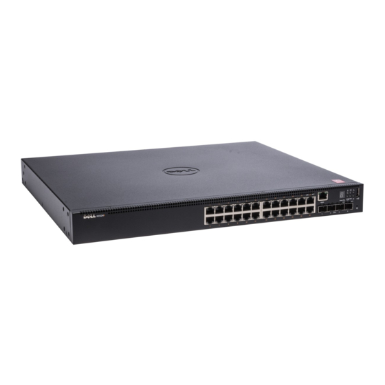
    440,0 x 257,0 x 43,5 mm (B x T x H). • 17,3 x 10,1 x 1,7 Zoll (B x T x H). Alle Dell-Netzwerke N1500 PoE-Modelle sind im Rack montierbare Switches mit 1 HE und folgenden Abmessungen: • 440,0 x 387,0 x 43,5 mm (B x T x H).
  • Seite 75 Netzteils (RPS-720) und der Lüfterwarnungen an. Abbildung 1-3. Dell-Netzwerke N1524P Nahansicht Die Frontblende der Dell-Netzwerke N1500P Serie, wie in Abbildung 1-3 dargestellt, verfügt in der ersten Reihe über Status-LEDs für den Überhitzungsalarm, die interne Stromversorgung und den Systemstatus.
  • Seite 76: Switch-Ports

    Die Frontblende des Dell-Netzwerke N1524/N1524P bietet 24 Gigabit- Ethernet (10BASE-T, 100BASE-TX, 1000BASE-T)-RJ-45-Ports mit Unterstützung für Auto-Negotiation für Geschwindigkeit, Datenflusssteuerung und Duplex. Die Dell-Netzwerke N1500 Serie Modelle unterstützen vier SFP+-10-Gbit-Ports. Dell-qualifizierte SFP+-Transceiver sind separat erhältlich. Die Frontblende des Dell-Netzwerke N1548/N1548P bietet 48 Gigabit- Ethernet (10BASE-T, 100BASE-TX, 1000BASE-T)-RJ-45-Ports mit Unterstützung für Auto-Negotiation für Geschwindigkeit, Datenflusssteuerung...
  • Seite 77: Konsolenport

    Konsolenport Der Dell-Netzwerke Konsolen-Port befindet sich auf der rechten Seite der Frontblende und wird durch ein -Symbol gekennzeichnet. Der Konsolen-Port ermöglicht eine serielle Kommunikation unter Verwendung des RS-232-Protokolls. Der serielle Port bietet eine direkte Verbindung zum Switch und erlaubt den Zugriff auf die Befehlszeilenschnittstelle (CLI) über ein Konsolenterminal, das wiederum über das mitgelieferte serielle Kabel...
  • Seite 78: Port- Und System-Leds

    Weitere Informationen über den Status der LEDs finden Sie im Benutzerkonfigurationshandbuch. Stack-Master-LED und Anzeige der Stack-Nummer Die Dell-Netzwerke Stack-Master-LED befindet sich auf der rechten Seite der Frontblende und wird durch ein -Symbol gekennzeichnet. Die Stack-Master-LED zeigt an, ob der Switch als Master-Einheit oder als Stack-Mitglied betrieben wird.
  • Seite 79: Dell-Netzwerke N1500 Serie Rückseite

    Lieferumfang enthalten) an den 14-poligen RPS-DC IN-Anschluss auf der Rückseite des Switches an. Dell-Netzwerke N1524P undN1548P Dell Networking N1524P und N1548P Switches verfügen über ein internes 600-Watt-Netzteil, mit dem bis zu 17 unterstützte Geräte bei voller PoE+- Stromversorgung (450 W) versorgt werden können. Für zusätzliche PoE+- Ports schließen Sie ein Dell-Netzwerke RPS1000 (nicht im Lieferumfang...
  • Seite 80: Belüftungssystem

    ANMERKUNG: Die PoE-Stromversorgung wird dynamisch zugewiesen. Nicht alle Ports erfordern die volle PoE+-Stromversorgung. Belüftungssystem Die N1500 Serie Switches werden von zwei festen internen Lüftern gekühlt. Dell-Netzwerke N1500 Serie Modellzusammenfassung Tabelle 1-2. N1500 Serie Modellzusammenfassung Marketing- Beschreibung Netzteil Muster- Muster- Modellname...
  • Seite 81: Dell-Netzwerke N1500 Serie

    Dell-Netzwerke N1500 Serie Installation Standortvorbereitung N1500 Serie Switches können in einem Standard-19-Zoll-Rack oder auf einer ebenen Fläche montiert werden. Stellen Sie sicher, dass am gewählten Ort der Installation die folgenden Voraussetzungen erfüllt sind: • Stromversorgung – Der Switch wird in der Nähe einer leicht zugänglichen Steckdose mit 100-240 V Wechselspannung und 50 bis 60 Hz installiert.
  • Seite 82: Auspacken Des N1500 Serie Switches

    Auspacken des N1500 Serie Switches Lieferumfang Kontrollieren Sie beim Auspacken der einzelnen Switches, ob jeweils die folgenden Teile vorhanden sind: • Ein Dell-Netzwerke Switch • Ein Kabel der Art RJ-45-an-DB-9 (weiblich) • Ein Rack-Montagekit: zwei Montagehalter, Schrauben und Käfigmuttern •...
  • Seite 83: Montieren Des N1500 Serie Switches In Ein Rack

    Montieren des N1500 Serie Switches in ein Rack WARNUNG: Sicherheits- und Lesen Sie die Sicherheitshinweise in den Betriebsbestimmungen sowie die Sicherheitshinweise für andere Switches, die mit dem Switch verbunden werden oder diesen unterstützen. Der Netzstromanschluss befindet sich auf der Rückseite des Switches. Installieren in einem Rack WARNUNG: Rack-Montagekits dürfen nicht dazu verwendet werden, den Switch...
  • Seite 84: Installieren Als Freistehender Switch

    4 Setzen Sie den Switch im 19-Zoll-Rack ein und stellen Sie sicher, dass die Rack-Montagelöcher am Switch mit den Bohrungen am Rack ausgerichtet sind. 5 Befestigen Sie den Switch am Rack mit den Rack-Schrauben oder mit Käfigmuttern und den entsprechenden Schrauben mit Unterlegscheiben (je nach Rack).
  • Seite 85: Stacking Mehrerer Switches

    Stacking mehrerer Switches Es ist möglich, mithilfe der SFP+-Ports bis zu vier N1500 Serie Switches zu stapeln. ANMERKUNG: N1500 Serie Switches können nur mit anderen N15xx Serie- Switches gestapelt werden. Stapeln Sie keine N1500 Serie Switches mit N2000, N3000 oder N4000 Serie-Switches. Wenn mehrere Switches über die Stack-Ports verbunden sind, arbeiten sie als eine einzige Einheit mit bis zu 192 RJ-45-Ports an der Frontblende.
  • Seite 86 4 Schalten Sie einen Switch ein und warten Sie, bis er vollständig hochgefahren ist (1-2 Minuten), bevor Sie fortfahren. Schalten Sie dann die angeschlossenen Switches der Reihe nach ein, beginnend mit dem Switch, der direkt mit dem zuletzt eingeschalteten Switch verbunden ist und warten Sie, bis der Switch vollständig hochgefahren ist, bevor Sie den nächsten Switch einschalten.
  • Seite 87 Stacking-Standby Die Stacking-Funktion unterstützt eine Standby- oder Backup-Einheit, die die Rolle der Master-Einheit übernimmt, falls die Master-Einheit im Stack ausfällt. Sobald der Ausfall der Master-Einheit im Stack erkannt wurde, aktiviert die Standby-Einheit die Steuerungsebene auf der neuen Master- Einheit und synchronisiert alle anderen Stack-Einheiten mit der aktuellen Konfiguration.
  • Seite 88: Starten Und Konfigurieren Des Dell-Netzwerke N1500 Serie Switches

    Starten und Konfigurieren des Dell- Netzwerke N1500 Serie Switches Das folgende Flussdiagramm enthält eine Übersicht über die erforderlichen Schritte für die Erstkonfiguration, nachdem der Switch entpackt und montiert wurde. Flussdiagramm für Installation und Konfiguration Abbildung 1-8. Handbuch zum Einstieg...
  • Seite 89: Verbinden Eines N1500 Serie Switches Mit Einem Terminal

    Nachdem Sie alle externen Verbindungen hergestellt haben, schließen Sie ein serielles Terminal an, um den Switch zu konfigurieren. ANMERKUNG: Lesen Sie die Versionshinweise für dieses Produkt, bevor Sie fortfahren. Sie können die Versionshinweise von der Dell Support-Website unter dell.com/support herunterladen. ANMERKUNG: Es wird empfohlen, die aktuelle Version der Benutzerdokumentation von der Dell Support-Website unter dell.com/support herunterzuladen.
  • Seite 90 3 Schließen Sie den RJ-45-Anschluss des Kabels direkt an den Switch- Konsolen-Port an. Der Dell-Netzwerke Konsolen-Port befindet sich auf der rechten Seite der Frontblende und ist mit einem | O|O |-Symbol gekennzeichnet, wie in Abbildung 1-9 auf Seite 90 dargestellt.
  • Seite 91: Anschließen Eines Switches An Eine Stromquelle

    2 Schließen Sie das Stromkabel (ein 1,5 m langes Standard-Netzkabel mit Schutzleiter) an die Netzbuchse an der Rückseite an (siehe Abbildung 1-10 auf Seite 92). Für die Dell-Netzwerke N1500P Serie-Modelle ist ein eingekerbtes C15-zu-NEMA 5-15P-Stromkabel erforderlich (separat erhältlich).
  • Seite 92: Starten Des Switches

    Abbildung 1-10. Wechselstrom- und Gleichstromanschluss ein einen N1548 Switch An Gleichstromquelle (Optional) An Netzstromquelle Starten des Switches Wenn die Stromversorgung eingeschaltet wird und das lokale Terminal bereits angeschlossen ist, führt der Switch den Einschaltselbsttest (Power-On Self-Test (POST)) aus. Der Einschaltselbsttest wird bei jeder Initialisierung des Switches durchlaufen;...
  • Seite 93: Durchführung Der Erstkonfiguration

    Remote-Verwaltung des Switches über ein Verbindung über Telnet (Telnet -Client) oder HTTP (Web-Browser) zuzulassen. Aktivieren der Remote-Verwaltung Verwenden Sie auf den Dell-Netzwerke N1500 Serie Switches für die In- Band-Verwaltung einen der Switch-Ports auf der Frontblende. Standardmäßig sind alle Switch-Ports Mitglieder von VLAN 1.
  • Seite 94: Durchführen Der Erstkonfiguration

    Startkonfiguration zurück, um den Dell Easy Setup-Assistent erneut ausführen zu können. Weitere Informationen über Erstkonfiguration mithilfe der Befehlszeilenschnittstelle finden Sie im CLI-Referenzhandbuch. Dieses Handbuch zum Einstieg zeigt, wie Sie den Dell Easy Setup-Assistent für die Erstkonfiguration des Switches einsetzen. Der Assistent konfiguriert den Switch wie folgt: •...
  • Seite 95: Beispielsitzung

    Beispielsitzung Dieser Abschnitt beschreibt eine Dell Easy Setup-Assistent Sitzung. In dieser Beispielsitzung werden folgende Werte verwendet: • Die zu verwendend SNMP-Communityzeichenfolge ist public. • Die NMS (Network Management System)-IP-Adresse lautet 10.1.2.100. • Der Benutzername lautet admin, und das Kennwort ist admin123.
  • Seite 96: Dell Easy Setup-Assistentenkonsole (Beispiel)

    Dell Easy Setup-Assistentenkonsole (Beispiel) Das folgende Beispiel enthält eine Abfolge von Eingabeaufforderungen und Reaktionen im Rahmen einer Beispielsitzung des Dell Easy Setup-Assistent, wobei die oben genannten Eingabewerte verwendet werden. Nachdem der Switch den Einschaltselbsttest abgeschlossen hat und gestartet wurde, wird das folgende Dialogfeld angezeigt: Unit 1 - Waiting to select management unit)>...
  • Seite 97 [Privilege Level 15] to this account. You can use Dell Network Manager or other management interfaces to change this setting, and to add additional management system information later. For more information on adding management systems, see the user documentation.
  • Seite 98 If the information is incorrect, enter (N) to discard the configuration and restart the wizard: [Y/N] y Thank you for using the Dell Easy Setup Wizard. You will now enter CLI mode. Applying Interface configuration, please wait...
  • Seite 99: Nächste Schritte

    • Geben Sie für die VLAN-1-Routing-Schnittstelle show ip interface vlan 1 ein. Zum Zugriff auf die Dell OpenManage Switch Administrator-Schnittstelle, geben Sie die IP-Adresse der VLAN-1-Verwaltungsschnittstelle in das Adressfeld eines Webbrowsers ein. Für einen Remote-Verwaltungszugriff auf die Befehlszeilenschnittstelle geben Sie die IP-Adresse der VLAN-1- Verwaltungsschnittstelle in einen Telnet- oder SSH-Client ein.
  • Seite 100: Nom-Informationen (Nur Mexiko)

    Einzelheiten Exporteur: Dell Inc. One Dell Way Round Rock, TX 78682 Importeur: Dell Computer de México, S.A. de C.V. Paseo de la Reforma 2620 - 11 Piso Col. Lomas Altas 11950 México, D.F. Frachtanschrift: Dell Computer de México, S.A. de C.V.
  • Seite 101 (fortgesetzt) Tabelle 1-3. NOM-Informationen Erforderliche Informationen Einzelheiten N1548P: • 110-V-Stromkreis: ~ 5,23 A • 220-V-Stromkreis: ~ 2,76 A ANMERKUNG: Die hier angegebenen Werte beziehen sich auf den Verbrauch eines einzelnen Netzteils. Handbuch zum Einstieg...
  • Seite 102 Dell Networking Коммутатор серии N1500 руководство по началу работы Нормативные номера моделей: N1524, N1524P, N1548, N1548P...
  • Seite 103 повреждения оборудования, получения легких травм или угрозу для жизни. ____________________ Авторское право © 2015 Dell Inc. Все права защищены. Данный продукт защищен законами США об авторских правах и интеллектуальной собственности, а также аналогичными международными законами. Dell™ и логотип Dell являются товарными знаками Dell Inc.в Соединенных Штатах и/или иных...
  • Seite 104 Индикатор мастера стека и отображение номера стека ....Задняя панель Dell Networking Cерия N1500 . . . Источники питания ....
  • Seite 105 ..Создание стека коммутаторов ..5 Запуск и настройка коммутатора Dell Networking Cерия N1500 ... Подключение коммутатора Cерия N1500 к...
  • Seite 106: Введение

    серии N1500, в том числе сведения о его установке и первоначальной настройке. Дополнительную информацию о настройке и отслеживании функций коммутатора см. в Руководстве пользователя по настройке, доступное на сайте поддержки Dell dell.com/support, предоставляющем информацию о последних обновлениях документации и микропрограммного обеспечения.
  • Seite 107: Обзор Аппаратного Обеспечения

    17,3 x 10,1 x 1,7 дюйма (Ш x Г x В) • Все модели Dell Networking N1500 с технологией PoE являются коммутаторами 1U, монтируемыми в стойку, со следующими габаритными размерами: 440,0 x 387,0 x 43,5 мм (Ш x Г x В) •...
  • Seite 108 Рисунок 1-2. Dell Networking N1524 (крупным планом) На передней панели коммутатора Dell Networking Cерия N1500, показанной на Рис. 1-2, в верхнем ряду находятся индикаторы состояния сигналов тревоги превышения температуры, внутреннего питания и работоспособности системы. Нижний ряд светодиодных индикаторов состояния отображает состояние мастера...
  • Seite 109: Порты Коммутатора

    Рисунок 1-3. Dell Networking N1524P (крупным планом) На передней панели Dell Networking серии N1500P, показанной на Рис. 1-3, в верхнем ряду находятся индикаторы состояния сигналов тревоги превышения температуры, внутреннего питания и работоспособности системы. Нижний ряд светодиодных индикаторов состояния отображает состояние мастера стека, модульного...
  • Seite 110: Консольный Порт

    Значения по умолчанию: скорость передачи данных 9600 бод, 8 бит данных, без контроля четности, 1 стоповый бит, без управления потоком. Порт USB Порт USB Dell Networking расположен в правой части передней панели и помечен символом . Женский порт USB типа А поддерживает диски флэш-памяти, совместимые...
  • Seite 111: Кнопка Reset (Сброс)

    Кнопка Reset (Сброс) Кнопка Reset (Сброс) Dell Networking расположена в правой части передней панели и помечена символом . Доступ к кнопке Reset (Сброс), позволяющей выполнять аппаратный сброс на коммутаторе, осуществляется через отверстие. Чтобы использовать кнопку Reset (Сброс), вставьте в отверстие разогнутую...
  • Seite 112: Задняя Панель Dell Networking Cерия N1500

    Коммутатор N1524 имеет внутренний источник питания 40 Вт. N1548 имеет внутренний источник питания 100 Вт. При необходимости резервного питания соедините Dell Networking RPS720 (не входит в комплект) с 14-контактным разъемом RPS DC IN на задней панели коммутатора. Dell Networking N1524P и N1548P Коммутаторы...
  • Seite 113: Система Вентиляции

    ПРИМЕЧАНИЕ: Мощность PoE распределяется динамически. Не все порты требуют полной мощности PoE+. Система вентиляции Два фиксированных внутренних вентилятора охлаждают коммутаторы Cерия N1500. Краткий обзор модели Dell Networking Cерия N1500 Таблица 1-2. Краткий обзор модели Cерия N1500 Маркетинговое Описание Блок Нормативный...
  • Seite 114: Установка Dell Networking Cерия N1500

    Установка Dell Networking Cерия N1500 Подготовка места Коммутаторы Cерия N1500 можно монтировать в стандартную стойку 48,26 см (19 дюймов) или размещать на ровной поверхности. Убедитесь, что выбранное место для установки соответствует следующим требованиям. Питание: коммутатор установлен рядом с легко доступной розеткой 100–240 В...
  • Seite 115: Распаковка Коммутатора Cерия N1500

    Распаковка коммутатора Cерия N1500 Комплект поставки При распаковке коммутатора убедитесь, что в комплект включены следующие предметы: один коммутатор Dell Networking; • один женский кабель RJ-45—DB-9; • один комплект стойки (два монтажных кронштейна, болты и гайки); • один набор самоклеящихся резиновых ножек для автономного...
  • Seite 116: Установка Коммутатора Cерия N1500 В Стойку

    Установка коммутатора Cерия N1500 в стойку ПРЕДУПРЕЖДЕНИЕ! Прочтите информацию по технике безопасности в документации по безопасности и соответствию нормативным требованиям, а также информацию по технике безопасности для других коммутаторов, подключаемых к данному коммутатору или поддерживающих его. Разъем питания переменного тока располагается на задней панели коммутатора. Монтаж...
  • Seite 117: Установка В Качестве Автономного Коммутатора

    3 Повторите действия для кронштейна для монтажа в стойку с другой стороны устройства. 4 Установите устройство в стойку на 48,26 см (19 дюймов), убедившись в том, что монтажные отверстия в устройстве совпадают с монтажными отверстиями в стойке. 5 Закрепите коммутатор в стойке при помощи болтов для монтажа в стойку или кузовных...
  • Seite 118: Стекирование Нескольких Коммутаторов

    Стекирование нескольких коммутаторов Возможно осуществлять стекирование до четырех коммутаторов Cерия N1500 с помощью портов SFP+. ПРИМЕЧАНИЕ: Коммутаторы Cерия N1500 поддерживают стекирование только с другими коммутаторами серии N15xx. Не осуществляйте стекирование коммутаторов Cерия N1500 с коммутаторами серии N2000, N3000 или N4000. Когда...
  • Seite 119 4 Прежде чем продолжить, включите питание на одном коммутаторе и подождите до его полной загрузки (1–2 минуты). Затем по очереди включите питание на каждом из соединеннных коммутаторов, начиная с того, который непосредственно соединен с последним включенным коммутатором, и подождите до полной загрузки каждого из них перед включением следующего...
  • Seite 120 Режим ожидания стекинга Функция стекирования поддерживает устройство режима ожидания или резервного копирования, перенимающее роль главного устройства в случае отказа главного устройства в стеке. После того как обнаружен сбой главного устройства в стеке, устройство режима ожидания включает уровень управления на новом главном...
  • Seite 121: Запуск И Настройка Коммутатора Dell

    Запуск и настройка коммутатора Dell Networking Cерия N1500 Следующая блок-схема содержит обзор действий, которые необходимо выполнить для первоначальной настройки, после того как коммутатор распакован и закреплен. Установка и настройка блок-схемы Рисунок 1-8. Руководство по началу работы...
  • Seite 122: Подключение Коммутатора Cерия N1500 К Терминалу

    ПРИМЕЧАНИЕ: Ознакомьтесь с примечаниями к версии данного изделия, прежде чем продолжить установку. Примечания к версии можно загрузить с сайта технической поддержки Dell по адресу dell.com/support. ПРИМЕЧАНИЕ: Мы рекомендуем получить последнюю версию документации пользователя на сайте технической поддержки Dell по адресу...
  • Seite 123 клавиши CTRL. Убедитесь, что установлены параметры для клавиш терминала (не для клавиш Microsoft Windows). 3 Соедините разъем RJ-45 через кабель непосредственно с консольным портом коммутатора. Консольный порт Dell Networking расположен в правой части передней панели и помечен символом |O|O|, как показано на Рис. 1-9 на стр. 123.
  • Seite 124: Подключение Коммутатора К Источнику Питания

    2 Подключите стандартный кабель питания 1,5 м (5 футов) с защитным заземлением к главному разъему питания переменного тока, расположенному на задней панели (см. Рис. 1-10 на стр. 125). Модели Dell Networking серии N1500P требуют кабель питания C15—NEMA 5-15P (приобретается отдельно).
  • Seite 125: Загрузка Коммутатора

    Рисунок 1-10. Подключение коммутатора N1548 к сети переменного и постоянного тока Источник питания постоянного тока (дополнительно) Источник питания переменного тока Загрузка коммутатора При включении питания с уже подключенным локальным терминалом коммутатор подвергается самотестированию при включении питания (POST). POST запускается каждый раз при инициализации коммутатора и проверяет наличие компонентов...
  • Seite 126: Выполнение Первоначальной Настройки

    разрешения удаленного управления коммутатором через Telnet (клиент Telnet) или HTTP (веб-браузер). Включение удаленного управления На коммутаторах Dell Networking Cерия N1500 используйте любой из портов на передней панели коммутатора для внутриполосного управления. Все порты коммутатора по умолчанию являются членами сети VLAN 1.
  • Seite 127: Процедура Первоначальной Настройки

    момент, нажав клавиши CTRL+Z, но все настройки будут сброшены, и коммутатор будет использовать значения по умолчанию. ПРИМЕЧАНИЕ: Если вы не запустите Мастер простой установки Dell или не ответите на первоначальный вопрос мастера простой установки в течение 60 секунд, коммутатор перейдет в режим интерфейса командной строки.
  • Seite 128: Пример Сеанса

    Пример сеанса В этом разделе описывается сеанс Мастер простой установки Dell. В примере сеанса используются следующие значения. Строка сообщества SNMP, которая будет использоваться: public. • IP-адрес системы сетевого управления (NMS): 10.1.2.100. • Имя пользователя: admin. Пароль: admin123. • IP-адрес для интерфейса маршрутизации VLAN 1: 10.1.1.200. Маска подсети: •...
  • Seite 129 60 seconds)? [Y/N] y Step 1: The system is not set up for SNMP management by default. To manage the switch using SNMP (required for Dell Network Manager) you can Set up the initial SNMP version 2 account now.
  • Seite 130 ПРИМЕЧАНИЕ: Если настройка осуществлена, уровень доступа по умолчанию установлен на максимально возможный доступ для интерфейса управления SNMP. Изначально будет активирован только SNMPv2. SNMPv3 отключен до тех пор, пока вы не настроите защищенный доступ для SNMPv3 (например, идентификатор подсистемы, вид и т. д.). Please enter the IP address of the Management System (A.B.C.D) or wildcard (0.0.0.0) to manage from any Management Station.
  • Seite 131 If the information is incorrect, enter (N) to discard the configuration and restart the wizard: [Y/N] y Thank you for using the Dell Easy Setup Wizard. You will now enter CLI mode. Applying Interface configuration, please wait... Руководство по началу работы...
  • Seite 132: Дальнейшие Действия

    Для интерфейса маршрутизации сети VLAN 1 введите команду show ip • interface vlan 1. Чтобы получить доступ к интерфейсу Dell OpenManage Switch Administrator, введите IP-адрес интерфейса управления VLAN 1 в поле адреса веб-браузера. Для удаленного доступа к управлению интерфейсом командной строки введите IP- адрес...
  • Seite 133 Подробности Экспортер: Dell Inc. One Dell Way Round Rock, TX 78682 Импортер: Dell Computer de México, S.A. de C.V. Paseo de la Reforma 2620 - 11 Piso Col. Lomas Altas 11950 México, D.F. Доставка по адресу: Dell Computer de México, S.A. de C.V.
  • Seite 134 Таблица 1-3. Сведения о мексиканских стандартах (NOM) (продолжение) Необходимые сведения Подробности N1548: • 110 В: 0,42 A • 220 В: 0,4 A N1548P: • 110 В: ~5,23 A • 220 В: ~2,76 A ПРИМЕЧАНИЕ: Текущие значения указаны для одного источника питания. Руководство...
  • Seite 135 Dell Networking N1500 Serijski prekidač Priručnik za početak rada Regulativni modeli: N1524, N1524P, N1548, N1548P...
  • Seite 136 Dell™ i logo kompanije Dell su zaštitni znakovi Dell Inc. u SAD i/ili u drugim jurisdikcijama. Svi drugi znaci i nazivi spomenuti ovde mogu da budu zaštitni znakovi kompanija koje su njihovi vlasnici.
  • Seite 137 . . . LED glavnog steka i prikaz broja steka . . . Dell Networking N1500 serija Zadnja ploča . . . Napajanje ....
  • Seite 138 ..Primer sesije ....Primer konzole Dell čarobnjaka za jednostavno podešavanje ..
  • Seite 139: Uvod

    Informacije o tome kako se vrši konfiguracija i kako se prate funkcije prekidača potražite u Korisničkom vodiču za konfiguraciju, koji se nalazi na Dell internet stranici za podršku dell.com/support, gde se nalaze najnovije verzije dokumenata i firmvera. Ovaj dokument ima sledeće odeljke: Dell Networking N1500 serija Opis •...
  • Seite 140: Opis Hardvera

    U ovom delu nalaze se informacije o karakteristikama uređaja i modularnim hardverskim konfiguracijama Dell Networking N1500 serijskih prekidača. Svi Dell Networking N1500 modeli koji nisu PoE su 1U prekidači koji mogu da se montiraju u ormare, sa sledećim fizičkimdimenzijama: 440,0 x 257,0 x 43,5 mm (Š x D x V).
  • Seite 141 Slika1-2. Dell Networking N1524 Detaljan prikaz Prednja Dell Networking N1500 serija ploča prekidača, prikazana u Slika 1-2, ima statusne LED lampice za alarm pregrevanja, unutrašnje napajanje i status stanja sistema u traci na vrhu. Traka na dnu statusnih LED lampica prikazuje glavni stek, status dodatnog napajanja (RPS 720) i status alarma ventilatora.
  • Seite 142: Portovi Prekidača

    Portovi prekidača Na Dell Networking N1524/N1524P prednjoj ploči nalaze se 24 Gigabit Ethernet (10BASE-T, 100BASE-TX, 1000BASE-T) RJ-45 portovi koji podržavaju automatsko podešavanje brzine, kontrole protoka i dupleksa. Modeli Dell Networking N1500 serija podržavaju četiri SFP+ 10G portove. Dell SFP+ primopredajnici prodaju se posebno.
  • Seite 143: Konzolni Port

    CLI Dell podržava samo promenu brzine. Podrazumevana je brzina od 9600 boda, 8 data bitova, bez pariteta, 1 dtop bit, bez kontrole protoka. USB port USB Dell Networking port nalazi se u desnom delu prednje ploče i obeležen je simbolom . Tip-A, ženski USB port podržava fleš memoriju predviđenu za USB 2.0.
  • Seite 144: Sistemske Led Lampice I Lampice Portova

    Dodatne informacije o statusu koji pokazuju LED lampice potražite u Korisničkom vodiču za konfiguraciju. LED glavnog steka i prikaz broja steka LED Dell Networking glavnog steka nalazi se u desnom delu prednje ploče i obeležen je simbolom . LED glavnog steka pokazuje da li prekidač radi kao glavna jedinica ili kao modul (jedinica u nizu).
  • Seite 145: Dell Networking N1500 Serija Zadnja Ploča

    Dell Networking N1500 serija Zadnja ploča Na sledećim slikama prikazane su zadnje ploče Dell Networking N1500 i N1500P serijski prekidači. Slika1-4. N1500 serija Zadnja ploča Utičnica za naizmeničnu struju Ventilacioni otvori Slika1-5. N1524P/N1548P Zadnja ploča Napajanje OPREZ: Iskopčajte kabl iz izvora napajanja pre nego što uklonite modul za napajanje.
  • Seite 146: Ventilacioni Sistem

    Ventilacioni sistem Dva fiksna unutrašnja ventilatora hlade N1500 serija prekidače. Dell Networking N1500 serija Rezime modela Tabela 1-2. N1500 serija Rezime modela Ime modela za Opis Jedinica za Regulatorni Regulatorni marketinške napajanje broj modela broj tipa svrhe Dell Networking 24x1G/4x10G SFP+...
  • Seite 147: Dell Networking N1500 Serija Instalacija

    Dell Networking N1500 serija Instalacija Priprema lokacije N1500 serija prekidači mogu da se postave u standardni ormar veličine 48,26 cm (19 inča) ili da se stave na ravnu površinu. Vodite računa da izabrana lokacija gde se vrši instalacija ispunjava sledeće uslove: Napajanje —...
  • Seite 148: Otpakivanje N1500 Serija Prekidača

    Otpakivanje N1500 serija prekidača Sadržaj paketa Prilikom otpakivanja svakog prekidača, proverite da li paket sadrži sledeće stavke: Jedan prekidač Dell Networking • Jedan ženski kabl od RJ-45 do DB-9 • Jedan komplet za montažu u ormaru: dva nosača, zavrtnji i cilindrične navrtke •...
  • Seite 149: Montaža Prekidača N1500 Serija U Ormar

    Montaža prekidača N1500 serija u ormar UPOZORENJE: Pročitajte bezbednosne informacije u Bezbednosne i regulatorne informacije kao i bezbednosne informacije za druge prekidače koje se priključuju u prekidač ili koji služe za njegovu podršku. Priključak za napajanje naizmeničnom strujom nalazi se na zadnjoj ploči prekidača. Montaža u ormar UPOZORENJE: Nemojte koristiti komplete za montažu u ormar za...
  • Seite 150: Montaža Samostalnog Prekidača

    4 Umetnite prekidač u ormar od 48,26 cm (19 inča), vodeći računa da se otvori za montažu na prekidaču podudaraju sa otvorima na nosaču. 5 Prekidač pričvrstite za ormar ili pomoću zavrtanja za ormar ili pomoću cilindričnih navrtki i osigurajte zavrtnje podloškama (zavisno od vrste ormara koji imate).
  • Seite 151: Slaganje Više Prekidača

    Slaganje više prekidača Moguće je složiti najviše četiri N1500 serija prekidača preko SFP+ portova. NAPOMENA: N1500 serija prekidači podržavaju samo slaganje sa prekidačima iz drugih N15xx serija. Nemojte slagati N1500 serija prekidače sa prekidačima iz N2000, N3000 ili N4000 serije. Kada se poveže više prekidača preko portova za stekove, oni rade kao jedna jedinica sa maksimalno 192 RJ-45 porta na prednjoj ploči.
  • Seite 152 Slika1-7. Jedinica 1 Jedinica 2 Jedinica 3 Stek u Slika 1-7 povezan je u obliku prstena i ima sledeće fizičke veze između prekidača: Levi SFP+ port Te1/0/1 na Jedinici 1 (gornja) povezan je sa desnim SFP+ • port Te2/0/2 na Jedinici 2. Levi SFP+ port Te2/0/1 na Jedinici 2 (gornja) povezan je sa desnim SFP+ •...
  • Seite 153 Pomoćna jedinica steka Stek podržava Pomoćnu jedinicu ili rezervnu jedinicu koja preuzima ulogu glavne jedinice ako glavna jedinica u steku bude u kvaru. Čim se utvrdi kvar glavne jedinice u steku, Pomoćna jedinica omogućava upravljanje preko nove glavne jedinice i vrši sinhronizaciju svih ostalih jedinica u steku na trenutnu konfiguraciju.
  • Seite 154: Pokretanje I Konfigurisanje

    Pokretanje i konfigurisanje Dell Networking N1500 serija prekidača Sledeći dijagram toka prikazuje korake koje pravite da biste izvršili početnu konfiguraciju nakon raspakovanja i montaže prekidača. Dijagram toka instalacije i konfiguracije Slika1-8. Priručnik za početak rada...
  • Seite 155: Priključivanje N1500 Serija Prekidača U Terminal

    Kada izvršite sva spoljna povezivanja, priključite serijski terminal u prekidač da izvršite konfiguraciju prekidača. NAPOMENA: Pročitajte Napomene uz izdanje za ovaj proizvod pre nego što nastavite. Možete preuzeti Napomene uz izdanje sa Dell internet stranice za podršku na dell.com/support. NAPOMENA: Preporučujemo da nabavite najnoviju verziju dokumentacije za korisnike sa Dell internet stranice za podršku na...
  • Seite 156 Microsoft Windows). 3 Priključite konektor RJ-45 na kablu direktno u konzolni port na prekidaču. Dell Networking konzolni port se nalazi u desnom delu prednje ploče i označen je simbolom |O|O|, kako je prikazano na Slika 1-9 na page 156.
  • Seite 157: Priključivanje Prekidača U Napajanje

    2 Pomoću standardnog kabla od 1,5 m (5 stopa) sa uzemljenjem, povežite kabl za napajanje u utičnicu za naizmeničnu struju koja se nalazi na zadnjoj ploči (pogledajte Slika 1-10 na page 158). Modeli serije Dell Networking N1500P zahtevaju kabl za napajanje sa zarezom od C15 do NEMA 5-15P (kupuje se posebno).
  • Seite 158: Pokretanje Prekidača

    Slika1-10. Priključivanje jednosmerne i naizmenične struje u prekidač N1548 U izvor napajanja jednosmernom strujom (opciono) U izvor napajanja naizmeničnom strujom Pokretanje prekidača Ako se uključi napajanje kada je lokalni terminal već priključen, prekidač prolazi kroz automatsko testiranje napajanja (POST). POST se pokreće svaki put kada se ključi prekidač...
  • Seite 159: Početna Konfiguracija

    Prekidač Dell Networking nema sačuvanu konfiguraciju. • Prekidač Dell Networking se uspešno pokrenuo. • Veza sa konzolom je uspostavljena i pojavljuje se upit Dell Čarobnjaka za • jednostavno podešavanje na ekranu ekvivalenta terminala VT100. Početna konfiguracija prekidača vrši se preko konzolnog porta. Nakon početne konfiguracije možete upravljate prekidačem sa već...
  • Seite 160: Procedura Početne Konfiguracije

    Čarobnjaka za jednostavno početno podešavanje u roku od 60 sekundi, prekidač ulazi u CLI režim. Resetujte prekidač sa praznom početnom konfiguracijom da biste vratili Dell Čarobnjaka za jednostavno podešavanje. Dodatne informacije o vršenju početne konfiguracije pomoću CLI, pogledajte Vodič...
  • Seite 161: Primer Sesije

    Primer sesije Ovaj odeljak opisuje Dell Čarobnjaka za jednostavno podešavanje sesiju. U primeru sesije korišćene su sledeće vrednosti: SNMP niska zajednice koja će se koristiti je public. • IP adresa sistema za upravljanje mrežom (NMS) je 10.1.2.100. • Korisničko ime je admin, a lozinka admin123.
  • Seite 162: Primer Konzole Dell Čarobnjaka Za Jednostavno Podešavanje

    Primer konzole Dell čarobnjaka za jednostavno podešavanje Sledeći primer sadrži niz upita i odgovora povezanih sa pokretanjem primera sesije Dell Čarobnjaka za jednostavno podešavanje koristeći vrednosti unosa navedene ispod. Kada se završi POST na prekidaču, i kada se prekidač pokrene, pojavljuje se sledeći dijalog:...
  • Seite 163 [Privilege Level 15] to this account. You can use Dell Network Manager or other management interfaces to change this setting, and to add additional management system information later. For more information on adding management systems, see the user documentation.
  • Seite 164 If the information is incorrect, enter (N) to discard the configuration and restart the wizard: [Y/N] y Thank you for using the Dell Easy Setup Wizard. You will now enter CLI mode. Priručnik za početak rada...
  • Seite 165: Sledeći Koraci

    Za interfejs za usmeravanje VLAN 1, unesite show ip interface vlan 1. • Za pristup Dell OpenManage interfejsu administratora prekidača, unesite IP adresu VLAN 1 upravljačkog interfejsa u polje za adresu veb pregledača. Za pristup daljinskog upravljanja CLI, unesite IP adresu VLAN 1 upravljačkog interfejsa u Telnet ili SSH klijent.
  • Seite 166: Nom Informacije

    Detalji Izvoznik: Dell Inc. One Dell Way Round Rock, TX 78682 Uvoznik: Dell Inc. de México, S.A. de C.V Paseo de la Reforma 2620 - 11 Piso Col. Lomas Altas 11950 México, D.F. Slati u: Dell Inc. de México, S.A. de C.V al Cuidado de Kuehne &...
  • Seite 167 Tabela 1-3. NOM informacije (nastavljeno) Potrebne informacije Detalji N1548P: • 110V struja: ~5,23A • 220V struja: ~2,76A NAPOMENA: Vrednosti struje prikazane ovde odnose se na potrošnju jedne jedinice. Priručnik za početak rada...
  • Seite 168: Guía De Introducción

    Dell Networking Conmutador N1500 Series Guía de introducción Modelos normativos: N1524, N1524P, N1548, N1548P...
  • Seite 169 Copyright© 2015 Dell, Inc. Todos los derechos reservados. Este producto está protegida por las leyes de propiedad intelectual y de copyright internacionales y de EE. UU. Dell™ y el logotipo de Dell son marcas comerciales de Dell Inc. en los Estados Unidos y/o en otras jurisdicciones. El resto de marcas y nombres que se mencionan en este documento pueden ser marcas comerciales de sus respectivas compañías.
  • Seite 170 ....Descripción general del hardware ..Panel frontal de Dell Networking N1500 Series . . . Puertos del conmutador ... . .
  • Seite 171 . . . Sesión de ejemplo ....Ejemplo de consola Dell Easy Setup Wizard . . . Próximos pasos: ....
  • Seite 172: Introducción

    Para la infraestructura crítica, se recomienda realizar una presentación previa de la nueva versión en una parte que no sea crítica de la red con el fin de verificar la configuración y el funcionamiento de la red con la nueva versión del SO de Dell. Dell Networking N1500 Series Descripción general...
  • Seite 173: Descripción General Del Hardware

    Esta sección contiene información sobre las características de los dispositivos y las configuraciones de hardware modulares para los conmutadores Dell Networking N1500 Series. Todos los modelos Dell Networking N1500 que no son PoE son conmutadores montables en rack de 1U con las dimensiones físicas siguientes: •...
  • Seite 174 (RPS 720) y el estado de la alarma del ventilador. Ilustración 1-3. Primer plano de Dell Networking N1524P El panel frontal del Dell Networking N1500P Series, según se muestra en la Ilustración 1-3, tiene indicadores LED del estado de la alarma de exceso de temperatura y el estado de la alimentación interna y la condición del sistema en la fila...
  • Seite 175: Puertos Del Conmutador

    RJ-45 Gigabit Ethernet (10BASE-T, 100BASE-TX y 1000BASE-T que admiten la negociación automática de velocidad, control de flujo y modo dúplex. Los modelos Dell Networking N1500 Series admiten cuatro puertos 10G SFP +. Los transceptores SFP+ homologados por Dell se venden por separado.
  • Seite 176: Puerto De Consola

    9600 baudios, 8 bits de datos, sin paridad, 1 bit de parada, sin control de flujo. Puerto USB El puerto USB de Dell Networking está ubicado en el lado derecho del panel frontal y está etiquetado con un símbolo . El puerto USB hembra de tipo A admite unidades de memoria flash compatibles con USB 2.0.
  • Seite 177: Indicadores Led Del Puerto Y Del Sistema

    LED de unidad maestra de la pila y pantalla de número de pila El LED de la unidad maestra de la pila del Dell Networking se encuentra en el lado derecho del panel frontal y está etiquetado con un símbolo .
  • Seite 178: Panel Posterior De Dell Networking N1500 Series

    600 vatios que alimenta hasta 17 en dispositivos con una potencia completa PoE+ (450 W). Para disponer de más puertos PoE+, conecte un Dell Networking MPS1000 (no se incluye) al conector MPS DC IN de 16 patas de la parte posterior del conmutador.
  • Seite 179: Sistema De Ventilación

    Sistema de ventilación Dos ventiladores internos fijos sirven para enfriar los conmutadores N1500 Series. Resumen del modelo Dell Networking N1500 Series Tabla 1-2. N1500 Series Resumen del modelo Nombre del Descripción Unidad de Número de Número modelo de fuente de...
  • Seite 180: Instalación De Dell Networking N1500 Series

    Instalación de Dell Networking N1500 Series Preparación del sitio Los conmutadores N1500 Series se pueden montar en un rack estándar de 48,26 cm (19 pulgadas) o se pueden colocar sobre una superficie plana. Asegúrese de que la ubicación elegida para la instalación cumpla con los requisitos siguientes: •...
  • Seite 181: Desembalaje Del Conmutador N1500 Series

    Contenido del paquete Al desembalar cada conmutador, asegúrese de que los siguientes elementos están incluidos: • Un conmutador Dell Networking • Un cable hembra URJ-45 a DB-9 • Un kit de montaje: dos soportes de montaje, pernos y tuercas prisioneras •...
  • Seite 182: Montaje Del Conmutador N1500 Series En El Rack

    Montaje del conmutador N1500 Series en el rack ADVERTENCIA: Información Lea la información de seguridad del documento reglamentaria y de seguridad , así como la información de seguridad de los otros conmutadores que están conectados o asociados al conmutador. El conector de alimentación de CA se encuentra en el panel posterior del conmutador.
  • Seite 183: Instalación Como Conmutador Independiente

    4 Inserte el conmutador en el rack de 48,26 cm (19 pulgadas) y asegúrese de que los orificios de montaje en rack del conmutador coinciden con los orificios de montaje del rack. 5 Fije el conmutador en el rack con los pernos o bien con las tuercas prisioneras, sus pernos y arandelas (según el tipo de rack del que disponga).
  • Seite 184: Apilamiento De Varios Conmutadores

    Apilamiento de varios conmutadores Se pueden apilar hasta cuatro conmutadores N1500 Series mediante los puertos SFP+. NOTA: Los conmutadores N1500 Series solo se pueden apilar con otros conmutadores de la serie N15xx. No apile conmutadores N1500 Series con conmutadores de las series N2000, N3000 o N4000. Cuando hay varios conmutadores conectados utilizando los puertos de pila, todos funcionan como una unidad única con hasta 192 puertos RJ-45 del panel frontal.
  • Seite 185 4 Encienda un conmutador y deje que arranque completamente (de 1 a 2 minutos) antes de continuar. A continuación encienda cada uno de los conmutadores conectados en secuencia, comenzando con el conmutador conectado directamente al conmutador más reciente y deje que cada conmutador se inicie completamente antes de encender el próximo.
  • Seite 186 Reserva de apilamiento La función de apilamiento admite una unidad de reserva o de copia de seguridad que asume la función de la unidad principal en caso de que la unidad principal de la pila falle. Tan pronto como se detecte un fallo del maestro de la pila, la unidad de reserva activa el plano de control en la nueva unidad principal y sincroniza el resto de unidades de pilas con la configuración actual.
  • Seite 187: Instalación Y Configuración Del

    Instalación y configuración del conmutador Dell Networking N1500 Series El siguiente diagrama de flujo proporciona una descripción general de los pasos que debe seguir para realizar la configuración inicial una vez que el conmutador se haya desempaquetado y montado. Diagrama de flujo de instalación y configuración Ilustración 1-8.
  • Seite 188: Conexión De Un Conmutador N1500 Series A Un Terminal

    NOTA: Lea las notas de publicación de este producto antes de continuar. Puede descargar las notas de publicación de la página web de asistencia de Dell dell.com/support. NOTA: Se recomienda descargar la versión más reciente de la documentación del usuario que encontrará...
  • Seite 189 (no para las teclas de Microsoft Windows). 3 Conecte el conector RJ-45 del cable directamente al puerto de la consola del conmutador. El puerto de la consola Dell Networking se encuentra en el lado derecho del panel frontal y está etiquetado con un símbolo |O|O|, tal como se muestra en la Ilustración 1-9 de la página 189.
  • Seite 190: Conexión De Un Conmutador A Una Fuente De Alimentación

    3 Conecte el cable de alimentación a una toma CA con conexión a tierra. 4 Si utiliza una fuente de alimentación de CC redundante o modular, como la Dell Networking RPS720 para conmutadores que no son PoE o la Dell Networking MPS1000 para conmutadores PoE, conecte el cable de alimentación de CC a la toma de CC situada en el panel posterior.
  • Seite 191: Inicio Del Conmutador

    Ilustración 1-10. Conexión de la alimentación de CA y CC a un conmutador N1548 Para una fuente de alimentación de CC (opcional) Para una fuente de alimentación de CA Inicio del conmutador Cuando se enciende la alimentación con el terminal local ya conectado, el conmutador realiza una autoprueba de encendido (POST).
  • Seite 192: Cómo Ejecutar La Configuración Inicial

    • El conmutador Dell Networking se ha iniciado correctamente. • Se ha establecido la conexión de la consola y la petición Dell Easy Setup Wizard (Asistente de configuración remota) aparece en la pantalla de un terminal VT100 u otro equivalente.
  • Seite 193: Procedimiento Para La Configuración Inicial

    NOTA: Si no ejecuta el Dell Easy Setup Wizard (Asistente de configuración remota) o no responde a la indicación inicial del asistente de configuración fácil en 60 segundos, el conmutador entrará en el modo CLI. Reinicie el conmutador con una configuración de inicio vacía para volver a ejecutar la secuencia de comandos del...
  • Seite 194: Sesión De Ejemplo

    Sesión de ejemplo Esta sección describe una sesión de Dell Easy Setup Wizard (Asistente de configuración remota). Los siguientes valores se utilizan en la sesión de ejemplo: • La cadena de comunidad SNMP que se utiliza es public. • La dirección IP del sistema de administración de red (NMS) 10.1.2.100.
  • Seite 195: Ejemplo De Consola Dell Easy Setup Wizard

    Ejemplo de consola Dell Easy Setup Wizard El siguiente ejemplo contiene la secuencia de peticiones y respuestas asociadas a la ejecución de una sesión de ejemplo del Dell Easy Setup Wizard (Asistente de configuración remota) mediante los valores de entrada presentados anteriormente.
  • Seite 196 [Privilege Level 15] to this account. You can use Dell Network Manager or other management interfaces to change this setting, and to add additional management system information later. For more information on adding management systems, see the user documentation.
  • Seite 197 If the information is incorrect, enter (N) to discard the configuration and restart the wizard: [Y/N] y Thank you for using the Dell Easy Setup Wizard. You will now enter CLI mode. Applying Interface configuration, please wait...
  • Seite 198: Próximos Pasos

    1. Para acceder a la interfaz del administrador de conmutadores OpenManage de Dell, introduzca la dirección IP de la interfaz de administración VLAN 1 en el campo de dirección de un navegador de Internet. Para la administración remota acceda a la CLI, introduzca la dirección IP de la interfaz de administración VLAN 1 en un cliente Telnet o SSH.
  • Seite 199: Información De La Nom

    Cuidado de Kuehne & Nagel de México S. de R.L. Avenida Soles No. 55 Col. Peñon de los Baños 15520 México, D.F. Voltaje de alimentación: Dell Networking N1524, N1524P , N1548, N1548P: 100 V-240 V CA Frecuencia: Dell Networking N1524, N1524P , N1548, N1548P: 50 Hz a 60 Hz...
  • Seite 200 (continuación) Tabla 1-3. Información de la NOM Información obligatoria Detalles N1548: • circuito de 110 V: 0,42A • circuito de 220V: 0,4A N1548P: • circuito de 110 V: ~ 5,23A • circuito de 220V: ~ 2,76A NOTA: Los valores de corriente que se muestran aquí...
  • Seite 201 Dell Networking N1500 Serisi Anahtar Başlangıç Kılavuzu Düzenleyici Modeller: N1524, N1524P, N1548, N1548P...
  • Seite 202 ölüm tehlikesi anlamına gelir. ____________________ Telif Hakkı © 2015 Dell Inc. Tüm hakları saklıdır. Bu ürün A.B.D. ve uluslararası telif hakkı ve fikri mülkiyet yasaları tarafından korunmaktadır. Dell™ ve Dell logosu, Amerika Birleşik Devletlerindeki ve/veya diğer ülkelerdeki Dell Inc.'e ait ticari markalardır. Burada adı geçen diğer tüm markalar ve adlar, ilgili firmaların ticari markaları...
  • Seite 203 Yığın Ana Sistem LED'i ve Yığın Sayısı Ekranı ....Dell Networking N1500 Serisi Arka panel ..Güç Kaynakları ....
  • Seite 204 Örnek Oturum ....Dell Kolay Kurulum Sihirbazı Konsol Örneği ....
  • Seite 205: Giriş

    Anahtar özelliklerinin nasıl yapılandırılacağı ve takip edileceği hakkında daha fazla bilgi için, dell.com/support adresli Dell Destek sitesinde bulunan, belgelerle ilgili en son güncellemeler ve donanıma yönelik Kullanıcı Yapılandırma Kılavuzu'na başvurun.
  • Seite 206: Donanıma Genel Bakış

    Bu bölüm, cihaz özellikleri ve Dell Networking N1500 Serisi anahtarlara yönelik modüler donanım yapılandırmaları hakkında bilgiler içerir. Dell Networking N1500 PoE dışı tüm modeller 1U'dur ve aşağıdaki fiziksel boyutlara sahip, rafa monte edilebilir anahtarlardır: 440,0 x 257,0 x 43,5 mm (G x D x Y).
  • Seite 207: Dell Networkingön Paneln1500 Serisi

    Dell NetworkingÖn panelN1500 Serisi Aşağıdaki resimler Dell Networking N1500 Serisi konumundaki dört anahtar modelinin ön panellerini gösterir. Şekil 1-1. Dell Networking N1548 48 10/100/ 1000BASE-T Bağlantı Noktaları (Ön Panel) Konsol bağlantı noktası USB Bağlantı Noktası SFP+ 48 Adet 10/100/ 1000BASE-T Bağlantı Noktası...
  • Seite 208 (RPS 720) durumu ve fan alarm durumunu gösterir. Şekil 1-3. Dell Networking N1524PYakından bakış Şekil 1-3 öğesinde gösterilen Dell Networking N1500P Serisi ön panelinin üst sırasında aşırı sıcaklık alarmı, dahili güç ve sistem sağlık durum LED'leri bulunur. Alt sıradaki durum LED'leri, yığın ana sistemi, yedekli güç kaynağı...
  • Seite 209: Anahtar Bağlantı Noktaları

    Hız, akış kontrolü ve dupleks otomatik düzenlemesini destekleyen, 24 Gigabit Ethernet (10BASE-T, 100BASE-TX, 1000BASE-T) RJ-45 bağlantı noktası sağlayan Dell Networking N1524/N1524P ön paneli. Dell Networking N1500 Serisi modelleri, dört SFP+ 10G bağlantı noktasını destekler. Dell-özellikli SFP+ alıcı-vericiler, ayrı olarak satılır.
  • Seite 210: Konsol Bağlantı Noktası

    A-Tipi, dişi USB bağlantı noktası, USB 2.0 uyumlu bir flaş bellek sürücüsünü destekler. Dell Networking anahtarı, FAT 32 olarak biçimlendirilmiş bir flaş belleğe okuma ve yazma işlemlerini yapabilir. USB flaş bellek ve anahtar arasındaki yapılandırma dosyaları...
  • Seite 211: Bağlantı Noktası Ve Sistem Led'leri

    LED'lerin belirttiği durumlar hakkında daha fazla bilgi için, bkz. Kullanıcı Yapılandırma Kılavuzu. Yığın Ana Sistem LED'i ve Yığın Sayısı Ekranı Dell Networking Yığın Ana Sistem LED'i, ön panelin sağ tarafında konumlandırılmıştır ve bir sembolüyle etiketlenmiştir. Yığın Ana Sistem LED'i, anahtarın bir ana sistem birimi olarak mı yoksa bir yığın üyesi olarak mı...
  • Seite 212: Dell Networking N1500 Serisi Arka Panel

    Dell Networking N1524P ve N1548P anahtarları, tam PoE+ gücünde (450W) güçlendirilmiş, 17 adet cihaza kadar besleme yapan dahili, 600 watt'lık bir güç kaynağına sahiptir. İlave PoE+ bağlantı noktaları için, anahtarın arkasındaki 16 pimli MPS DC IN konektörüne bir Dell Networking MPS1000 (dahil değildir) bağlayın. NOT: PoE gücü...
  • Seite 213: Havalandırma Sistemi

    Havalandırma Sistemi İki sabit dahili fan, N1500 Serisi anahtarlarını soğutur. Dell Networking N1500 Serisi Model Özeti Tablo 1-2. N1500 Serisi Model Özeti Pazarlama Açıklama Güç Düzenleyici Düzenleyici Model Adı Kaynağı Model Birimi Numarası Numarası Dell 24X1G/4x10G SFP+ Bağlantı E15W E15W001 Networking Noktaları...
  • Seite 214: Dell Networking N1500 Serisi Montaj

    Dell Networking N1500 Serisi Montaj Tesis Hazırlığı N1500 Serisi anahtarları, 48,26 cm'lik (19 inç) standart bir rafa monte edilebilir veya düz bir yüzeye yerleştirilebilir. Kurulumun gerçekleştirileceği konumun aşağıdaki tesis gereksinimlerini karşıladığından emin olunuz: Güç — Anahtar, kolayca erişilebilen bir 100-240 VAC, 50-60 Hz prizinin •...
  • Seite 215: N1500 Serisi Anahtarının Kutudan Çıkarılması

    N1500 Serisi Anahtarının Kutudan Çıkarılması Kutunun İçindekiler Anahtarı kutudan çıkarırken, aşağıdaki öğelerin kutuda bulunduğundan emin olun: Bir Dell Networking anahtarı • Bir RJ-45-DB-9 dişi kablo • Bir raf montaj kiti: iki montaj braketi, cıvataları ve tespit somunları • Bağımsız yapılandırmaya yönelik bir set kendinden yapışkanlı kauçuk ped •...
  • Seite 216: N1500 Serisi Anahtarının Rafa Monte Edilmesi

    N1500 Serisi Anahtarının Rafa Monte Edilmesi UYARI: Güvenlik ve Düzenleyici Bilgiler'de bulunan güvenlik bilgilerini ve anahtara bağlı veya anahtarı destekleyen diğer anahtarlara yönelik güvenlik bilgilerini okuyun. AC güç konektörü, anahtarın arka panelindedir. Bir Rafa Takma UYARI: Anahtarı bir masa veya sıranın altına asmak ya da duvara iliştirmek için raf montaj kitlerini kullanmayın.
  • Seite 217: Bağımsız Bir Anahtar Olarak Takma

    4 Anahtarı 48,26 cm'lik (19 inç) rafa yerleştirin, anahtardaki raf montaj deliklerinin raftaki montaj delikleriyle hizalı olduğundan emin olun. 5 Anahtarı, raf cıvataları ya da tespit somunlarıyla ve rondelalı (sahip olduğunuz raf çeşidine bağlı olarak değişen) tespit somun cıvatalarıyla rafa sabitleyin.
  • Seite 218: Birden Fazla Anahtarı Yığınlama

    Birden Fazla Anahtarı Yığınlama SFP+ bağlantı noktalarını kullanarak dört adede kadar N1500 Serisi anahtar yığınlamak mümkündür. NOT: N1500 Serisi anahtarları yalnızca diğer N15xx serisi anahtarlar ile yığınlamayı destekler. N1500 Serisi anahtarlarını N2000, N3000 veya N4000 serisi anahtarlar ile yığınlamayın. Birden fazla anahtar, yığın bağlantı noktalarını kullanılarak bağlandığında, en fazla 192 RJ-45 ön panel bağlantı...
  • Seite 219 4 Bir anahtarı çalıştırın ve işleme devam etmeden önce tam ön yükleme (1-2 dakika) yapmasına izin verin. Ardından sırayla, en son çalıştırılan anahtara doğrudan bağlı olan anahtardan başlayarak, anahtarları çalıştırın ve diğer anahtarı çalıştırmadan önce her bir anahtarın tamamiyle çıkmasına izin verin.
  • Seite 220 Yığınlama Bekleme Modu Yığınlama özelliği, yığındaki Ana Sistem birimi başarısız olduğunda Ana Sistem birimi rolünü üstlenen bir Bekleme Modu veya yedekleme birimini destekler. Yığında bir Ana Sistem hatası tespit edilir edilmez, Bekleme Modu birimi yeni Ana Sistem birimindeki kontrol düzlemini etkinleştirir ve tüm diğer yığın birimlerini güncel yapılandırma ile senkronize eder.
  • Seite 221: Dell Networkingn1500 Serisi

    Dell NetworkingN1500 Serisi Anahtarını Başlatma ve Yapılandırma Aşağıdaki akış şeması, anahtar kutudan çıkarılıp monte edildikten sonra ilk yapılandırmayı gerçekleştirmek için kullandığınız adımlara genel bir bakış sağlar. Kurulum ve Yapılandırma Akış Şeması Şekil 1-8. Başlangıç Kılavuzu...
  • Seite 222: Bir N1500 Serisi Anahtarının Bir Terminale Bağlanması

    Tüm harici bağlantıları tamamladıktan sonra, anahtarı yapılandırmak için anahtara bir seri terminal bağlayın. NOT: İlerlemeden önce bu ürüne yönelik Sürüm Notlarını okuyun. Sürüm Notlarını dell.com/support adresindeki Dell Destek web sitesinden indirebilirsiniz. NOT: dell.com/support adresindeki Dell Destek web sitesinden, kullanıcı belgelerinin en son sürümünü edinmenizi öneririz.
  • Seite 223 3 Kablonun RJ-45 konektörünü doğrudan anahtar konsol bağlantı noktasına bağlayın. Dell Networkingkonsol bağlantı noktası, ön panelin sağ tarafında konumlanmıştır vesayfa 223 öğesindeki Şekil 1-9 konumunda gösterildiği gibi, bir |O|O| sembolüyle etiketlenmiştir. NOT: Yığın yöneticine yönelik seri konsol erişimi, yerel CLI vasıtasıyla herhangi bir bağlantı...
  • Seite 224: Anahtarın Bir Güç Kaynağına Bağlanması

    (ayrı satılır). 3 Güç kablosunu topraklanmış bir AC çıkışına bağlayın. 4 PoE olmayan anahtarlara yönelik Dell Networking RPS720 ya da PoE anahtarlarına yönelik Dell Networking MPS1000 gibi yedekli ya da modüler bir DC güç kaynağı kullanıyorsanız, DC güç kablosunu, arka panelde yer alan DC prizine bağlayın.
  • Seite 225: Anahtara Önyükleme Yapma

    Şekil 1-10. Bir N1548 Anahtarına AC ve DC Güç Bağlantısı DC Güç Kaynağına (İsteğe Bağlı) AC Güç Kaynağına Anahtara Önyükleme Yapma Güç, bağlantısı yapılmış olan yerel terminal ile açıldığında, anahtar bir otomatik sınamadan (POST) geçer. Anahtar her başlatıldığında ve POST (otomatik sınama) çalışır ve anahtarın tamamen ön yükleme yapmasından önce çalışıp çalışmadığını...
  • Seite 226: İlk Yapılandırmayı Gerçekleştirme

    Telnet (Telnet istemcisi) veya HTTP (Web tarayıcı) bağlantısı yoluyla uzaktan yönetilmesine olanak sağlamak için gereklidir. Uzaktan Yönetim Etkinleştirme Dell Networking N1500 Serisi anahtarlarında, bant içi yönetimi içim ön paneldeki anahtar bağlantı noktalarından birini kullanın. Varsayılan olarak, tüm anahtar bağlantı noktaları VLAN 1 'in üyeleridir.
  • Seite 227: İlk Yapılandırma Prosedürü

    CLI'yı kullanarak ilk yapılandırmayı gerçekleştirme hakkında daha fazla bilgi için, bkz. CLI Başvuru Kılavuzu. Bu Başlangıç Kılavuzu, Dell Kolay Kurulum Sihirbazı öğesinin ilk anahtar yapılandırmasına yönelik nasıl kullanılacağını gösterir.Sihirbaz anahtarda aşağıdaki yazılımın kurulmasını sağlar: İlk geçerli parolaya sahip ayrıcalıklı...
  • Seite 228: Örnek Oturum

    Örnek Oturum Bu bölüm bir Dell Kolay Kurulum Sihirbazı oturumunu açıklar. Aşağıdaki değerler örnek oturumlar tarafından kullanılır: SNMP topluluk dizesi public olarak kullanılır. • Ağ yönetimi sistemi (NMS) IP adresi 10.1.2.100'dür. • Kullanıcı adı admin, parola ise admin123'tür. • VLAN 1 yönlendirme arabirimi için IP adresi, bir 255.255.255.0 alt ağ...
  • Seite 229: Dell Kolay Kurulum Sihirbazı Konsol Örneği

    Dell Kolay Kurulum Sihirbazı Konsol Örneği Aşağıdaki örnek yukarıda listelenen giriş değerlerini kullanan ve örnek bir Dell Kolay Kurulum Sihirbazı oturumunun yürütülmesiyle ilişkilendirilen komut sırasını ve yanıtları içerir. Anahtarın POST'u tamamlamasından ve ön yükleme işleminden geçmesinden sonra, aşağıdaki iletişim kutusu görüntülenir.
  • Seite 230 [Privilege Level 15] to this account. You can use Dell Network Manager or other management interfaces to change this setting, and to add additional management system information later. For more information on adding management systems, see the user documentation.
  • Seite 231 If the information is incorrect, enter (N) to discard the configuration and restart the wizard: [Y/N] y Thank you for using the Dell Easy Setup Wizard. You will now enter CLI mode. Applying Interface configuration, please wait...
  • Seite 232: Sonraki Adımlar

    VLAN 1 yönlendirme arabirimi için, ip arabirimi vlan 1'i göster öğesine girin. • Dell OpenManage Anahtar Yöneticisi arabirimine erişmek için, bir Web tarayıcısı adres alanına VLAN 1 yönetim arabirimi IP adresi girin. CLI'ya uzaktan yönetim erişimi sağlamak için, VLAN 1 yönetim arabirim IP adresini Telnet ya da SSH istemcisine girin.
  • Seite 233: Nom Bilgisi

    Ayrıntılar İhracatçı: Dell Inc. Bir adet Dell Way Round Rock, TX 78682 İthalatçı: Dell Computer de México, S.A. de C.V. Paseo de la Reforma 2620 - 11 Piso Col. Lomas Altas 11950 México, D.F. Gönderim: Dell Computer de México, S.A. de C.V.
  • Seite 234 Tablo 1-3. NOM Bilgileri (devamı) Gerekli Bilgiler Ayrıntılar N1548P: • 110V devresi: ~ 5,23A • 220V devresi: ~ 2,76A NOT: Burada gösterilen geçerli değerler, tek güç kaynağı tüketimi içindir. Başlangıç Kılavuzu...
  • Seite 235 ‫על‬ ‫מידע‬ ‫המשך‬ ‫טבלה‬ ‫פרטים‬ ‫הנדרש‬ ‫המידע‬ N1548P ‫אמפר‬ 5.23 ‫וולט‬ ‫מעגל‬ • ‫אמפר‬ 2.76 ‫וולט‬ ‫מעגל‬ • ‫לצריכת‬ ‫ם‬ ‫מתייחסי‬ ‫המוצגים‬ ‫הנוכחיים‬ ‫הערכים‬ ‫הערה‬ ‫יחיד‬ ‫זרם‬ ‫מספק‬ ‫חשמל‬ ‫מדריך תחילת עבודה‬...
  • Seite 236 ‫הנדרש‬ ‫המידע‬ Dell Inc. ‫יצואן‬ One Dell Way Round Rock, TX 78682 Dell Computer de México, S.A. de C.V. ‫יבואן‬ Paseo de la Reforma 2620 - 11 Piso Col. Lomas Altas 11950 México, D.F. Dell Computer de México, S.A. de C.V.
  • Seite 237 If the information is incorrect, enter (N) to discard the configuration and restart the wizard: [Y/N] y Thank you for using the Dell Easy Setup Wizard. You will now enter CLI mode. Applying Interface configuration, please wait...
  • Seite 238 Step 3: Next, an IP address is set up on the VLAN 1 routing interface. You can use the IP address to access the CLI, Web interface, or SNMP interface of the switch. To access the switch through any Management Interface you can Set up the IP address for the Management Interface.
  • Seite 239 The wizard automatically assigns the highest access level [Privilege Level 15] to this account. You can use Dell Network Manager or other management interfaces to change this setting, and to add additional management system information later. For more information on adding management systems, see the user documentation.
  • Seite 240 ‫לאחר‬ Unit 1 - Waiting to select management unit)> Applying Global configuration, please wait... Welcome to Dell Easy Setup Wizard The Setup Wizard guides you through the initial switch configuration, and gets you up and running as quickly as possible. You can skip the setup wizard, and enter CLI mode to manually configure the switch.
  • Seite 241 ‫לדוגמה‬ ‫הפעלה‬ ‫שימוש‬ ‫עושה‬ ‫לדוגמה‬ ‫ההפעלה‬ Dell Easy Setup Wizard ‫של‬ ‫הפעלה‬ ‫מתאר‬ ‫זה‬ ‫סעיף‬ ‫הבאים‬ ‫בערכים‬ Public ‫היא‬ ‫בה‬ ‫להשתמש‬ ‫שיש‬ SNMP ‫- ה‬ ‫קהילת‬ ‫מחרוזת‬ • 10.1.2.100 ‫היא‬ ‫הרשת‬ ‫ניהול‬ ‫מערכת‬ ‫של‬ ‫- ה‬ ‫כתובת‬ • admin123 ‫היא‬...
  • Seite 242 ‫הראשונית‬ ‫התצורה‬ ‫קביעת‬ ‫הליך‬ ‫ממשק‬ ‫באמצעות‬ ‫או‬ Dell Easy Setup Wizard ‫באמצעות‬ ‫הראשונית‬ ‫התצורה‬ ‫קביעת‬ ‫את‬ ‫בצע‬ ‫מהאשף‬ ‫לצאת‬ ‫ניתן‬ ‫ריק‬ ‫המתג‬ ‫של‬ ‫התצורה‬ ‫קובץ‬ ‫כאשר‬ ‫אוטומטית‬ ‫ופעל‬ ‫מ‬ ‫האשף‬ ‫הפקודה‬ ‫שורת‬ ‫ישתמש‬ ‫והמתג‬ ‫יימחקו‬ ‫שצוינו‬ ‫התצורה‬ ‫הגדרות‬ ‫כל‬ ‫אך‬...
  • Seite 243 ‫התצורה‬ ‫קביעת‬ ‫הליך‬ ‫שמורה‬ ‫תצורה‬ ‫אין‬ Dell Networking ‫למתג‬ • ‫בהצלחה‬ ‫אותחל‬ Dell Networking ‫המתג‬ • ‫של‬ ‫במסך‬ ‫תופיע‬ Dell Easy Setup Wizard ‫של‬ ‫הפקודה‬ ‫ושורת‬ ‫התבצע‬ ‫המסוף‬ ‫חיבור‬ • ‫חלופי‬ ‫וף‬ ‫מס‬ ‫של‬ ‫או‬ VT100 ‫מסוף‬ ‫קביעת‬ ‫לאחר‬ ‫הבקרה‬...
  • Seite 244 N1548 ‫מתג‬ ‫ב‬ ‫ישר‬ ‫וזרם‬ ‫חילופין‬ ‫זרם‬ ‫חיבור‬ ‫איור‬ ‫אופציונלי‬ " ‫י‬ ‫אל מקור חשמל ז‬ " ‫ח‬ ‫אל מקור חשמל ז‬ ‫המתג‬ ‫אתחול‬ ‫בהפעלה‬ ‫עצמית‬ ‫בדיקה‬ ‫עובר‬ ‫המתג‬ ‫מחובר‬ ‫כבר‬ ‫המקומי‬ ‫המסוף‬ ‫כאשר‬ ‫ההפעלה‬ ‫ברגע‬ ‫את‬ ‫ובודקת‬ ‫המתג‬ ‫של‬ ‫אתחול‬...
  • Seite 245 ‫בהארקת‬ ‫המצויד‬ ‫' מ‬ ‫באורך‬ ‫סטנדרטי‬ ‫חשמל‬ ‫כבל‬ ‫באמצעות‬ ‫עמוד‬ ‫ב‬ ‫מחברי‬ ‫עם‬ ‫מחורץ‬ ‫חשמל‬ ‫כבל‬ ‫דרוש‬ Dell Networking N1500P Series ‫לדגמי‬ ‫בנפרד‬ ‫לרכישה‬ NEMA 5-15P ‫- ו‬ ‫מוארק‬ ‫ח‬ ‫" ז‬ ‫לשקע‬ ‫החשמל‬ ‫כבל‬ ‫את‬ ‫חבר‬ ‫ספקי‬ ‫כגון‬ ‫מודולריים‬...
  • Seite 246 ‫מסוף‬ ‫יציאת‬ ‫אל‬ ‫ישירות‬ ‫הכבל‬ ‫של‬ RJ-45 ‫- ה‬ ‫מחבר‬ ‫את‬ ‫חבר‬ ‫בסמל‬ ‫ומסומנת‬ ‫הקדמי‬ ‫הלוח‬ ‫של‬ ‫ימין‬ ‫בצד‬ ‫נמצאת‬ Dell Networking ‫של‬ ‫הבקרה‬ ‫עמוד‬ ‫שב‬ ‫איור‬ ‫ב‬ ‫כמוצג‬ ‫יציאה‬ ‫מכל‬ ‫זמינה‬ ‫טורית‬ ‫מסוף‬ ‫יציאת‬ ‫באמצעות‬ ‫הערימה‬ ‫למנהל‬ ‫הגישה‬ ‫הערה‬...
  • Seite 247 ‫החיבורים‬ ‫כל‬ ‫השלמת‬ ‫לאחר‬ ‫על‬ ‫המידע‬ ‫את‬ ‫להוריד‬ ‫ניתן‬ ‫זה‬ ‫מוצר‬ ‫של‬ ‫הגרסה‬ ‫על‬ ‫המידע‬ ‫את‬ ‫קרא‬ ‫שתמשיך‬ ‫לפני‬ ‫הערה‬ dell.com/support ‫תובת‬ ‫בכ‬ ‫באינטרנט‬ Dell ‫של‬ ‫התמיכה‬ ‫מאתר‬ ‫הגרסה‬ ‫התמיכה‬ ‫מאתר‬ ‫המשתמש‬ ‫תיעוד‬ ‫של‬ ‫ביותר‬ ‫המעודכנת‬ ‫הגרסה‬ ‫את‬ ‫להשיג‬ ‫מומלץ‬...
  • Seite 248 ‫מתג‬ ‫של‬ ‫התצורה‬ ‫וקביעת‬ ‫הפעלה‬ Dell Networking N1500 Series ‫של‬ ‫הראשונית‬ ‫התצורה‬ ‫את‬ ‫לקבוע‬ ‫כדי‬ ‫לבצע‬ ‫שיש‬ ‫השלבים‬ ‫של‬ ‫סקירה‬ ‫מספק‬ ‫הבא‬ ‫הזרימה‬ ‫תרשים‬ ‫. ו‬ ‫והרכבת‬ ‫מהאריזה‬ ‫הוצאתו‬ ‫לאחר‬ ‫המתג‬ ‫תצורה‬ ‫וקביעת‬ ‫להתקנה‬ ‫זרימה‬ ‫תרשים‬ ‫איור‬ ‫מדריך תחילת עבודה‬...
  • Seite 249 ‫איור‬ ‫יחידה‬ ‫יחידה‬ ‫יחידה‬ ‫בין‬ ‫הבאים‬ ‫הפיזיים‬ ‫החיבורים‬ ‫את‬ ‫וכוללת‬ ‫טבעת‬ ‫בטופולוגיית‬ ‫מחוברת‬ ‫איור‬ ‫שב‬ ‫הערימה‬ ‫גים‬ ‫המת‬ ‫ליציאת‬ ‫מחוברת‬ ‫העליונה‬ ‫ביחידה‬ ‫השמאלית‬ SFP+ Te1/0/1 ‫יציאת‬ • ‫ביחידה‬ SFP+ Te2/0/2 ‫ליציאת‬ ‫מחוברת‬ ‫האמצעית‬ ‫ביחידה‬ ‫השמאלית‬ SFP+ Te2/0/1 ‫יציאת‬ • ‫ביחידה‬ SFP+ Te3/0/2 ‫ליציאת‬...
  • Seite 250 ‫מתגים‬ ‫מספר‬ ‫של‬ ‫הערמה‬ SFP+ ‫יציאות‬ ‫באמצעות‬ N1500 Series ‫מתגי‬ ‫ארבעה‬ ‫עד‬ ‫לערום‬ ‫ניתן‬ ‫אחרים‬ xx series ‫מתגי‬ ‫עם‬ ‫רק‬ ‫בהערמה‬ ‫תומכים‬ N1500 Series ‫מתגי‬ ‫הערה‬ N4000 series ‫או‬ N3000 N2000 ‫מתגי‬ ‫עם‬ N1500 Series ‫מתגי‬ ‫תערום‬ ‫אל‬ ‫עד‬ ‫עם‬ ‫אחת‬...
  • Seite 251 ‫במתג‬ ‫במעמד‬ ‫ההרכבה‬ ‫שחורי‬ ‫וודא‬ ' ( , ‫אינץ‬ ‫מ‬ ‫" ס‬ 48.26 ‫מעמד‬ ‫לתוך‬ ‫המתג‬ ‫את‬ ‫הכנס‬ ‫במעמד‬ ‫ההרכבה‬ ‫חורי‬ ‫עם‬ ‫מיושרים‬ ‫עם‬ ‫וברגים‬ ‫באומים‬ ‫או‬ ‫אומים‬ ‫באמצעות‬ ‫או‬ ‫המעמד‬ ‫בורגי‬ ‫באמצעות‬ ‫למעמד‬ ‫המתג‬ ‫את‬ ‫חזק‬ ‫מכן‬ ‫לאחר‬ ‫ורק‬ ‫התחתונים‬...
  • Seite 252 ‫במעמד‬ N1500 Series ‫מתג‬ ‫הרכבת‬ ‫מידע‬ ‫את‬ ‫גם‬ ‫כמו‬ ‫ותקינה‬ ‫בטיחות‬ ‫על‬ ‫מידע‬ ‫ב‬ ‫הבטיחות‬ ‫מידע‬ ‫את‬ ‫קרא‬ ‫אזהרה‬ ‫בו‬ ‫תומכים‬ ‫או‬ ‫למתג‬ ‫המתחברים‬ ‫אחרים‬ ‫מתגים‬ ‫של‬ ‫הבטיחות‬ ‫המתג‬ ‫של‬ ‫האחורי‬ ‫בלוח‬ ‫נמצא‬ ‫החילופין‬ ‫זרם‬ ‫מחבר‬ ‫במעמד‬ ‫התקנה‬ ‫כדי‬ ‫או‬ ‫לשולחן‬...
  • Seite 253 ‫מהאריזה‬ N1500 Series ‫מתג‬ ‫הוצאת‬ ‫האריזה‬ ‫תכולת‬ ‫כלולים‬ ‫הבאים‬ ‫שהפריטים‬ ‫ודא‬ ‫מהאריזה‬ ‫מתג‬ ‫כל‬ ‫מוציא‬ ‫אתה‬ ‫כאשר‬ ‫אחד‬ Dell Networking ‫מתג‬ • ‫אחד‬ ‫שקע‬ DB-9 ‫- ל‬ RJ-45 ‫כבל‬ • ‫ואומים‬ ‫ברגים‬ ‫הרכבה‬ ‫כני‬ ‫שני‬ ‫אחת‬ ‫מעמד‬ ‫הרכבת‬ ‫ערכת‬ •...
  • Seite 254 Dell Networking N1500 Series – ‫התקנה‬ ‫האתר‬ ‫הכנת‬ ‫להציבם‬ ‫או‬ ‫אינץ‬ ‫מ‬ ‫" ס‬ 48.26 ‫של‬ ‫סטנדרטי‬ ‫במעמד‬ N1500 Series ‫מתגי‬ ‫את‬ ‫להרכיב‬ ‫ניתן‬ ‫ישר‬ ‫משטח‬ ‫על‬ ‫הבאות‬ ‫הדרישות‬ ‫על‬ ‫עונה‬ ‫שנבחר‬ ‫ההתקנה‬ ‫שמיקום‬ ‫ודא‬ ‫אליו‬ ‫לגשת‬ ‫שניתן‬ ‫הרץ‬ 50-60 ‫, ח‬...
  • Seite 255 Dell Networking N1500 Series ‫דגם‬ ‫תקציר‬ ‫דגם‬ ‫תקציר‬ N1500 Series ‫טבלה‬ ‫סוג‬ ‫מספר‬ ‫התקינה‬ ‫מספר‬ ‫יחידת‬ ‫תיאור‬ ‫לשיווק‬ ‫דגם‬ ‫שם‬ ‫תקינה‬ ‫הדגם‬ ‫של‬ ‫זרם‬ ‫ספק‬ E15W001 E15W ‫ואט‬ ‫יציאות‬ Dell 24x1G/4x10G SFP+ Networking N1524 E16W001 E16W ‫ואט‬ ‫יציאות‬ Dell 24x1G PoE+/4x10G SFP+...
  • Seite 256 Dell Networking N1500 Series ‫של‬ ‫האחורי‬ ‫הלוח‬ Dell Networking N1500 ‫הדגמים‬ ‫של‬ ‫האחוריים‬ ‫הלוחות‬ ‫מוצגים‬ ‫הבאות‬ ‫בתמונות‬ ‫מתגי‬ ‫של‬ Series N1500P ‫- ו‬ N1500 Series ‫של‬ ‫האחורי‬ ‫הלוח‬ ‫איור‬ " ‫ח‬ ‫שקע חשמל ז‬ ‫פתחי אוורור למאוורר‬ N1524P/N1548P ‫של‬ ‫האחורי‬...
  • Seite 257 ‫מצב‬ ‫על‬ ‫נוסף‬ ‫מידע‬ ‫לקבלת‬ ‫הערימה‬ ‫מספר‬ ‫ותצוגת‬ ‫הערימה‬ ‫של‬ ‫הראשי‬ ‫המתג‬ ‫נורית‬ ‫הקדמי‬ ‫הלוח‬ ‫של‬ ‫ימין‬ ‫בצד‬ ‫נמצאת‬ Dell Networking ‫של‬ ‫הערימה‬ ‫של‬ ‫הראשי‬ ‫המתג‬ ‫נורית‬ ‫או‬ ‫ראשית‬ ‫כיחידה‬ ‫מתפקד‬ ‫המתג‬ ‫אם‬ ‫מציינת‬ ‫הערימה‬ ‫של‬ ‫הראשי‬ ‫המתג‬ ‫נורית‬ ‫בסמל‬...
  • Seite 258 ‫מסוף‬ ‫יציאת‬ ‫בסמל‬ ‫ומסומנת‬ ‫הקדמי‬ ‫הלוח‬ ‫של‬ ‫ימין‬ ‫בצד‬ ‫נמצאת‬ Dell Networking ‫של‬ ‫המסוף‬ ‫יציאת‬ ‫תקשורת‬ ‫פרוטוקול‬ ‫באמצעות‬ ‫תקשורת‬ ‫המאפשרות‬ ‫טורית‬ ‫תקשורת‬ ‫יכולות‬ ‫מספקת‬ ‫המסוף‬ ‫יאת‬ ‫יצ‬ ‫מתוך‬ ‫הפקודה‬ ‫שורת‬ ‫לממשק‬ ‫גישה‬ ‫ומאפשרת‬ ‫למתג‬ ‫ישיר‬ ‫חיבור‬ ‫מספקת‬ ‫הטורית‬ ‫היציאה‬ RS-232 RJ45 YOST ‫מחברי‬...
  • Seite 259: Gigabit Ethernet

    Gigabit Ethernet ‫יציאות‬ ‫כולל‬ Dell Networking N1524/N1524P ‫של‬ ‫הקדמי‬ ‫הלוח‬ ‫על‬ ‫אוטומטי‬ ‫ומתן‬ ‫במשא‬ ‫התומכות‬ RJ-45 1000BASE-T 100BASE-TX 10BASE-T ‫תומכים‬ Dell Networking N1500 Series ‫דגמי‬ ‫סטרית‬ ‫- דו‬ ‫ובתקשורת‬ ‫זרימה‬ ‫בקרת‬ ‫המהירות‬ ‫בנפרד‬ ‫נמכרים‬ Dell ‫ידי‬ ‫על‬ ‫מאושרים‬ SFP+ ‫שי‬ "...
  • Seite 260 Dell Networking N1524 ‫של‬ ‫תקריב‬ ‫איור‬ ‫בשורה‬ ‫כולל‬ ‫איור‬ ‫ב‬ ‫המוצג‬ Dell Networking N1500 Series ‫מתג‬ ‫של‬ ‫הקדמי‬ ‫הלוח‬ ‫שורת‬ ‫המערכת‬ ‫ותקינות‬ ‫פנימית‬ ‫חשמל‬ ‫אספקת‬ ‫יתר‬ ‫התחממות‬ ‫על‬ ‫התרעה‬ ‫ל‬ ‫מצב‬ ‫נוריות‬ ‫העליונה‬ RPS 720 ‫היתיר‬ ‫הזרם‬ ‫ספק‬ ‫מצב‬ ‫הערימה‬...
  • Seite 261 ‫החומרה‬ ‫סקירת‬ ‫מתגי‬ ‫של‬ ‫מודולריות‬ ‫חומרה‬ ‫תצורות‬ ‫ועל‬ ‫ההתקן‬ ‫מאפייני‬ ‫על‬ ‫מידע‬ ‫כולל‬ ‫זה‬ ‫סעיף‬ Dell Networking N1500 Series ‫במעמד‬ ‫להרכבה‬ ‫בגודל‬ ‫מתגים‬ ‫הם‬ ‫ללא‬ N1500 Dell Networking ‫דגמי‬ ‫כל‬ ‫הבאים‬ ‫הפיזיים‬ ‫אפיינים‬ ‫המ‬ ‫עם‬ ‫גובה‬ ‫עומק‬ ‫רוחב‬ ‫מ‬ ‫" מ‬...
  • Seite 262 ‫הקדמה‬ ‫התקנת‬ ‫אופן‬ ‫כולל‬ Dell Networking N1500 Series ‫מתגי‬ ‫לגבי‬ ‫בסיסי‬ ‫מידע‬ ‫מספק‬ ‫זה‬ ‫מסמך‬ ‫עיין‬ ‫מתג‬ ‫תכונות‬ ‫של‬ ‫והניטור‬ ‫התצורה‬ ‫קביעת‬ ‫אופן‬ ‫על‬ ‫למידע‬ ‫הראשונית‬ ‫התצורה‬ ‫וקביעת‬ ‫המתג‬ ‫לקבלת‬ dell.com/support ‫בכתובת‬ Dell ‫של‬ ‫התמיכה‬ ‫באתר‬ ‫הזמין‬ ‫התצורה‬ ‫קביעת‬ ‫מדריך‬...
  • Seite 263 ..‫התקנה‬ – Dell Networking N1500 Series ............. ‫האתר‬ ‫הכנת‬ ......‫מהאריזה‬ N1500 Series ‫מתג‬ ‫הוצאת‬ ........... ‫האריזה‬ ‫תכולת‬ ........‫מהאריזה‬ ‫להוצאה‬ ‫צעדים‬ ......‫במעמד‬ N1500 Series ‫מתג‬ ‫הרכבת‬ ........... ‫במעמד‬ ‫התקנה‬ ......‫עצמאית‬ ‫כיחידה‬ ‫המתג‬...
  • Seite 264 ‫עניינים‬ ‫תוכן‬ ..........‫הקדמה‬ ..‫סקירה‬ Dell Networking N1500 Series ........ ‫החומרה‬ ‫סקירת‬ ....‫קדמי‬ ‫לוח‬ Dell Networking N1500 Series ............‫המתג‬ ‫יציאות‬ ............‫מסוף‬ ‫יציאת‬ ............‫יציאת‬ ............‫איפוס‬ ‫לחצן‬ .......... ‫ומערכת‬ ‫יציאות‬...
  • Seite 265 " ‫אזהרה‬ " ‫אזהרה‬ ____________________ " ‫ב‬ ‫בארה‬ ‫רוחני‬ ‫וקניין‬ ‫יוצרים‬ ‫זכויות‬ ‫בחוקי‬ ‫מוגן‬ ‫זה‬ ‫מוצר‬ ‫שמורות‬ ‫הזכויות‬ ‫כל‬ Dell Inc 2015 © Copyright ‫כל‬ ‫אחרים‬ ‫שיפוט‬ ‫בתחומי‬ ‫או‬ ‫/ ו‬ ‫הברית‬ ‫בארצות‬ Dell Inc ‫של‬ ‫מסחריים‬ ‫סימנים‬ ‫הם‬ Dell ‫של‬...
  • Seite 266 Dell Networking N1500 Series ‫מתג‬ ‫עבודה‬ ‫תחילת‬ ‫מדריך‬ N1524P N1524 ‫תקינה‬ ‫דגמי‬ N1548P N1548...
  • Seite 268 Printed in Poland Imprimé en Pologne Gedruckt in Polen Напечатано в Польше Štampano u Poljskoj Impreso en Polonia Polonya’da basılmıştır ‫הודפס בפולין‬ w w w. d el l. c om | d el l. c om /s up po rt...

Inhaltsverzeichnis