Herunterladen Inhalt Inhalt Diese Seite drucken

Werbung

Verfügbare Sprachen

Verfügbare Sprachen

P
4
P 4
4 T
P
FCC Statement and Copyright
This equipment has been tested and found to comply with the limits of a
Class B digital device, pursuant to Part 15 of the FCC Rules. These limits
are designed to provide reasonable protection against harmful interference
in a residential installation. This equipment generates, uses and can
radiate radio frequency energy and, if not installed and used in
accordance with the instructions, may cause harmful interference to radio
communications. There is no guarantee that interference will not occur in a
particular installation.
The vendor makes no representations or warranties with respect to the
contents here of and specially disclaims any implied warranties of
merchantability or fitness for any purpose. Further the vendor reserves the
right to revise this publication and to make changes to the contents here of
without obligation to notify any party beforehand.
Duplication of this publication, in part or in whole is not allowed without
first obtaining the vendor's approval in writing.
The content of this user's is subject to be changed without notice and we
will not be responsible for any mistakes found in this user's manual. All the
brand and product names are trademarks of their respective companies.
T
D
P
P
r
o
T D
D P
P P
P r
r o
o
i

Werbung

Inhaltsverzeichnis
loading

Inhaltszusammenfassung für Biostar P4TDP Pro

  • Seite 1 FCC Statement and Copyright This equipment has been tested and found to comply with the limits of a Class B digital device, pursuant to Part 15 of the FCC Rules. These limits are designed to provide reasonable protection against harmful interference in a residential installation.
  • Seite 2: Inhaltsverzeichnis

    Layout of P4TDP Pro.......................2 CPU Installation.......................3 DDR DIMM Modules: DDR1-2..................4 Jumpers, Headers, Connectors & Slots.................5 ESPAÑOL ....................11 Características del P4TDP Pro ..................11 Contenido del Paquete ....................12 Disposición del P4TDP Pro ..................12 Instalación de la CPU....................13 Módulos DDR DIMM: DDR1-2 ..................14 Puentes, Cabezales, Conectores y Ranuras..............15...
  • Seite 3: English

    English P4TDP Pro Features Use Intel 845E/ ICH2 Chipset, ITE I/O- IT8712. Contains on board I/O facilities, which include two serial port, a parallel port, a PS/2 mouse port, a PS/2 keyboard port, audio ports, USB ports, a game port .
  • Seite 4: Package Contents

    Package contents HDD Cable X 1, FDD Cable X 1, Fully Setup Driver CD X 1 USB Cable X 2 (Optional) Layout of P4TDP Pro JKBMS1 JCFAN1 JKBV1 & Mouse JATXPWR2 JUSB1 JUSBV1 JCOM1 JPRNT1 JCOM2 JGAME1 INTEL 845E BAT1...
  • Seite 5: Cpu Installation

    CPU Installation Pull the lever sideways away from the socket then raise the lever up to 90-degree angle. Locate Pin A in the socket and lock for the white dot or cut edge in the CPU. Match Pin A with the white dot/cut edge then insert the CPU.
  • Seite 6: Ddr Dimm Modules: Ddr1-2

    DDR DIMM Modules: DDR1-2 DRAM Access Time: 2.5V Unbuffered DDR 200/266/Fuzzy 333 MHz Type required (x16 does not support). DRAM Type: 64MB/ 128MB/ 256MB/ 512MB/ 1GB DIMM Module (184 pin) DIMM Socket DDR Module Total Memory Location Size (MB) DDR 1 64MB/128MB/256MB/512MB/1GB Max is DDR 2...
  • Seite 7: Jumpers, Headers, Connectors & Slots

    Jumpers, Headers, Connectors & Slots Hard Disk Connectors: IDE1/ IDE2 The motherboard has a 32-bit Enhanced PCI IDE Controller that provides PIO Mode 0~4, Bus Master, and Ultra DMA / 33/ 66/ 100 functionality. It has two HDD connectors IDE1 (primary) and IDE2 (secondary).
  • Seite 8 Power Connectors: JATXPWR1/ JATXPWR2 JATXPWR2 (ATX 12V Power Conn.) JATXPWR1 JATXPWR1 (ATX Main Power Conn.) (ATX Main Power Conn.) DIMM Power Selection Connector: JDIMMVOLT1 (Optional) Jump Open==> 2.5V Pin 1-2 on ==> 2.6V Pin 3-4 on ==> 2.7V JDIMMVOLT Pin 5-6 on ==> 2.8V (Default ==>...
  • Seite 9 Front USB Header: JUSB2/ JUSB3(Optional) / JUSB4(Optional) Pin1,2 ==> +5V Pin3,4 ==> Data(-) Pin5,6 ==> Data(+) Pin7,8 ==> Ground Pin9 ==> KEY JUSB2/3/4 Pin10 ==> NA JUSB1 JUSB2 JUSB3 JUSB4 (Located in the back panel) Before USB 1.1 USB 1.1 using USB Chip Chip...
  • Seite 10 5V/ 5VSB Selection for USB WAKE-UP: J1(Optional) Pin 1-2 ==> Pin 2-3 ==> off JUSB1 and JUSB4 will change to 5V_SB after using USB 2.0 Chip (VT6202) and the 5V/ 5VSB Selection for USB WAKE-UP (J1) will be set in “on” mode. Audio Subsystem: JAUDIO1/ JCDIN1 JAUDIO1 JCDIN1...
  • Seite 11 Front Panel Audio Connector/ Jumper Block Jumper Setting Configuration Pin 5 and 6 Audio line out signals are routed Pin 9 and 10 to the back panel audio line out connector. No jumpers Audio line out and mic in signals are installed available for front panel audio connectors.
  • Seite 12: Back Panel Connectors

    Clear CMOS Jumper: JCMOS1 JCMOS1 Assignment Normal Operation Pin 1-2 on (default) Clear CMOS Data Pin 2-3 on Back Panel Connectors JKBMS1 JPRNT1 PS/2 JGAME1 Mouse Game Port PS/2 COM1 COM1 COM1 Keyboard JCOM1 JCOM2 4 Channel Speakers 6 Channel Speakers Speaker Out Line In/ Mic In...
  • Seite 13: Español

    Español Características del P4TDP Pro Usa Chipset Intel 845E/ ICH2, ITE I/O- IT8712. Contiene facilidades I/O integrados en la placa madre en el que incluye dos puertos en serie, un puerto paralelo, un puerto para ratón PS/2, un puerto para teclado PS/2, puertos de audio, puertos USB y un puerto de juego .
  • Seite 14: Contenido Del Paquete

    Entrada de Línea phone-jack compartido con el rear out. Micrófono phone-jack compartido con Bass y Center. Contenido del Paquete Cable HDD X 1, Cable FDD X 1, Configuración Completa del Driver CD X1 Cable USB X 2 (Opcional) Disposición del P4TDP Pro JKBMS1 JCFAN1 JKBV1 JATXPWR2...
  • Seite 15: Instalación De La Cpu

    Instalación de la CPU Tire de la palanca del lado del zócalo, luego levante la palanca hasta un ángulo de 90 grados. Sitúe el contacto A del zócalo y busque el punto blanco o corte el borde en la CPU. Empareje el contacto A con el punto blanco/ corte del borde, luego inserte la CPU.
  • Seite 16: Módulos Ddr Dimm: Ddr1-2

    Módulos DDR DIMM: DDR1-2 DRAM Tiempo de Acceso: 2.5V Unbuffered DDR 200/266/Fuzzy 333 MHz Tipo requerido (no soporta x16) DRAM Tipo: 64MB/ 128MB/ 256MB/ 512MB/ 1GB Módulos DIMM (184 contactos) Localización Módulo DDR Total del del Zócalo Tamaño de DIMM Memoria (MB) DDR 1 64MB/128MB/256MB/512MB/1GB...
  • Seite 17: Puentes, Cabezales, Conectores Y Ranuras

    Puentes, Cabezales, Conectores y Ranuras Conectores del Disco Duro: IDE1/ IDE2 La placa madre tiene un controlador de 32-bit PCI IDE que proporciona Modo PIO 0~4, Bus Master, y funcionalidad Ultra DMA / 33/ 66/ 100. Tiene dos conectores HDD IDE1 (primario) y IDE2 (secundario). El conector IDE puede conectar a un master y un drive esclavo, así...
  • Seite 18 Conectores de Corriente: JATXPWR1/ JATXPWR2 JATXPWR2 (ATX 12V Conector de Corriente) JATXPWR1 (ATX Conector de Corriente Principal) Conector de Selección de la Corriente DIMM: JDIMMVOLT1 (Opcional) Puente Abierto==> 2.5V Contacto 1-2 on ==> 2.6V Contacto 3-4 on ==> 2.7V JDIMMVOLT Contacto 5-6 on ==>...
  • Seite 19 Cabezal Frontal USB: JUSB2/ JUSB3(Opcional)/ JUSB4(Opcional) Contacto1,2 ==> +5V Contacto3,4 ==> Dato(-) Contacto5,6 ==> Dato(+) Contacto7,8 ==> Tierra JUSB2/3/4 Contacto9 ==> KEY Contacto10 ==> NA JUSB1 JUSB2 JUSB3 JUSB4 (Ubicado en el panel trasero) Antes de USB 1.1 USB 1.1 usar Chip Chip Chip...
  • Seite 20 5V/ 5VSB Selección para USB WAKE-UP: J1 (Opcional) Contacto 1-2 ==> Contacto 2-3 ==> JUSB1 y JUSB4 cambiará a 5V/5VSB luego de usar el Chip USB 2.0 (VT6202) y el la función 5V/5VSB Selección para USB WAKE-UP (J1) se fijará al modo “on”. Subsistema de Audio: JAUDIO1/ JCDIN1 JAUDIO1 JCDIN1...
  • Seite 21 Conector del Panel Frontal de Audio/ Jumper Block Jumper Setting Configuracion La senal de salida de linea del Audio Contacto 5 & 6 encamina al conector de la salida de linea Contacto 9 & 10 del Audio ubicado en el panel trasero. La senal de salida de linea del Audio y la senal del entrada del mic estan disponibles No jumpers...
  • Seite 22: Conectores Del Panel Trasero

    Puente de Borrar Asignacion JCMOS1 CMOS: JCMOS1 Operacion Normal Contacto (Default) 1-2 on Borrar Datos Contacto CMOS 2-3 on Conectores del Panel Trasero JKBMS1 JPRNT1 Raton JGAME1 PS/2 Paralelo Puerto de Juego JUSB1 Teclado Salida del Entrada Entrada COM1 COM2 Altavoz de Linea PS/2...
  • Seite 23: Deutsch

    Deutsch Merkmale des P4TDP Pro Benutzt Intel 845E/ ICH2 Chipsatz, ITE I/O- IT8712. Onboard I/O Geräte umfassen: zwei serielle Schnittstelle, eine parallele Schnittstelle, , eine PS/2-Mausschnittstelle, eine PS/2-Tastaturschnittstelle, Audio-Schnittstellen, USB-Schnittstellen, und ein Gameport. ® Unterstützung für den Prozessor Intel Pentium 4 (Socket 478) bis zu 2.4GHz.
  • Seite 24: Verpackungsinhalt

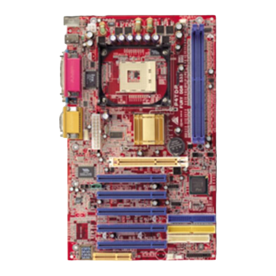
    Mic-in Phone-Buchse ist geteilt mit “Bass & Center”. Verpackungsinhalt HDD-Kable X 1, FDD-Kable X 1, Treiber-CD für Installation X 1 USB-Kable X 2 (optional) Layout des P4TDP Pro JKBMS1 JCFAN1 JKBV1 & Mouse JATXPWR2 JUSB1 JUSBV1 JCOM1 JPRNT1 JCOM2 JGAME1...
  • Seite 25: Installation Der Cpu

    Installation der CPU Ziehen Sie den Hebel seitwärts von der Sockel und neigen Sie ihn um 90-Grad nach oben. Suchen Sie Pin A im Sockel und den weißen Punkt oder die Abschnittkante in der CPU. Passen Sie Pin A mit dem weißen Punkt/der Abschnittkante zusammen und legen Sie danach die CPU ein.
  • Seite 26: Ddr-Dimm-Modules: Ddr1-2

    DDR-DIMM-Modules: DDR1-2 DRAM Zugriffszeit: 2.5V unbuffered DDR 200/266/Fuzzy333 MHz Type erfordert . (x16 hat keine Unterstützung) DRAM Typen: 64MB/ 128MB/ 256MB/ 512MB/ 1GB DIMM-Module (184 pin) DIMM-Sockel DDR-Module Speichergröße (MB) Standort DDR 1 64MB/128MB/256MB/512MB/1GB maximal ist DDR 2 64MB/128MB/256MB/512MB/1GB * Die obere Liste für DRAM-Konfiguration ist nur als Referenz gezeigt. Installation von DIMM-Modulen gibt eine...
  • Seite 27: Jumpers, Headers, Anschlüsse & Slots

    Jumpers, Headers, Anschlüsse & Slots Festplattenanschlüsse: IDE1/ IDE2 Das Mainboard hat einen 32-Bit Enhanced PCI IDE-Controller, der die Modi PIO0~4, Bus Master sowie die Ultra DMA/33/66/100 Funktion zur Verfügung stellt. Dieser ist mit zwei HDD-Anschlüssen versehen IDE1 (primär) und IDE2 (sekundär). Die IDE-Anschlüsse können eine Master- und eine Slave-Festplatte verbinden, so dass bis zu 4 Festplatten angeschlossen werden können.
  • Seite 28 Stromversorgungsanschlüsse: JATXPWR1/ JATXPWR2 JATXPWR2 (ATX 12V stromanschl.) JATXPWR1 (ATX Netzstromanschl.) Anschluss für Auswahl von DIMM Stromversorgung: JDIMMVOLT1(optional) Jumper offen ==> 2.5V Pin 1-2 geschlossen ==> 2.6V Pin 3-4 geschlossen ==> 2.7V JDIMMVOLT Pin 5-6 geschlossen ==> 2.8V (Default ==> 2.5V) Pin 7-8 geschlossen ==>...
  • Seite 29 Front USB Header: JUSB2/ JUSB3(optional) / JUSB4(optional) Pin1,2 ==> +5V Pin3,4 ==> Data(-) Pin5,6 ==> Data(+) Pin7,8 ==> GND Pin9 ==> KEY JUSB2/3/4 Pin10 ==> NA JUSB1 (auf JUSB2 JUSB3 JUSB4 Ruckwand) Kein USB 2.0-Chip 1.1-Chip 1.1-Chip Zunahme von USB 2.0-Chip 1.1-Chip 1.1-Chip...
  • Seite 30: 5Vsb Auswahl Für Usb-Wake-Up: J1(Optional)

    5V/ 5VSB Auswahl für USB-Wake-UP: J1(optional) Pin 1-2 geshlossen ==> aktiviert Pin 2-3 geschlossen ==> deaktiviert Nachdem man ein USB2.0-Chip benutzt und J1 auch in “aktiviert” Mode festgelegt wird, werden JUSB1/4(weiß) zu 5V_SB geändert. Audio Subsystem: JAUDIO1/ JCDIN1 JAUDIO1 JCDIN1 (Front Audio Header) (CD-ROM Audio-In Header) JF_AUDIO...
  • Seite 31 Jumper-Block Audio-Anschl sse f r die Vorderseite/ Jumper-Einstellen Konfiguration Pin 5 und 6 Audio-Ausgang-Singals werden zu der Audio- Pin 9 und 10 Ausgang-Anschluss an der R ckwand geleitet . Audio-Ausgang und Mic-In-Singals sind verf gbar Kein Jumper f r Audio-Anschl sse an der Vorderseite. installieren Anschlüsse auf der Vorderseite: JPANEL1 PWR_LED...
  • Seite 32: Jumper Zum Löschen Des Cmos: Jcmos1

    Jumper zum Löschen des CMOS: JCMOS1 JCMOS1 Beschreibung Normale Operation Pin 1-2 (Default) geschlosssen CMOS-Daten Pin 2-3 loschen geschlossen Anschlüsse auf der Rückwand: JKBMS1 JPRNT1 PS/2- JGAME1 Maus Gameport PS/2- COM1 COM1 COM1 Tastatur JCOM1 JCOM2 6-Kan al-Lautsprecher Speaker-Out Speaker-Out Line-In/ Mic-In Line-In/...
  • Seite 33: Warpspeeder

    WarpSpeeder Introduction [ WarpSpeeder™ ], a new powerful control utility, features three user-friendly functions including Overclock Manager, Overvoltage Manager, and Hardware Monitor. With the Overclock Manager, users can easily adjust the frequency they prefer or they can get the best CPU performance with just one click. The Overvoltage Manager, on the other hand, helps to power up CPU core voltage and Memory voltage.
  • Seite 34: System Requirement

    System Requirement OS Support: Windows 98 SE, Windows Me, Windows 2000, Windows XP DirectX: DirectX 8.1 or above. (The Windows XP operating system includes DirectX 8.1. If you use Windows XP, you do not need to install DirectX 8.1.) Installation Execute the setup execution file, and then the following dialog will pop up.
  • Seite 35 When you see the following dialog in setup procedure, it means setup is completed. If the “Launch the WarpSpeeder Tray Utility” checkbox is checked, the Tray Icon utility and [ WarpSpeeder™ ] utility will be automatically and immediately launched after you click “Finish”...
  • Seite 36: Usage

    Usage The following figures are just only for reference, the screen printed in this usr manual will change according to your motherboard on hand. [ WarpSpeeder™ ] includes 1 tray icon and 5 panels: 1. Tray Icon: Whenever the Tray Icon utility is launched, it will display a little tray icon on the right side of Windows Taskbar.
  • Seite 37 2. Main Panel If you click the tray icon, [ WarpSpeeder™ ] utility will be invoked. Please refer do the following figure; the utility’s first window you will see is Main Panel. Main Panel contains features as follows: a. Display the CPU Speed, CPU external clock, Memory clock, AGP clock, and PCI clock information.
  • Seite 38 3. Voltage Panel Click the Voltage button in Main Panel, the button will be highlighted and the Voltage Panel will slide out to up as the following figure. In this panel, you can decide to increase CPU core voltage and Memory voltage or not.
  • Seite 39 4. Overclock Panel Click the Overclock button in Main Panel, the button will be highlighted and the Overclock Panel will slide out to left as the following figure. Overclock Panel contains the these features: a. “–3MHz button”, “-1MHz button”, “+1MHz button”, and “+3MHz button”: provide user the ability to do real-time overclock adjustment.
  • Seite 40 “Verify button”: User can click this button and [ WarpSpeeder™ ] will proceed a testing for current frequency. If the testing is ok, then the current frequency will be saved into system registry. If the testing fail, system will do a fail-safe rebooting. After reboot, the [ WarpSpeeder™ ] utility will restore to the hardware default setting or load the verified best and stable frequency according to the Recovery Dialog’s setting.
  • Seite 41 5. Hardware Monitor Panel Click the Hardware Monitor button in Main Panel, the button will be highlighted and the Hardware Monitor panel will slide out to left as the following figure. In this panel, you can get the real-time status information of your system. The information will be refreshed every 1 second.
  • Seite 43 Note: Because the overclock, overvoltage, and hardware monitor features controlled several separate chipset, [ WarpSpeeder™ ] divide these features to separate panels. If one chipset is not on board, the correlative button in Main panel will be disabled, but will not interfere other panels’ functions. This property can make [ WarpSpeeder™...
  • Seite 44: Trouble Shooting

    Trouble Shooting PROBABLE SOLUTION No power to the system at all Power light don’t * Make sure power cable is securely plugged in illuminate, fan inside power supply does not turn * Replace cable on. Indicator light on keyboard does not turn on * Contact technical support PROBABLE SOLUTION...
  • Seite 45: Solución De Problemas

    Solución de Problemas CAUSA PROBABLE SOLUCIÓN No hay corriente en el sistema. La luz de * Asegúrese que el cable de transmisión esté corriente no ilumina, ventilador dentro de la seguramente enchufado. fuente de alimentación apagada. Indicador de * Reemplace el cable. luz del teclado apagado.
  • Seite 46: Problemlösung

    Problemlösung MÖGLICHE URSACHE LÖSUNG Das System hat keine Spannungsversorgung. * Versichern Sie sich, dass das Stromkabel richtig Die Stromanzeige leuchtet nicht, der Lüfter im angebracht ist Inneren Stromversorgung wird nicht * Ersetzen Sie das Stromkabel eingeschaltet. Tastaturleuchten sind nicht an. * Wenden Sie sich an Ihre Kundendienststelle MÖGLICHE URSACHE LÖSUNG...
  • Seite 47 01/28/2003...

Inhaltsverzeichnis